Virtual 3D Polygon for ADAS and Vehicle Dynamics Testing - www.dewesoft.com - Copyright 2000 - 2022 Dewesoft d.o.o., all rights reserved.
←
→
Page content transcription
If your browser does not render page correctly, please read the page content below
www.dewesoft.com - Copyright © 2000 - 2022 Dewesoft d.o.o., all rights reserved.

Virtual 3D Polygon for ADAS and Vehicle
            Dynamics Testing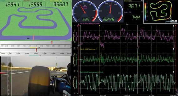
Introduction to the Polygon
Polygon is a platform for tests involving moving objects. It was made especially for vehicle dynamic testing and advanced
driver assistance systems - ADAS, which increases safety in the tra c. Polygon provides a visual representation of
measurements in the three-dimensional virtual space. It also provides easy tools for geometric measurements between
multiple static or movable objects. Polygon visualization and outputs can be calculated during the measurements or after in
offline mode. Due to its flexibility it's not only used in Automotive, but also Marine, Heavy machinery, ...

[Video available in the online version]

[Video available in the online version]

                                                                                                                          1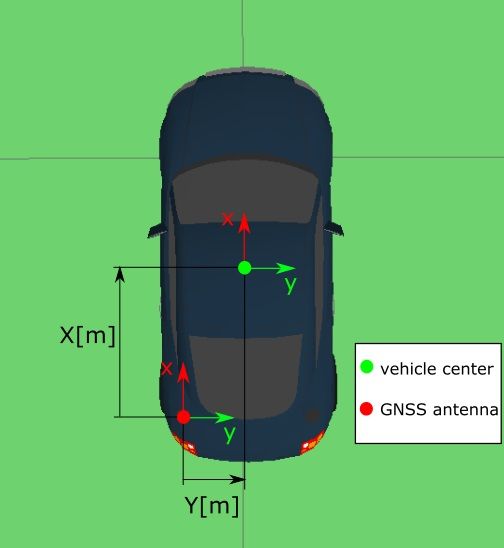
How to install the Polygon plugin?
Polygon works as a Dewesoft X plugin. To install it, please copy Polygon.dll to the Addons folder of Dewesoft X Software.
Then open the Dewesoft X software, go to Settings -> Extensions and click on the plus button. This will open an extension
manager. The Polygon plugin should appear in the extension manager list, where you have to enable it to make it work. If the
plugin is successfully enabled it will appear in the extension list. If you don't find the plugin in the extension manager click to
refresh the list in the extension settings.

                                                                                                                                      2
Optional plugin: Vehicle Simulation
If you want to test Polygon setups before use or want to learn how to use the Polygon plugin o ine there is an additional
Vehicle Simulation plugin available - VehicleSimulation.dll library. The installation process is the same as with the Polygon
plugin. Vehicle simulation plugin automatically adds longitude, latitude, and heading channels that can be used to move
vehicles in the Polygon environment. The added channels can be controlled with keyboard arrows or with joystick movement.
34
How to setup the Polygon?
Under channel setup click on the Polygon button in the main toolbar. Polygon setup contains four sections:

              On the left top is the object list with all of the objects (vehicles, cones, gates, lines) needed for measurement
              and their basic properties like name, color, show/hide option.
              Under that is the object property section with detailed properties for selected object. Some properties like
              moving characteristics are similar for all objects and others are object type dependent, like dimensions for
              vehicle, position for cones, width for lines and routes.
              On the bottom left is the output list, where all the polygon outputs like distances, angles, gate cross triggers can
              be defined. Outputs automatically become new data channels.
              On the right side of the display there is a polygon 3D preview with view angle settings.

To see the polygon on the measure screen just put Polygon3D component on it and connect it to the Polygon visual group. If
there is just one visual group suitable for Polygon3D visual component then it will be automatically assigned.

                                                                                                                                 5
Which Objects can be used?
Polygon offers six different types of objects. Each of them has specific properties, behavior, and calculation options:
Vehicle,
Simple object,
Line,
Route,
Circle,
Travel radius.
Settings which de ne how object moves are common for all objects. It's normal for a vehicle to move and for a route to be
xed, but there can be exceptions so any object can be xed or moving. There are actually three options. Object can be
Moving, Fixed, or defined as Moving with:
Fixed object is xed to the ground and X and Y are relative positions regarding the origin (they represent the
coordinates in the fixed coordinate system).
Moving objects needs Latitude, Longitude, and Heading channels to be assigned to them. In this case X and Y
coordinates de ne shift from the Latitude, Longitude, and Heading value (they represent coordinates in the
moving coordinate system).
Third option 'Moving with' is similar to Moving, but here some other moving object is set as the reference
instead of Latitude, Longitude and Heading channel.
There is also an option Freeze on trigger, which can be de ned for the 'Moving' or 'Moving with' type of objects. When the
value of a trigger channel reaches the speci ed condition the object will stay on its place and further changes of Latitude,
Longitude, and Heading from the master object won't change its position. If an object moves with another object it will also
freeze when the master object freezes.
67
Objects: Vehicle, Simple object and Line
In the following section objects Vehicle, Simple object, and Line will be described.

Vehicle
The vehicle is usually the       rst object we need. It's normally a moving object, with Latitude, Longitude, and Heading
channels from GPS, DS-IMU, ADMA, or some other device. Length and Width should also be de ned if we want to calculate
distances from the edges of the vehicle. There are also X and Y coordinates which represent the shift of the vehicle center
from the point given by Latitude and Longitude (usually GPS antenna position). If the antenna is at the back then X should be
positive (vehicle shifted forward), if it is on the left Y should be positive (vehicle shifted right).

                                                                                                                            8
Settings for vehicle size can be moved out of the setup and out of the setup le. This can be used in cases when the same
setup is used with different vehicles or when those settings should be set in the Data header (on start when Sequencer opens
it for example). If there is entry with Unique ID VehicleLength and VehicleWidth in Data header then it will be xed to those
two values and disabled in setup (will be still shown, but disabled).
Simple object
A simple object is a single point in the polygon, visually represented with a tra c cone. It's normally a xed object, but can
also be moving. If it is xed then X and Y determine the position on the xed coordinate system, if it is moving then X and Y
determine its position in the moving coordinate system. So the Simple object can be cone in Lane change test, microphone in
Pass-by noise test, but it can also represent any custom interest point inside or outside of the vehicle (or other moving
objects), which we can use to calculate distances to.
9Line
Line is de ned with two points. It's also normally xed object, but can also be moving. The order of points is important, line
direction is de ned as a direction from rst to the second point. Depending on the side on which the measured object lays the
calculated distance is either positive or negative. If it is on the right then distance will be positive and if it is on the left then it
will be negative.
The width is also important. Not just for visualization, but also for distance calculation if the distance from the edge is
calculated. Line can for example represent the straight lane in Lane departure test or Lane change test, but it also has one
additional function. It can also act as a crossing trigger (more about that in the output section).
10Objects: Route, Circle and Travel radius
In the following section the other three objects will be described: the [Video available in the online version]
11How to determine the Coordinate Systems and Origin?
Coordinate Systems
[Video available in the online version]
SETUP WITH TWO POINTS
GNSS position from one movable antenna is needed,
data has to be connected to a vehicle type object in
the polygon environment. For the origin de nition two
reference points on the test area have to be chosen.
Reference points should be as far apart as it is
feasible on the test site. This reference points have to
be added on the modeled test track in polygon as
simple objects (you can also choose existing cones as
reference points). Vehicle object with GNSS data
connected to it has to be chosen as the object with
which the origin is going to be set. To set point 1 we
move the GNSS antenna on the position of the rst
reference point on our test area and press the button
'Set point 1'. The same has to be done to set up the
point 2.
[Video available in the online version]
ORIGIN SETUP WITH IMPORTED ROUTE
Origin can also be set with a route imported in the
polygon environment. If prior to import origin hasn't
been set the route import will automatically set it. The
12origin zero point is going to be located in the route
start point with the origin direction (X-axis of the xed
coordinate system) pointed in the route start
direction. Origin position can always be reset and
redefined.
13What the Accurate Origin is important for? 14
What the Accurate Origin is important for?
Origin has to be de ned accurately to ensure that
objects positions in the polygon environment
correspond to the position on the real-world test track.
Two mistakes can be made during origin setup: wrong
de nition of origin zero point or wrong de nition of origin
orientation.
Wrong de nition of origin zero point can happen when
we position the GNSS antenna is in the wrong position
on the test track that doesn't match the position of our
modeled environment. Errors from this mistake are
constant throughout the test area (constant offsets
between objects on the real test site and objects
modeled in polygon). These errors can be noticed with
a comparison of the GNSS antenna position on the real
test track compared to the position of it (object
connected to it) in the polygon environment.
Error in origin orientation is made when GNSS heading
isn't aligned with the X-axis orientation of the real test
site (origin set up with current position and heading), or
with positioning error in the two-point de nition.
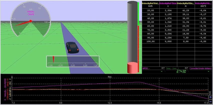
Positional errors increase with the distance from the
origin, small errors in orientation de nition can produce
large positional errors away from the origin. Therefore
it is recommended to use a two-point origin de nition
when positional accuracy of the test area is needed
(examples: slalom, lane change, pass-by noise).
15Heading angle Distance X
error 100 m 200 m 300 m 500 m 800 m 1000 m
0,1° 0,17 0,34 0,51 0,85 1,36 1,70
0,2° 0,35 0,70 1,05 1,75 2,80 3,50
0,5° 0,87 1,74 2,61 4,35 6,96 8,70
1° 1,75 3,50 5,25 8,75 14,00 17,50
16Which Outputs Channel can be created?
Polygon outputs are de ned in the output table each
speci ed output becomes a new data channel in the
measurement.
[Video available in the online version]
17Which Output Types can be defined?
There are seven types of outputs (distance, distance X,
distance Y, angle, and gate cross trigger). Each has its
own add button in the output table.
Distance gives a distance between two objects.
They can both be moving or one can be xed. All
types of objects are supported for distance
calculation, but there are few rules which were
already explained about which object should be
first, meaning of positive negative result and so on.
X and Y distance calculate longitudinal and lateral
distance looking from the first object. They can be
calculated between vehicles and simple objects
(fixed or moving). If X and Y position of some
object on the fixed coordinate system is required
then first put a simple object in the center (fixed
object at position x=0, y=0) and then calculate X
and Y distance from that center object to the
moving object.
Angle calculates the heading deviation between
two objects. It can be calculated between two
vehicles or Line, Route, Circle or Travel radius, and
18Vehicle (vehicle should always be the second
object). Like already mentioned in general
clockwise is positive, but with circular objects
heading vector pointing outwards is positive and
inwards is negative.
Gate cross trigger changes its value from zero to
one and back to zero again when moving object
crosses the line. The first object must always be a
line (representing the gate) and the second object
must be a vehicle or a simple object (custom
interest point).
Time outputs relative time from the previous time
reset in seconds and resets the timer. One of the
objects in the measurement has to be a line.
Output is changed when the other specified object
(vehicle, simple object) crosses the line center. One
line with time setting can be used to record lap
times on a looped track.
Time reset resets the relative timer and outputs
the absolute time from the start of measurement
in seconds. One of the objects in the measurement
has to be a line. Output is changed when the other
specified object (vehicle, simple object) crosses
the line center. Normally this setting is used on
start lines of non-looped tracks (acceleration runs,
brake tests).
Radius outputs the specified travel radius value in
meters. It uses only the specified travel radius for
the object of measurement. It can be set to output
either radius or inverse radius. An inverse radius is
used when we want to avoid the large values of the
radius when the moving object path comes close
to a straight line.
1920
How to 3D Visualize everything?

Visual settings are the same in setup and measure
module but they don't in uence each other.
Visualization settings do not influence the measurement.

Camera position

Manual means that the view angle can be adjusted to
any position manually. It can be translated with the
right mouse button, rotated with the left mouse button
and zoomed in and out with the mouse wheel or
pressing both mouse buttons and moving the mouse up
and down.

Attach to car view can also be set with the mouse
(move, rotate, zoom). Similar to manual but with one
big difference that camera will move with the vehicle
(first vehicle on the list if there are more than one). The
camera will move with the vehicle but will not rotate
with it.

Follow car view can also be set with the mouse (move
up and down and zoom). In this case the view will follow
the car and also rotate with the car. By default the
camera will be at the back of the car following it like in
driving simulation games. It's suitable for driving
assistance when following virtual routes.

Vehicle presentation

                                                          21
Vehicle can be visualized with a 3D model ( Vehicle) or
as an exact size rectangle on the ground (Exact sized
box).
22Example I: Brake test
Polygon can be used to measure lateral and heading
deviations on braking . Braking lane has to be de ned
(polygon line or route). If tests are repeated on the
same test lane braking lane should be xed. If we are
testing in an open area without the real brake lane
de ned we can choose a moving brake lane that is set
up to freezes on trigger (brake pedal actuation,
threshold deceleration). For brake tests in a curve a
travel radius which freezes on the trigger can be used.
23Brake test polygon setup consists of two objects,
vehicle and it's travel radius. The travel radius is set to
freeze on the trigger. Event count of brake test math is
used for lane freeze. When the brake test starts its
Event count goes to 2, travel radius freezes. Two
polygon outputs calculate lateral deviation (distance
from lane center to vehicle center) and heading
deviation (angle between lane direction and vehicle
heading).
24Example II: Lane departure
[Video available in the online version]Lane Departure
Test Data File Recording
25Example III: Lane change
Lane change test consists of three lanes: enter, leave,
and shifted lane. They can be represented with lines
precisely positioned in the polygon. In reality cones
would be placed on the test surface to mark lanes, but
they do not need to be implemented in polygon. Lane
edges can do their job.
For average speed calculation we also need start and
nish gate. In polygon terminology this would be two
lines and two Gate Cross outputs, which can then be
used as start and stop trigger in statistics to calculate
average speed. The calculation can also be triggered
with car X and Y position.
[Video available in the online version]
[Video available in the online version]
26Example IV: Functional Safety
There are many types of functional safety (FuSi) tests.
Straight line and steady-state cornering tests are
simpler, but there are also tests with more complex
prede ned maneuvers like the Dog-track test. For
straight line and steady-state cornering tests we just
need a vehicle and its travel radius. Travel radius will
represent the predicted vehicle path in normal
conditions (without error injected). Due to the steady
nature of simpler tests the predicted path from the
travel radius is going to be fairly accurate. At the
moment when an error is injected in the car electronic
control system the predicted vehicle path (travel radius)
is frozen. Vehicle lateral and angle deviations are then
calculated using the frozen travel radius as a reference.
If a prede ned maneuver has to be driven before the
error is injected the route of the maneuver can be
prede ned (manual route creation, route recording, and
import). Route can be either positioned xed on the
polygon (in setup) or moving with a vehicle with a
freeze on trigger function. Freeze can be triggered with
a button, speed threshold The polygon view can from
then on be used as driver assistance. From here on the
procedures and analysis is the same as with the simpler
tests.
2728
Example V: IIHS Headlight Testing

[Video available in the online version]

                                          29
You can also read