Under consideration to be published in OMAE 2022
←
→
Page content transcription
If your browser does not render page correctly, please read the page content below
Proceedings of the ASME 2022 41th International
                                                                                                                       Conferences on Ocean, Offshore and Arctic Engineering
                                                                                                                                                                  OMAE2022
                                                                                                                                         June 5-10, 2022, Hamburg, Germany

                                                                              Under consideration to be published in OMAE 2022
arXiv:2201.03352v1 [physics.flu-dyn] 10 Jan 2022

                                                                   DRAFT: PROPULSIVE PERFORMANCE OF MORPHING AND HEAVING FOIL

                                                                                    Ishan Neogi, Vardhan Niral Shah, Pragalbh Dev Singh, Vaibhav Joshi∗
                                                                                                    Department of Mechanical Engineering
                                                                                                 Birla Institute of Technology & Science Pilani
                                                                                                              K K Birla Goa Campus
                                                                                                                Goa, India 403726
                                                                                                     Email: vaibhavj@goa.bits-pilani.ac.in

                                               ABSTRACT                                                                     engineering designs in bio-mimetics and give insights on design
                                                    Biological locomotion, observed in the flexible wings of                conditions for optimal thrust performance.
                                               birds and insects, bodies and fins of aquatic mammals and fishes,
                                               consists of their ability to morph the wings/fins. The morphing
                                               capability holds significance in the abilities of fishes to swim up-         INTRODUCTION
                                               stream without spending too much energy and that of birds to                      Flexible flapping of wings or foil-defined structures like fins
                                               glide for extended periods of time. Simplifying the wing or fins             is a mechanism of lift and thrust generation commonly found
                                               to a foil, morphing refers to the ability of the foil to change its          in avian and aquatic life. Birds and fishes flap their wings
                                               camber smoothly, without sharp bends on the foil surface. This               and fins to propel themselves into the air or through the water.
                                               allows precise control over flow separation and vortex shedding.             Thus, inheritance of the evolutionary designs present in biolog-
                                               Compared to conventional trailing-edge extensions or flaps, used             ical sources can prove to be advantageous and more efficient
                                               in rudders and elevators in submarines and ships, morphing foils             in optimizing the lift and thrust generation [1, 2, 3]. Such bio-
                                               provide better control of thrust and lift characteristics. This study        inspired designs, like ornithopters, have attracted significant at-
                                               aims at understanding the importance of the morphing of foil                 tention due to their non-reliance on traditional propulsion mech-
                                               combined with a sinusoidal heaving motion on thrust generation.              anisms like propellers and jets, the resemblance to wildlife, their
                                               A two-dimensional variational stabilized Petrov-Galerkin mov-                efficiency in some regimes [4] and their potential in micro-to-
                                               ing mesh framework is utilized for modelling the incompressible              nano scale robotics. A key feature of biologically-inspired de-
                                               low Reynolds number flow across the flapping foil. The morph-                signs is the flexibility of structures, and this is yet another feature
                                               ing motion is characterized by the extent of morphing, measured              that has gained significant attention recently with the advent of
                                               as an angle of deviation from the initial camber, and the point              soft robots and compliant mechanisms, recently implemented in
                                               of initiation of morphing on the foil as a percentage of its chord           aircraft wing extensions [5, 6].
                                               length. The effect of the foil morphing and the heaving motion
                                                                                                                                 A simplification of the motion of wings and fins may be
                                               on the propulsive performance are investigated. The extent of
                                                                                                                            ascribed to a combination of three independent motions, mor-
                                               morphing is varied from -30◦ and 30◦ , and the point of initia-
                                                                                                                            phing, heaving, and pitching. The combination of heaving and
                                               tion ranges from 15% to 50% of the chord. The Reynolds and
                                                                                                                            pitching has been extensively studied, both numerically and ex-
                                               Strouhal numbers for the study are 1100 and 0.2, respectively.
                                                                                                                            perimentally, and in isolation, flexible foils have been studied as
                                               The results from the current work can pave the way for enhanced
                                                                                                                            an analogue for morphing. Biologically inspired unmanned un-
                                                                                                                            derwater vehicles have experimented with flapping motion as a
                                                   ∗ Address   all correspondence to this author.                       1                                         Copyright © 2022 by ASME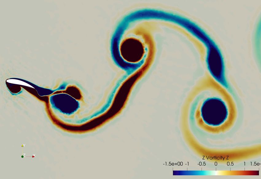
source for thrust, however, the current applications are limited            mechanisms. The first is the ability of fish to only morph a cer-
to rigid foils where the flapping motion is approximated by only            tain section of their body. A fish may only flap its caudal fin or
compounding heaving and pitching motions [7, 8, 9]. Extensive               may morph its whole body to move. The second control mecha-
studies have been performed to understand the flow and effect               nism is the ability to control the amount of deflection. This study
of various parameters like chord ratio, phase difference, and gap           focuses on the effect of the morph position (i.e. the location of
ratio for this approximation of a single foil [10] and tandem con-          the onset of morphing along the foil chord) and the morph ampli-
figuration [11, 12, 13, 14, 15, 16, 17, 18, 19, 20, 21, 22].                tude (deflection of the trailing edge from mean position) on the
      While rigid foils are pragmatically sound with respect to             propulsive performance of a foil that is heaving and morphing.
manufacturing and structural constraints, wings and fins in na-             We extend the study performed in [22] by replacing and compar-
ture are almost always highly flexible, and the chord-wise de-              ing the pitching motion by morphing. This can be justified since
formation of the foil adds to the efficiency and performance of             pitching causes a periodic change in angle of attack which is also
propulsion. The change in the camber of the foils (hereby re-               observed in morphing along with camber variation. We expect a
ferred to as morphing of foils) can allow for precise control over          similar flow pattern. We restrict ourselves to a single foil here for
lift and drag characteristics, thus altering flow structures and en-        a clear comparison in flow induced by pitching and heaving.
hancing thrust performance and/or efficiency. Uncontrolled flex-                 A symmetrical NACA 0015 foil is considered at the
ibility (two-way coupling between foil and free stream flow)                Reynolds number Re = 1100. The foil heaves with an amplitude
has shown to have some benefits in thrust performance within                of one chord length. The phase difference between heaving and
restrictive regimes [23], but is without any heaving or pitch-              morphing is taken to be π/2 ahead in favor of heaving, meaning
ing. Other studies that focus on morphing, including the pre-               the morph of the foil will be greatest when the foil is at its cen-
vious one mentioned, focus on the performance of morphing in                tral heave position. The onset of morphing varies between 0%
high Reynolds flow which is characterized by the formation of               and 50% of the chord length, and the morph amplitude ranges
Kelvin–Helmholtz vortices [24,25,26,27,28,29,30,31,32,33,34].               between 10◦ and 60◦ . The numerical framework solves the in-
Results obtained in these studies support the use of morphing for           compressible Navier-Stokes equations in two-dimensions, dis-
a favourable CL /CD ratio. Although these results don’t apply               cretized by variational stabilized Petrov-Galerikan finite element
to our low Reynolds number set-up, they provide motivation to               formulation in a moving-mesh Arbitrary Lagrangian-Eulerian
study the behaviour of morphing in the current setup.                       (ALE) framework.
      In order to truly understand and mimic the thrust generation               The outline of the article is as follows. The numerical frame-
capabilities of birds and fishes, it is necessary to combine these          work of the study is discussed first, where the flow modelling
individual elements together in one study. Moreover, there is ne-           equations and discretization, mesh characteristics and the mech-
cessity to conduct studies in low Reynolds number flows as a                anism of morphing are laid out in detail. Key results and trends
large number of applications correspond to this regime. Seldom              are presented thereafter, with emphasis on the difference between
are there reliable studies that combine morphing with heaving               pitching and morphing, and the individual impacts of morph am-
or pitching or both, and none that utilize a prescribed camber              plitude and position. The study is then concluded with key find-
morph, as per the knowledge of the authors. This study will                 ings and opportunities for future work are highlighted.
analyse the thrust performance of a morphing and heaving foil
at low Reynolds number regime, and will compare a variety of
camber-specific morphing states to understand the effects of key
                                                                            NUMERICAL FRAMEWORK
geometric factors while morphing.
                                                                                 In this section, we describe the numerical framework uti-
      The muscles within the wings of birds and bodies of fish al-
                                                                            lized for simulating the combined heaving and morphing of foil.
low them to bend their bodies in precise ways, and the intention
                                                                            The prescribed motion on the foil is described along with the
of this study is to mimic that pre-determined control of morph-
                                                                            flow modeling in the moving mesh framework.
ing. If the flexibility and deformation of the foil is controlled and
prescribed along side heaving and/or pitching, benefits of both
worlds can be gained and the performance characteristics of the             Prescribed Motion of the Structure
mechanism may be tuned to any application. The applications                      The structure (a foil in the present case) is prescribed a heav-
of such a fully controllable variable camber foil (i.e., morphing           ing and morphing motion, both of which are varying sinusoidally
foil) are immense, and find uses in the development of micro air            with time. The heave position is given by h(t) and the amount
vehicles, AUVs, nano-robotics in a myriad of fields and energy              of trailing edge deflection (i.e. morph amount) is denoted by the
harvesting systems.                                                         variable θ .
      The geometric comparison of the morphing of the foil will
be mimicing two control mechanisms present in aquatic and
avian life. Let us take the example of fish to understand these                                  h(t) = h0 sin(2π f t + φh )                 (1)

                                                                        2                                        Copyright © 2022 by ASME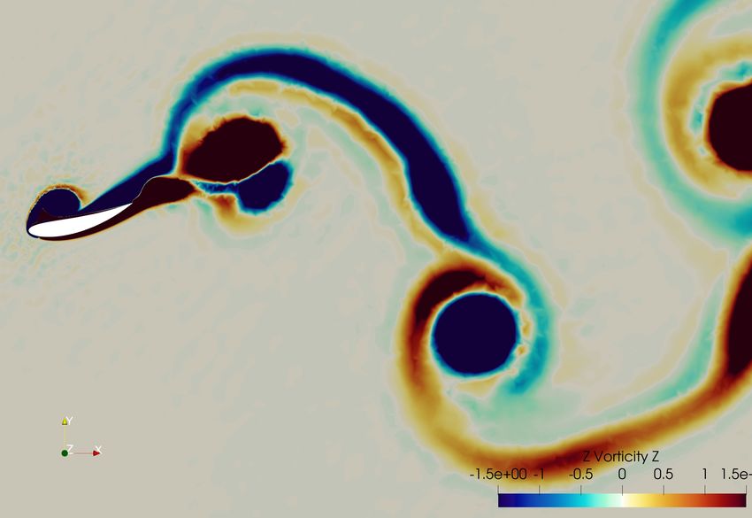
1             2          3

                                                                                         Start Point 1

                              θ1
                                             θ2

                     1             2
                                              3
                                                                                                  Start Point 2

            FIGURE 1: MORPHING MECHANISM
                                                                                        Fixed Part                      Morphing Part

                         θ (t) = θ0 sin(2π f t)                   (2)        FIGURE 2: VISUALIZATION OF THE START POINT LOCA-
                                                                             TION FOR MORPHING
     where h0 and θ0 are the amplitudes of heaving and morph-
ing respectively, f denotes the frequency of motion and φh is the
phase difference between morphing and heaving. The study pa-
rameters are starting position of morphing, x0 , the point aft of
which the foil will morph, i.e., there will be no camber change in
the section of foil between the leading edge and the cx0 , c being
the chord length of the foil.                                                                          α
     The mechanics of morphing is designed in such a way that a                          y
smooth surface of the morphed foil can be obtained. In order to
meet this goal, the morphing of the foil has been approximated as                                  x
the rotation of several minute rigid body sections, as represented
                                                                             FIGURE 3: ANGLE OF ATTACK AND COORDINATE SYS-
in Fig. 1. The required morphable part of the foil is divided into
100 sections. The number chosen here is arbitrary, the smooth-               TEM
ness of the foil is well defined at 100 and any larger number will
not significantly increase the smoothness of the surface. Each
                                                                             number, fluid properties and geometry of foil) and:
section is then rotated by an angle of θ /100 about the central
point in the foil, relative to the section just preceding it to obtain
the net morph state. In Fig. 1, the foil is divided into 3 sections,                         VY = −(h(t))0 = −2πh0 f cos(2π f t + φh ).                    (3)
the latter two of which rotate by an angle of θ1 and θ2 respec-
tively, thus giving total morph angle = θ1 + θ2 . For this case, θ1
= θ2 = Total Morph angle / 2. The green circles represent the                The angle of attack is taken as positive in the counter-clockwise
points of rotation, each section rotates about the green circle just         direction, as shown in Fig. 3.
preceding it.
     The visualization of the starting morphing location is de-              Flow Modeling
picted in Fig. 2. The effective angle of attack (AoA) of the foil                 For this particular flow model, a two-dimensional incom-
as it moves will be an important factor to explain certain per-              pressible Navier-Stokes equation and a moving mesh framework
formance characteristics, and it is dependent on the velocity of             called arbitrary Lagrangian-Eulerian (ALE) are used. The mo-
the free stream flow, the position of the foil while heaving and             mentum and the continuity equations are given as:
morph amount and position. The velocity of the free stream flow
is defined to be relative to the foil motion, and can be broken
down into two mutually perpendicular components in X and Y                            ∂ vf
                                                                                 ρf              + ρ f (vvf − w ) · ∇vvf = ∇ · σ f + ρ f b f , on Ωf (t)   (4)
axes, given by VX (a constant component depending on Reynolds                         ∂t     χ

                                                                         3                                                 Copyright © 2022 by ASME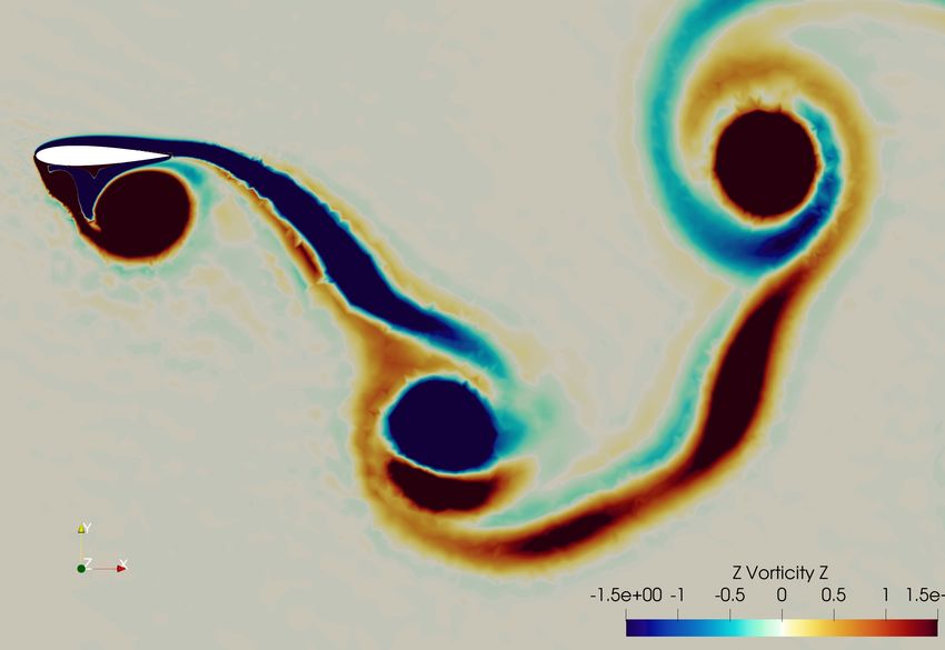
∇ · vf = 0                          (5)

Here, w is the mesh velocity, v f is the fluid velocity with vfx , and
vfy its two components in x and y directions, respectively. The
Cauchy stress tensor σ f for a Newtonian fluid is given as:

                  σ f = −pII + µ f (∇vvf + (∇vvf )T ),            (6)

where µ f is the dynamic viscosity of the fluid, p is the fluid pres-
sure, and I is the identity matrix. The body force and fluid den-
sity are represented by b f and ρ f respectively. χ denotes the ALE          FIGURE 4: THE COMPUTATIONAL MESH FOR THE FOIL
referential coordinates in Eq. (4).                                          ALONG WITH THE REFINED BOUNDARY LAYER MESH
     Temporal discretization for the governing equations is car-
ried out using the Generalized-α method ( [35]), and finite el-
ement variational stabilized method is employed for the spatial              RESULTS AND DISCUSSION
discretization. The variational formulation for the flow equation                 In this section, we analyse the effects of the morphing on
can be found in [22, 36].                                                    the lift and thrust of the foil, and try to explain the trends us-
                                                                             ing vorticity plots. We aim to computationally study the effects
                                                                             of morphing position and amplitude on the propulsive perfor-
Fluid Structure Interface                                                    mance of the foil. For all the cases, the heave amplitude h0 /c = 1,
     The fluid-structure interaction is one-way in the current sce-           f c/U∞ = 0.2, Re = ρ fU∞ c/µ f = 1100 and φh = π/2, where U∞
nario, as the structural displacements are known a-priori. By                is the free stream velocity.
equating the fluid and structure velocities, the kinematic conti-
nuity condition is satisfied at the fluid-structure interface as
                                                                             Effective Angle of Attack
                                                                                  The effective angle of attack of the foil is a key parameter to
               v f (ϕ  X ,t),t) = v s (X
                    ϕ (X               X ,t), ∀ X ∈ Γfs .         (7)        understand the nature of lift profile of the regime. The effective
                                                                             angle of attack, given by αe , is a product of the angle of attack of
                                                                             the foil in horizontal free stream flow, α, the horizontal velocity
     Here, ϕ is a bijection from the structural initial position X at        of the free stream flow VX and the oscillating vertical component
                                      X ,t) = X + u s (X
t = 0 to an arbitrary time t, i.e. ϕ (X                X ,t) where Γfs       of velocity due to heaving, VY .
                                          s
denotes fluid structure interface and u is the structural displace-               The angle α is estimated using the coordinates of the leading
ment.                                                                        and trailing edge of the foil over time as it is morphing, VX = 1î
     The verification of the formulation along with mesh con-                and VY is given by Eq. 3. Figure 5(a) shows the variation of
vergence and validation has been carried out in the previous                 αe over morph amplitudes and time for a representative morph
works [21,22] and will not be dealt with in the current work. The            position of 0.3c and Fig. 5(b) depicts the same variation over
mesh convergence study performed is applicable for the mesh                  morph positions and time for a representative morph amplitude
utilized for the current study. This ensures that the mesh is re-            of 30◦ . All other plots for αe follow a similar trend.
fined enough for the study. A representative close-up view of the
mesh is shown in Fig. 4.
                                                                             Thrust, Lift and Power Coefficients
                                                                                  The effect of the morph amplitude on the mean thrust coef-
Parameters of Interest                                                       ficient CT,mean and maximum thrust coefficient CT,max is shown
     The parameters of interest for this study are the same as               in Figs. 6(a) and (b), respectively. When the onset of morphing
in [21, 22]. To reiterate, the parameters of interest are the coeffi-        is closer to the leading edge (i.e., morph position = 0%, 10%,
cient of thrust (CT ), coefficient of lift (CL ), coefficient of power       20%), CT,mean increases with the morph amplitude till a maxi-
(CP ) and propulsive efficiency η. All variables are calculated              mum value is reached (approximately at amplitude = 40◦ ), fol-
in the same way as stated in [21, 22]. Further analyses are per-             lowed by a decreasing trend. This variation gradually reverses
formed to explain trends and observations in the behaviour of                as the onset of morphing tends towards the trailing edge till an
these parameters using pressure and vorticity maps over several              overall decreasing trend is observed at morph position of 50%.
cycles of the prescribed motion.                                             For a fixed morph amplitude, shifting the onset position to the

                                                                         4                                        Copyright © 2022 by ASME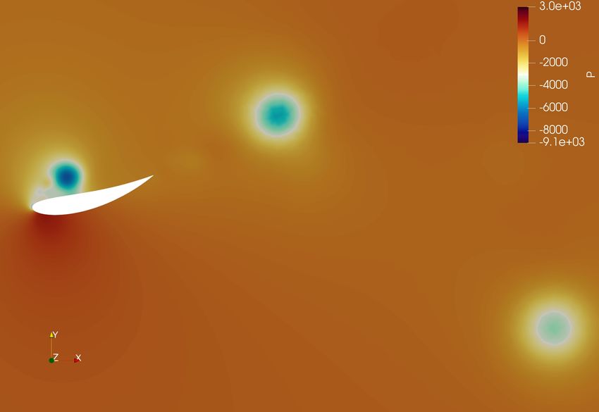
(a)
                                                                                                         (a)

                               (b)

FIGURE 5: VARIATION OF αe IN A FLAPPING CYCLE FOR
A CONSTANT (a) MORPH POSITION OF 30%, AND (b)                                                            (b)
MORPH AMPLITUDE OF 30◦
                                                                         FIGURE 6: VARIATION IN THE THRUST COEFFICIENTS
                                                                         WITH MORPH AMPLITUDE: (a) CT,mean , AND (b) CT,max
trailing edge seems to have an adverse impact on thrust-favoring
conditions as CT,mean decreases. Periodic variation of CT in a cy-
cle is shown in Fig. 7 for a representative morph position of 0%.        t/T = 0.25.
A delay is observed in the peak of the thrust coefficient as morph            The variation in the lift coefficient is shown in Figs. 8 and
amplitude increases.                                                     9. CL,max decreases monotonically with increase in morph am-
      The maximum thrust coefficient CT,max depicted in Fig. 6(b)        plitude, however CL,mean does not follow a generic trend. The
shows an overall similar variation as CT,mean , with some differ-        effective angle of attack of the foil, shown in Fig. 5 can shed
ences. CT,max is observed in the range t/T = (0.2,0.3) for all po-       some light on the cause of the variation in lift coefficient. Lower
sitions and amplitudes. This is supported by the fact that the           positions (example, Position = 0% and 10% in Fig. 8(a)) do not
maximum projected area (at maximum morphed state) occurs at              reach high enough effective angle of attack (Fig. 5(b)), explain-

                                                                     5                                         Copyright © 2022 by ASME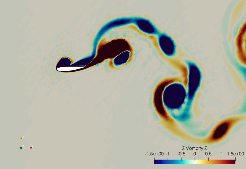
FIGURE 7: VARIATION IN THE THRUST COEFFICIENT CT
WITH TIME FOR MORPH POSITION OF 0% (a)
ing lower morph positions have a lower CL,mean (Fig. 8(a)). Posi-
tion 20% onwards, the combined effects of increasing αe by in-
creasing morph position and decreasing αe by increasing morph
amplitude are evident. Since the increase of morph amplitude
and position cause opposite effects, there is a drastic change in
behavior of plots of higher morph positions. The variation in
CL,max is monotonically decreasing as the maximum αe attained
reduces with increase in morph amplitude for any morph position
(Fig. 5(a)).
The variation of the power coefficient, CP,max and CP,mean
is given in Fig. 10 where a decrease in the coefficient with the
morph amplitude is observed. Propulsive efficiency η is shown
in Fig. 11 which increases with amplitude as CP,mean decreases
and CT,mean increases in most cases.
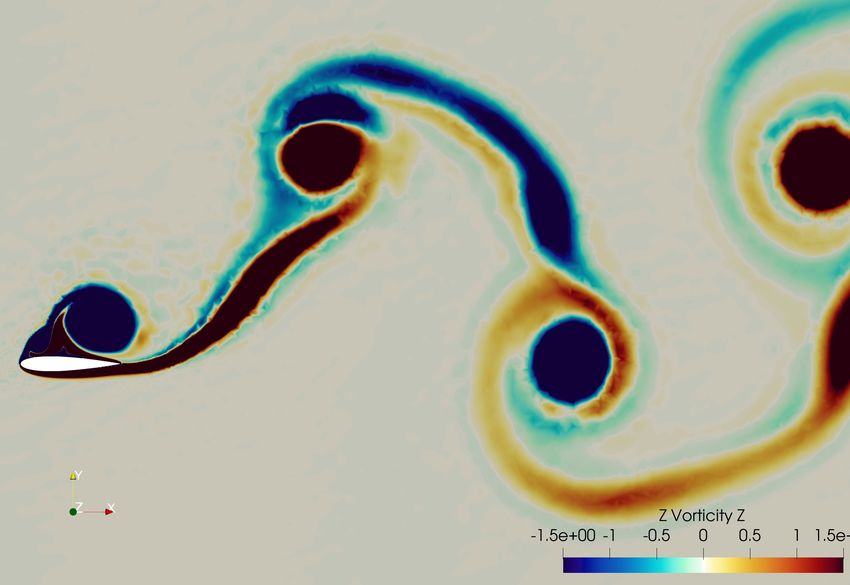
Flow Visualization
In the following sections, the development of the wake sig- (b)
nature throughout a time period has been analysed for a single
foil to understand the effect of morph amplitude and position on FIGURE 8: VARIATION OF LIFT COEFFICIENT (a) CL,mean
the foil performance. and (b) CL,max WITH THE MORPH AMPLITUDE AND POSI-
The wake of the morphing foil is visualized with the help TION
of contours of Z-vorticity in Fig. 12 for the case with morph
position of 0% and amplitude of 30◦ , along with the pressure
contours. The parameters of study have been selected such that vortices, leading edge vortex (LEV) (circular) and trailing edge
the morphing foil falls in the propulsive regime, indicated by the vortex (TEV) (elongated) are formed during upstroke and down-
inverse von-Kárman vortex street, which leads to thrust genera- stroke. LEV plays a major role in thrust generation by creating
tion. a suction region on the upper surface of the foil during down-
The motion of the foil consists of a downstroke (referred stroke and on the lower surface during upstroke, as was discussed
from here on as ds) (Fig. 12(a) to 12(c)) followed by an up- in [22]. During downstroke, LEVs generated are clockwise and
stroke (us) from Fig. 12(c) to 12(a) of next cycle). Two kinds of negative (blue in color) on the upper surface of the foil (Fig.
6 Copyright © 2022 by ASME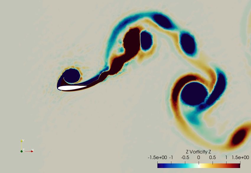
(a)
FIGURE 9: VARIATION OF LIFT COEFFICIENT CL WITH
TIME AND MORPH AMPLITUDE FOR MORPH POSITION
OF 0%

12(c)).
    The vorticity and pressure contours of all the cases will be
analysed to give an insight on the effect of morph position and
amplitude on the thrust generation by the foil. We make an at-
tempt to give some insight on the following questions:
 1. How is morphing different from the previously studied flap-
    ping (combined pitching and heaving motion)?
 2. How does the amplitude of morphing affect thrust perfor-
    mance?
 3. How does the position of morphing affect thrust perfor-
    mance?

Comparison Between Morphing and Flapping Foils
     As can be observed from Fig. 12(a) at t/T = 0, the leading                                           (b)
edge vortex from the upstroke of the previous cycle [LEV-us(n -
1)] has fully developed on the lower surface of the morphing foil          FIGURE 10: VARIATION OF POWER COEFFICIENT (a)
(referred here as foil-2 for the combined morphing and heaving             CP,mean and (b) CP,max , WITH THE MORPH AMPLITUDE AND
motion). Compared with the flapping (combined pitching and                 POSITION
heaving) motion in [22] (referred here as foil-1) where the foil
was given a pitching motion of amplitude 30◦ , there are subtle
differences in the flow patterns albeit the fact that both the cases       exist, pressure differential across the foil and the shear forces
produce thrust-generating inverse von-Kárman vortex street.               acting on the surface.
     It is observed that for a particular amplitude when the en-                Observation 1: The amount of projected area in the stream-
tire foil is morphed, i.e., morph position is 0%, CT,mean is less          wise direction gives the insight about the difference in mean
than that of the flapping foil with similar amplitude of pitching          thrust coefficients of pitching and morphing foils. A larger area
motion. The thrust coefficient CT,mean depends on the projected            along with favorable conditions (high pressure on lower surface
area, duration for which favorable thrust-generating conditions            and low pressure or suction on upper surface of the foil during

                                                                       7                                        Copyright © 2022 by ASME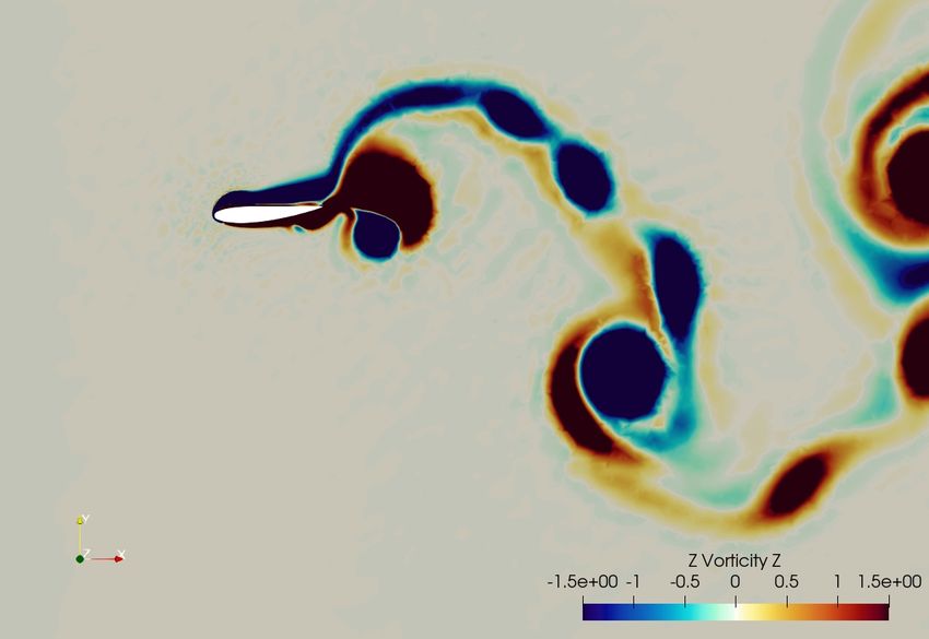
(a) t/T = 0

                                                                                                       (b) t/T = 0.25

FIGURE 11: VARIATION OF PROPULSIVE EFFICIENCY η
WITH MORPH AMPLITUDE AND POSITION

downstroke and vice-versa during upstroke) leads to thrust gen-
erating force. Since heaving with pitching has higher area pro-
jected in the streamwise direction, it is likely to have higher val-                                   (c) t/T = 0.50
ues of CT,mean .
     Observation 2: Angular velocity of all the locations on the
foil is not the same for a morphing foil, in contrast to the pitch-
ing motion where an identical angular velocity is observed for
all the points. Due to the mechanics of morphing (discussed in
the previous section), the angular velocity decreases as we move
towards the leading edge, leading to lower Y-velocity (solely due
to morphing). However, when heave and phase difference are                                             (d) t/T = 0.75
accounted for, the absolute magnitude of Y-velocity at any point
reduces if it is closer to the trailing edge. As LEV travels along          FIGURE 12: PRESSURE (LEFT) AND VORTEX CONTOURS
the surface, it moves away from the foil and its influence fades            (RIGHT) FOR A MORPHING FOIL WITH MORPH LOCA-
but the lesser the Y-velocity of the trailing edge, the closer it re-       TION 0% AND AMPLITUDE 30◦ AT: (a) t/T = 0, (b) t/T =
mains to the influence of the vortex. This explains why the center          0.25, (c) t/T = 0.5 and (d) t/T = 0.75
of the vortex is farther away from the surface of foil-2 in compar-
ison to foil-1. Hence the center of suction pressure at the leading
edge is far which leads to less CT,mean in foil-2 as compared to
                                                                            leading to increasing net force in the negative X direction. This
foil-1.
                                                                            is reflected as increase in the mean thrust (shown in Fig. 6(a)).
     To summarize, the flapping motion (combined heaving and                However, as morph position of 50% is reached, the thrust starts
pitching) of the foil gives a more favorable condition for thrust           to decrease, the reason for which will be discussed later.
generation compared to the present case of combined heaving
                                                                                 To understand the effect of morph amplitude, we consider
and morphing due to enhanced component of the fluid force in
                                                                            the case with constant morph position of 0%. The temporal varia-
the negative streamwise (negative X) direction.
                                                                            tion of the thrust coefficient in a cycle is shown in Fig. 13(a). For
                                                                            further discussions, two representative cases are selected: Am-
Effect of Morph Amplitude                                                   plitude of 10◦ and 50◦ . The pressure and vorticity plots for these
     Here, we focus on the effect of the morph amplitude on the             cases are shown in Fig. 14 at different time instances in a mor-
thrust generation of the foil. With increase in the morph am-               phing cycle.
plitude, the projected area in the streamwise direction increases                At time t/T = 0.18, the LEV-ds(n) starts to develop on the

                                                                        8                                        Copyright © 2022 by ASME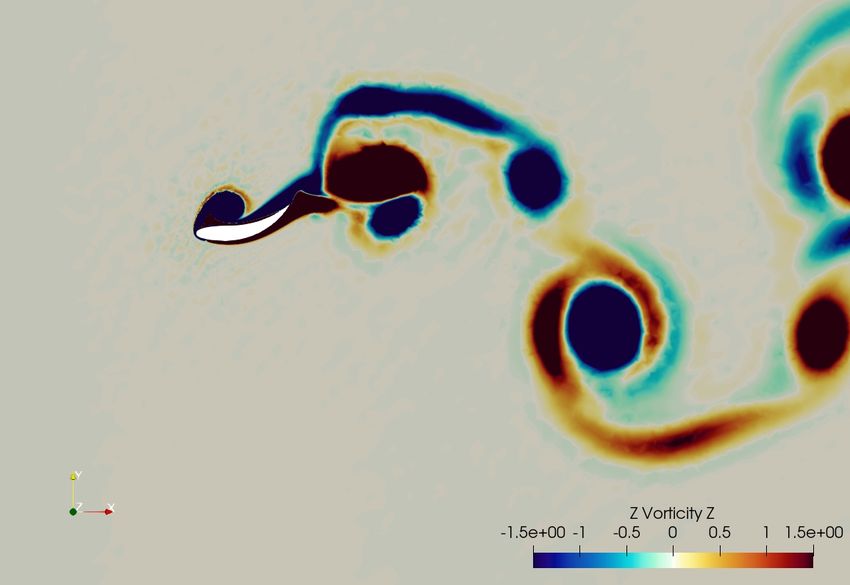
(a) t/T = 0.18

                                (a)

                                                                                               (b) t/T = 0.25

                                (b)

FIGURE 13: VARIATION OF CT OVER A TIME PERIOD FOR
(a) MORPH POSITION OF 0%, AND (b) MORPH AMPLI-
TUDE OF 50◦

upper surface of the foil during the downstroke and is fully de-
veloped around t/T = 0.35. Comparing the two cases, we notice
that the trailing edge of the foil morphs to a larger extent for the                           (c) t/T = 0.35
case of 50◦ amplitude, delaying the shedding of the LEV gener-
ated during downstroke. Thus, a suction pressure is maintained             FIGURE 14: PRESSURE AND VORTICITY CONTOURS FOR
over the upper surface for a larger duration during downstroke             THE MORPHING FOIL WITH MORPH POSITION OF 0%
compared to the 10◦ case (Fig. 14(c)). Consequently, the above             AND MORPH AMPLITUDE OF 10◦ (LEFT COLUMN) AND
pressure differential leads to higher thrust for 50◦ case compared         50◦ (RIGHT COLUMN) AT TIME INSTANCES (a) t/T = 0.18,
to 10◦ morph amplitude (Fig. 13(a)).                                       (b) t/T = 0.25 AND (c) t/T = 0.35
     Therefore, the influence of morph amplitude on the propul-

                                                                       9                                Copyright © 2022 by ASME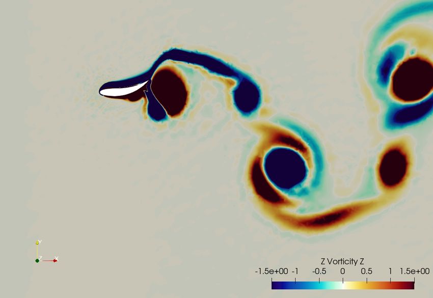
sive performance of the morphing foil is an interplay between the
increase in the projected area of the foil to the incoming flow and
the phenomenon of delayed shedding of the LEV.
     These observations hold when viewed in isolation with just
morph amplitude as the variable quantity. Since the study is not
in isolation, certain deviations from this trend due to morph po-
sition are observed, one being the deviation from the pattern of
increasing CT,mean with increasing morph amplitude, at higher
morph positions (Fig. 6(a)). This is discussed in the subsequent
sub-section.

Effect of Morph Position
     To further extend our discussion to the effect of morph po-
sition, we consider the representative case with fixed morph am-
plitude of 50◦ and compare the morph positions of 0% and 30%.                                    (a) t/T = 0.15
     The pressure and vorticity contours for the two representa-
tive cases are shown in Fig. 15. The morphing near the leading
edge of the foil for 0% morph position imparts an absolute ve-
locity opposite to the heave velocity. Morphing at low positions
of 0% allow the foil surface to move closer to the vortex and pre-
vent its separation, resulting in higher thrust generation. This is
reflected in Fig. 13(b), where CT continues to increase up to the
mid-point of the downstroke, where morph is highest, dropping
subsequently as the foil reduces the trailing edge morph. How-
ever, at higher morph positions, the trailing edge is too far behind
to meet the vortex at the point of separation. Since there is no
morphing till 30% of chord in the representative case considered,
the leading 30% of the foil is purely heaving. The higher abso-
lute velocity solely due to heaving is encouraging separation, and
simultaneously, the morphed trailing edge is too far away from                                   (b) t/T = 0.24
the vortex.
     Only the morphed section of the foil contributes to the
change in projected area in the streamwise direction, thus re-
sulting in the favorable pressure difference across the morphed
section which propels the foil. The trailing edge of the foil (the
section that is morphing) loses the influence of the LEV-ds(n)
earlier with higher morph position. The reason why CT,mean also
does not increase with amplitude at higher positions is because
the morphed section of the foil is too far from the vortex to have
any noticeable effect.
     We observed that morphing facilitates the transit and influ-
ence of the vortex on the foil by keeping it attached although it
delays the shedding of the vortex.

                                                                                                 (c) t/T = 0.34
CONCLUSIONS AND FUTURE WORK
      An extensive numerical study is carried out to understand the         FIGURE 15: PRESSURE AND VORTICITY CONTOURS FOR
enhancement in propulsive performance due to the inverse von-               THE MORPHING FOIL WITH MORPH AMPLITUDE 50◦
Kárman vortex street effect in a combined morphing and heaving             AND MORPH POSITION OF 0% (LEFT COLUMN) and 30%
foil. The key findings from the present study are:                          (RIGHT COLUMN) AT TIME INSTANCES: (a) t/T = 0.15, (b)
                                                                            t/T = 0.24 and (c) t/T = 0.34
 1. The coefficient of thrust (CT ) depends on both, the morph

                                                                       10                                 Copyright © 2022 by ASME
position and the morph amplitude. Higher amplitudes are [8] Lighthill, S. J., 1975. Mathematical Biofluiddynamics. So-
generally observed to have a positive impact on increasing ciety for Industrial and Applied Mathematics.
CT , while higher positions generally have a negative impact [9] Knoller, R., 1909. “Die gesetze des luftwiderstandes”. Flug
on CT . -Und Motortechnik(Wien), 3(21), pp. 1 – 7.
2. The lift (CL ) profile is dependent on the αe of the motion, [10] Wu, X., Zhang, X., Tian, X., Li, X., and Lu, W., 2020. “A
and the trend is resultant of the positive impact of morph am- review on fluid dynamics of flapping foils”. Ocean Engi-
plitude (CL increases with increasing morph amplitude) and neering, 195, p. 106712.
the negative impact of morph position (CL decreases with [11] Akhtar, I., Mittal, R., V., L. G., and Drucker, E., 2007. “Hy-
increasing morph position). drodynamics of a biologically inspired tandem flapping foil
3. Propulsive efficiency (η) also faces the same impact of configuration”. Theoretical and Computational Fluid Dy-
morph amplitude and position as does CL and CT . namics, 21, pp. 155–170.
4. Higher amplitudes of morphing has a higher projected area [12] Rival, D., Schönweitz, D., and Tropea, C., 2011. “Vor-
in the streamwise direction, and the vortex remains closer to tex interaction of tandem pitching and plunging plates: a
the surface of the foil for a longer duration. CT,mean is thus two-dimensional model of hovering dragonfly-like flight”.
higher with higher morph amplitude. Bioinspiration & Biomimetics, 6(1), feb, p. 016008.
5. An increase in morph position leads to decrease in CT , be- [13] Broering, T. M., Lian, Y., and Henshaw, W., 2012. “Nu-
cause the LEV separates too early and the morphed trailing merical investigation of energy extraction in a tandem flap-
edge is not influenced by the suction pressure created by the ping wing configuration”. AIAA Journal, 50(11), pp. 2295–
vortex. 2307.
[14] Lin, X., Wu, J., Zhang, T., and Yang, L., 2019. “Phase
Considering the effect of pitching as well so that a combina- difference effect on collective locomotion of two tandem
tion of the three, viz., heave, pitch and morph, tend to physically autopropelled flapping foils”. Phys. Rev. Fluids, 4, May,
realize the biological flexible flapping motion is a topic of fu- p. 054101.
ture study. Effect of Reynolds number can also be investigated, [15] Sampath, K., Geder, J. D., Ramamurti, R., Pruessner,
extending the work to turbulent regime. M. D., and Koehler, R., 2020. “Hydrodynamics of tandem
flapping pectoral fins with varying stroke phase offsets”.
Phys. Rev. Fluids, 5, Sep, p. 094101.
REFERENCES [16] Kinsey, T., and Dumas, G., 2012. “Optimal tandem config-
[1] Chen, Y., Zhan, J., Wu, J., and Wu, J., 2017. “A fully- uration for oscillating-foils hydrokinetic turbine”. Journal
activated flapping foil in wind gust: Energy harvesting per- of Fluids Engineering, Transactions of the ASME, 134(3).
formance investigation”. Ocean Engineering, 138, pp. 112 cited By 71.
– 122. [17] Karbasian, H., Esfahani, J., and Barati, E., 2015. “Simu-
[2] Bøckmann, E., and Steen, S., 2016. “Model test and simu- lation of power extraction from tidal currents by flapping
lation of a ship with wavefoils”. Applied Ocean Research, foil hydrokinetic turbines in tandem formation”. Renew-
57, pp. 8 – 18. able Energy, 81, pp. 816 – 824.
[3] Triantafyllou, G. S., Triantafyllou, M. S., and Grosen- [18] Pan, D., Deng, J., Shao, X., and Liu, Z., 2016. “On the
baugh, M. A., 1993. “Optimal thrust development in os- propulsive performance of tandem flapping wings with a
cillating foils with application to fish propulsion”. Journal modified immersed boundary method”. International Jour-
of Fluids and Structures, 7(2), pp. 205 – 224. nal of Computational Methods, 13(5). cited By 14.
[4] An Overview of Micro Air Vehicle Aerodynamics. pp. 1–10. [19] Muscutt, L. E., Weymouth, G. D., and Ganapathisubra-
[5] Kota, S., Hetrick, J. A., Osborn, R., Paul, D., Pendleton, mani, B., 2017. “Performance augmentation mechanism of
E., Flick, P., and Tilmann, C., 2003. “Design and ap- in-line tandem flapping foils”. Journal of Fluid Mechanics,
plication of compliant mechanisms for morphing aircraft 827, p. 484–505.
structures”. In Smart Structures and Materials 2003: In- [20] Ma, P., Wang, Y., Xie, Y., Han, J., Sun, G., and Zhang, J.,
dustrial and Commercial Applications of Smart Structures 2019. “Effect of wake interaction on the response of two
Technologies, E. H. Anderson, ed., Vol. 5054, International tandem oscillating hydrofoils”. Energy Science & Engi-
Society for Optics and Photonics, SPIE, pp. 24 – 33. neering, 7(2), pp. 431–442.
[6] Kota, S., U.S. Patent 5 971 328, 1999. System for varying [21] Joshi, V., and Mysa, R. C., 2021. “Hydrodynamic analy-
a surface contour, Oct. sis of tandem flapping hydrofoils”. In ASME 40th Interna-
[7] Betz, A., 1912. “Ein beitrag zur erklarung des segelfluges”. tional Conference on Ocean, Offshore and Arctic Engineer-
Zeitschrift Fur Flugtechnik Und Motorluftschiffart, 3, ing (OMAE).
pp. 269 – 272. [22] Joshi, V., and Mysa, R. C., 2021. “Mechanism of wake-
11 Copyright © 2022 by ASMEinduced flow dynamics in tandem flapping foils: Effect of aerostructural optimization”. Aerospace Science and Tech-
the chord and gap ratios on propulsion”. Physics of Fluids, nology.
33(8), p. 087104. [34] Eguea, J. P., Pereira Gouveia da Silva, G., and Martini Cata-
[23] Heathcote, S., Martin, D., and Gursul, I., 2004. “Flexi- lano, F., 2020. “Fuel efficiency improvement on a business
ble flapping airfoil propulsion at zero freestream velocity”. jet using a camber morphing winglet concept”. Aerospace
AIAA Journal, 42(11), pp. 2196–2204. Science and Technology, 96, Jan., p. 105542.
[24] Li, D., Zhao, S., Da Ronch, A., Xiang, J., Drofelnik, J., [35] Chung, J., and Hulbert, G. M., 1993. “A time integration
Li, Y., Zhang, L., Wu, Y., Kintscher, M., Monner, H. P., algorithm for structural dynamics with improved numerical
Rudenko, A., Guo, S., Yin, W., Kirn, J., Storm, S., and dissipation: The generalized-α method”. Journal of Ap-
Breuker, R. D., 2018. “A review of modelling and analysis plied Mechanics, 60(2), pp. 371–375.
of morphing wings”. Progress in Aerospace Sciences, 100, [36] Jaiman, R. K., and Joshi, V., 2022. Computational Mechan-
pp. 46–62. ics of Fluid-Structure Interaction, 1 ed. Springer.
[25] Pankonien, A. M., and Inman, D. J., 2015. “Spanwise mor-
phing trailing edge on a finite wing”. In Active and Passive
Smart Structures and Integrated Systems 2015, W.-H. Liao,
ed., Vol. 9431, International Society for Optics and Photon-
ics, SPIE, pp. 248 – 262.
[26] Lyu, Z., and Martins, J. R. R. A., 2015. “Aerodynamic
shape optimization of an adaptive morphing trailing-edge
wing”. Journal of Aircraft, 52(6), pp. 1951–1970.
[27] Scheller, J., Chinaud, M., Rouchon, J., Duhayon, E., Cazin,
S., Marchal, M., and Braza, M., 2015. “Trailing-edge dy-
namics of a morphing naca0012 aileron at high reynolds
number by high-speed piv”. Journal of Fluids and Struc-
tures, 55, 02.
[28] Jodin, G., Motta, V., Scheller, J., Duhayon, E., Döll, C.,
Rouchon, J., and Braza, M., 2017. “Dynamics of a hy-
brid morphing wing with active open loop vibrating trailing
edge by time-resolved piv and force measures”. Journal of
Fluids and Structures, 07.
[29] Tô, J.-B., Simiriotis, N., Marouf, A., Szubert, D., Asprou-
lias, I., Zilli, D., Hoarau, Y., Hunt, J., and Braza, M., 2019.
“Effects of vibrating and deformed trailing edge of a mor-
phing supercritical airfoil in transonic regime by numerical
simulation at high reynolds number”. Journal of Fluids and
Structures, 91, p. 102595.
[30] Zhang, J., Shaw, A., Wang, C., Gu, H., Amoozgar, M.,
Friswell, M., and Woods, B., 2021. “Aeroelastic model and
analysis of an active camber morphing wing”. Aerospace
Science and Technology, 111, Apr.
[31] Simiriotis, N., Jodin, G., Marouf, A., Elyakime, P., Hoarau,
Y., Hunt, J., Rouchon, J., and Braza, M., 2019. “Morphing
of a supercritical wing by means of trailing edge deforma-
tion and vibration at high reynolds numbers: Experimental
and numerical investigation”. Journal of Fluids and Struc-
tures, 91, 07.
[32] Hang, X., Su, W., Fei, Q., and Jiang, D., 2020. “Analyti-
cal sensitivity analysis of flexible aircraft with the unsteady
vortex-lattice aerodynamic theory”. Aerospace Science and
Technology, 99, p. 105612.
[33] Burdette, D. A., and Martins, J. R., 2018. “Design of a
transonic wing with an adaptive morphing trailing edge via
12 Copyright © 2022 by ASMEYou can also read


