Test influence of screen thickness on double-N six-light-screen sky screen target
←
→
Page content transcription
If your browser does not render page correctly, please read the page content below
Open Physics 2022; 20: 1–8
Research Article
Hai Li, Jinping Ni, Xiaodong Yang*, and Qunfeng Dong
Test influence of screen thickness on double-N
six-light-screen sky screen target
https://doi.org/10.1515/phys-2022-0010 gravity [5] and medium [6], the test method and parameter
received December 22, 2021; accepted January 21, 2022 treatment method [7,8] have always been the focus of the
Abstract: In this article, a new method for processing research.
trajectory parameter tests of flying targets with the geo- The diversity in light-screen targets contributes to the
metric center of the screen as the response time of the further optimization of the structure and accuracy. At present,
detector is proposed. The superiority of this method over many types of light-screen test models have been produced,
the conventional method for uniform thickness treatment such as light-screen targets with integrated transceiver [9],
is shown through the error and data analysis of the yaw intelligent light-screen targets [10], and composite light-
angle, pitch angle, and flying speed. The relative distance screen targets [11]. Sky screen targets are the passive light
between the test track and the real track shows the accu- source test instrument that use natural light background
racy of the new method. The obvious statistical rules can to detect the flying target. In terms of the double-N six-
be found for the errors of test parameters, which is con- light-screen sky screen target [12], the measurement of
ducive to the test research of random and violent vibra- intensity of multitarget target fall and the operation
tions of the target surface. vector can be actualized, and the test method is simple
and reliable. After the test, the operating parameters [13]
Keywords: flying target, yaw angle, pitch angle, running of the flying target can be obtained immediately.
speed, sky screen target At present, the data processing method of the six-
light-screen sky screen target is not perfect. However,
as the analysis method gradually deepened, the test
accuracy is improved. The system has two typical proces-
1 Introduction sing approximations, that is, the thickness of each screen
is considered to be uniform and the speed of the move-
The flying target test plays an important role in aerospace
ment of the flying target is even between adjacent screens.
[1,2], military matters [3,4], and other fields. The flying
Only by effectively solving these two approximation diffi-
target test includes the inner orbit test, intermediate orbit
cult problems can the trajectory parameters of the flying
test, and final orbit test, of which the intermediate orbit
target be measured with high accuracy. This study aims to
test is the most essential link of the flying test with the
optimize the first approximation and proposes a hypoth-
longest time and the most influenced by external factors.
esis in accordance with the uniform increase of the screen
Flight trajectory and operating speed are the important
thickness. The processing was conducted with the geo-
factors of the intermediate orbit test, which can directly
metric center of the screen as the response time, and the
reflect the target fall attribute of the moving target. During
method was verified through simulation, operation, and field
the operating process, in addition to the interference of
experiment, providing the theoretical basis for achieving the
test system of target fall with paperless targets.
* Corresponding author: Xiaodong Yang, Xianyang Normal
University, College of Physics and Electronic Engineering, Wenlin
Road, Weicheng District, Xianyang City, Shaanxi Province, 712000,
China, e-mail: kevin09409@sina.com 2 Methodology
Hai Li, Jinping Ni: Xi’an Technological University, School of
Optoelectronics and Engineering, University Middle Road No. 2,
The test system of sky screen is to place a photoelectric
Weiyang District, Xi’an, Shaanxi Province, 710021, China
Qunfeng Dong: Xianyang Normal University, College of Physics and
detector directly below the trajectory of the flying target
Electronic Engineering, Wenlin Road, Weicheng District, Xianyang to be tested to form a detection screen with natural light
City, Shaanxi Province, 712000, China as a background light source. The circuit corresponding
Open Access. © 2022 Hai Li et al., published by De Gruyter. This work is licensed under the Creative Commons Attribution 4.0 International
License.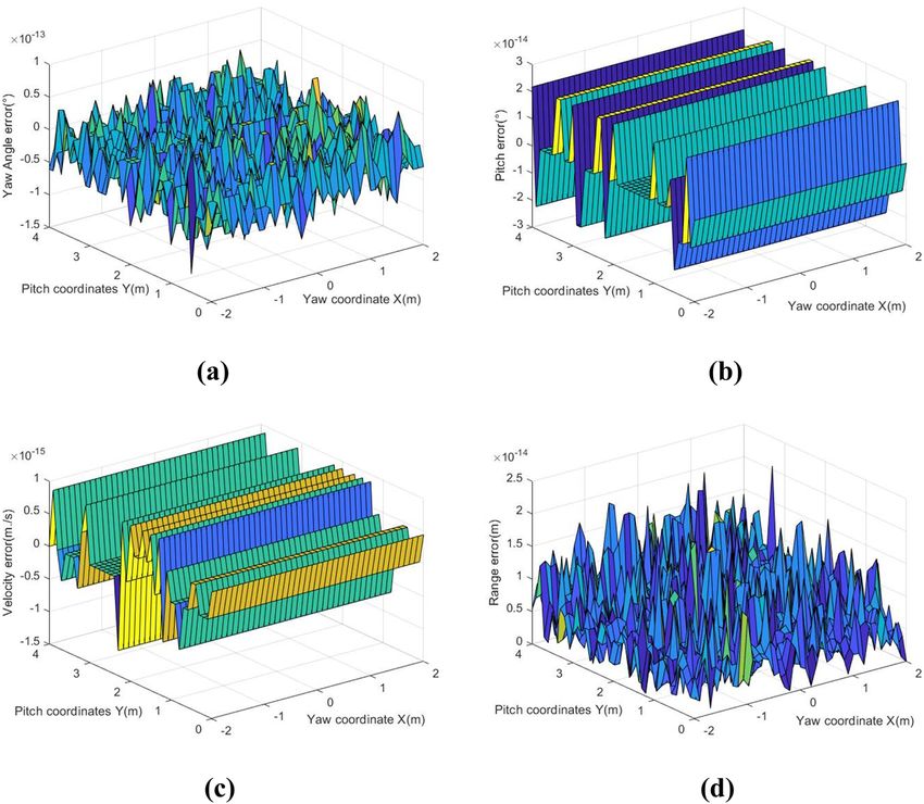
2 Hai Li et al.
to each detection sky screen will output an over-target instantaneous value of the flying target passing through the
signal to then obtain all analog signals of the flying target screen. When the flying target passed through the first
through signal data acquisition instrument. The corre- screen with normal incidence, the error analysis of the
sponding time pulse signals will be obtained after proces- test parameters was conducted with the conventional treat-
sing. Finally, the position coordinates and speed of target ment method, as shown in Figure 2.
fall will be calculated further by computer to transmit the It could be seen that the yaw angle error processed
data to the master computer terminal with test results with uniform thickness in the two-dimensional target
displayed. The double-N six-light-screen sky screen target surface coordinates was within the range of ±1 × 10⁻¹³
is composed of two three-light-screen target groups [13]. degrees, and the fluctuation uniformity was relatively
When the flying target passed through the double-N six- stable. The pitch angle error was not affected by the yaw
light-screen test system, six groups of pulse signals were coordinates, but as the pitch coordinates increased, the
generated, respectively, through the light screen and to pitch angle error tended to increase as a whole. In addi-
calibrate the passing time, as shown in Figure 1. tion, the fluctuation range of pitch coordinates within 4 m
When six passing moments t1, t2 , t3 , t4 , t5 , and t6 were was within ±4 × 10⁻¹⁴ degrees. Both the speed error and
obtained from left to right, the test pitch angle θ , the test the relative distance error were not affected by the yaw
azimuth angle γ , and the test speed v of the flying target coordinates, and the speed error increased slightly with
could be derived, respectively, by using the principle of the increase of pitch coordinates. In addition, the fluctua-
geometric optics: tion center of the overall error was 5 × 10⁻¹⁶ m/s, and the
regularity of fluctuation was relatively poor. The relative dis-
t6 − t4 − t3 + t1
θ = arctan⎡ cos γ⎤ (1) tance error was directly proportional to the pitch angle coor-
⎢
⎣ 6 t4 − t3 − t1)tan α
( t + ⎥
⎦ dinates, which was obviously undesirable in the relatively
t −t high flight test area. If the screen system was applied to the
γ = arctan⎡ 6 3 cot β (1 − tan α tan δ ) − cot β⎤ (2)
⎢ t5 − t2 ⎥ highly variable environment, such as mountains and oceans,
⎣ ⎦
it would bring certain troubles to the flight trajectory test.
Lcos α cos δ When the flying target passed through the first screen
v= (3)
(t6 − t3)cos θ cos γ cos(α + δ ) with oblique incidence, the same conventional method
where α referred to the angle between adjacent light for pulse median treatment was used to analyze the error
screens at the pitch projection plane and β referred to for the test parameters, as shown in Figure 3.
the angle between adjacent light screens at the azimuth It was obvious that the errors of each parameter of
projection plane. There were four angles for each type of oblique incidence were much larger than those of normal
angle, and they were designed as equal symmetrical incidence, and the fluctuation range was wider. As the
structures for the convenience of calculation. δ referred pitch angle increased, the yaw angle error would also
to the angle between the preselected orbit of the flying increase, and the influence of the yaw direction on the
target and the pitch plane, and L referred to the distance yaw angle error was more significant. In addition, the
between two sky screen target groups. yaw direction had a weak influence on the pitch angle
In the treatment process of the test system, it is error; however, the larger the pitch angle, the larger the
usually considered that the screen thickness is uniform pitch angle error. When the pitch angle was zero, which
with the median of the response pulse of the detector as the was referred to as a normal incidence, the pitch angle
error was relatively small, which was consistent with
the law reflected in Figure 2(b). The influence degree of
the yaw direction on the speed error was similar to that
of the pitch direction, both experiencing the same increase
and decrease of value in small range. The degree of the
yaw direction had no obvious influence on the relative
distance error, but as the pitch angle increased, the
relative distance error would also significantly increase.
In addition, the error fluctuation slope slowly increased.
During the analysis of the flight trajectory, the pitch angle
factor should be prioritized in the error compensation.
In accordance with the simulated result, it could be
Figure 1: Screen side view of double-N six-light-screen. seen that the errors of the measured data were not stable
Test influence of screen thickness on double-N sky screen target 3
Figure 2: Parameter error of uniform thickness in normal incidence: (a) error between the yaw angle and set true value, (b) error between
pitch angle and set true value, (c) error between the speed and set true value, and (d) error between the relative distance and set true value.
regardless of normal incidence or oblique incidence. The slit aperture and the photoelectric detector were
Especially the influence of pitch coordinates on the test 30 mm in length. A detection field angle of 60° was
errors was more obvious, which was one of the reasons formed jointly by the optical lenses and the slit aperture.
why the target fall error of the flying target might reach Affected by the width of the aperture slit, there was a
several centimeters. It could be seen that although the certain thickness for the cross section of the field, and
responsive time to the pulse was rather short, the selec- it increased with the growth of the height, as shown in
tion of the effective instantaneous value in the interval Figure 4.
was very important. If the thickness changes of the screen were consid-
ered and the installation of the sky screen target groups
were not in the same plane, the treatment of test response
time with the pulse center would be further discussed.
3 Experimental procedures A bold assumption was made here. When the edge dif-
fraction and scattering phenomena were ignored, the
In the actual test process, Nikon lenses with focal length geometric center surface of each screen should be taken
of 24 mm were adopted for the optical lenses of system. as the response time of the test. Then, the data was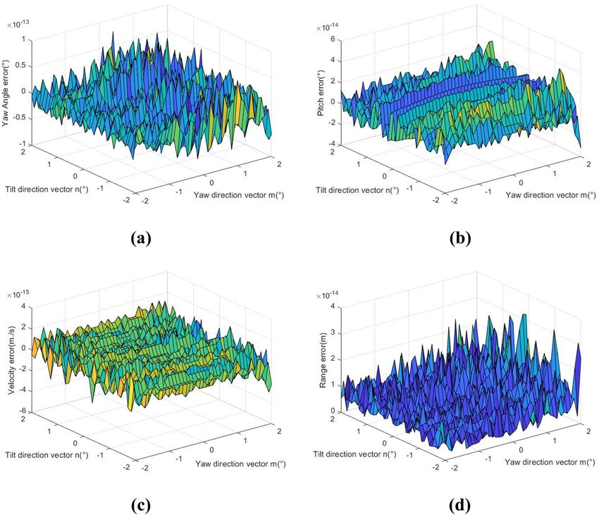
4 Hai Li et al.
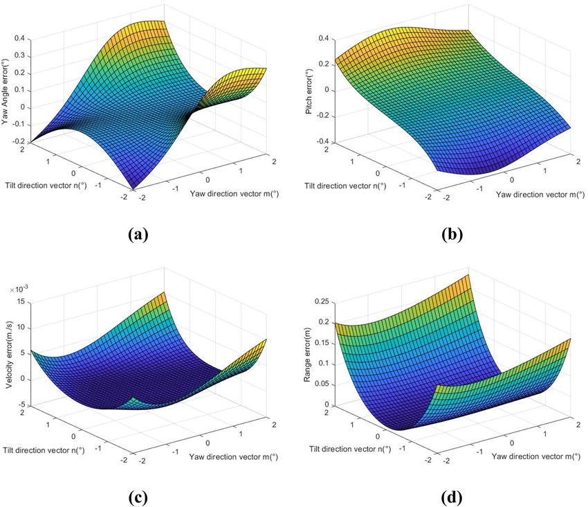
Figure 3: Parameter error of uniform thickness in oblique incidence: (a) error between the yaw angle and set true value, (b) error between
pitch angle and set true value, (c) error between the speed and set true value, and (d) error between the relative distance and set true value.
60°
Lens Lens
A slit aperture at Rotate 90°
A slit aperture at
the image surface the image surface
Figure 4: Schematic of the field thickness of detected by the sky screen target.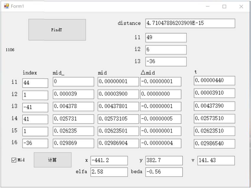
Test influence of screen thickness on double-N sky screen target 5
traversed in the forward and backward time regions with of the yaw angle was within the range of ±0.5 × 10⁻¹³
the pulse center, and the orbit parameters of the simula- degrees, and the overall fluctuation was more balanced.
tion test were compared with the set orbit parameters. The pitch angle error and the speed error were still mainly
The smaller the average error, the better the test effect. affected by the pitch coordinates, but when compared with
In the system, the front and rear screens and geometric the uniform thickness, the error fluctuation range did
center screens of the six light screens could form 18 screen not increase. The pitch angle error was near ±2 × 10⁻¹⁶
structures, respectively, and the respective equations of degrees, and the center of the overall speed error was
planes were established for analysis. When the flying target 0 m/s with the approximation fluctuation within the range
passed through the first screen with normal incidence, the of ±1 × 10⁻¹⁵ m/s. The fluctuation of the relative distance error
simulated analysis was conducted for the test parameter was within 2 × 10⁻¹⁴ m , which was several orders of magni-
errors after traversal operation, as shown in Figure 5. tude better than the uniform thickness. In addition, it showed
It could be seen from the above figures that the test typical statistical distribution characteristics, which is con-
parameters involving the changes of the screen thickness ducive to the later data compensation analysis.
were much smoother than the error fluctuation of uniform When the flying target passed through the first screen
thickness approximation. The overall error fluctuation with oblique incidence, the simulated analysis for the test
Figure 5: Parameter error of nonuniform thickness in normal incidence: (a) error between the yaw angle and set true value, (b) error between
pitch angle and set true value, (c) error between the speed and set true value, and (d) error between the relative distance and set true value.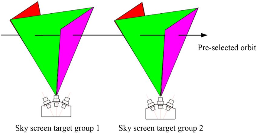
6 Hai Li et al. Figure 6: Parameter error of nonuniform thickness in oblique incidence: (a) error between the yaw angle and set true value, (b) error between pitch angle and set true value, (c) error between the speed and set true value, and (d) error between the relative distance and set true value. Table 1: Data statistics of field tests S/N t2/µs t3/µs t4/µs t5/µs t6/µs xB yB xPC yPC v / ms−1 θ/° γ /° 1 2.811 4.79 24.914 27.668 29.406 162 −110 152.9 692 145.6 −0.6 0.2 2 1.542 4.818 25.794 27.117 29.812 −198 −218 −220.1 579.7 142.1 −1.8 0.7 3 1.158 5.951 24.633 26.263 31.025 −448 206 −488.1 1023.4 145 1.4 0.9 4 3.206 5.765 25.104 28.643 31.378 140 180 125.4 986.8 142.1 1.5 0.1 5 2.553 3.977 26.53 29.415 30.426 301 −233 293.7 564.1 136.2 −0.1 1.6 6 1.854 3.137 24.714 26.584 28.008 69 −277 58.4 518 145.5 0.5 −0.5 7 2.177 6.024 28.118 30.845 34.083 −27 23 −50.2 823.5 128.4 0.1 2.2 8 1.114 6.006 27.31 29.289 33.805 −292 125 −330.3 936.9 130.9 1.4 2.4 9 2.825 7.19 28.17 31.444 35.773 −122 255 −138.1 1061 127 1.2 0.7 10 0.039 4.378 25.731 26.235 29.869 −411 −182 −456.3 615.6 140.9 −0.4 2.5
Test influence of screen thickness on double-N sky screen target 7
inconspicuous height changes, the appropriate mean
value could be selected for analyzing and processing
the flight trajectory.
To verify the simulation result, sunny days were
selected to conduct the experiment in the outfield. The
distance between two sky screen groups was arranged to
be 3,600 mm, and the height difference of vertical target
groups was ΔH = 10 mm . Ten groups of test parameters
were calibrated and processed, respectively, as shown in
Table 1.
The passing time of the first screen was arranged to be
0, and xB and yB referred to horizontal and vertical coordi-
nates of paper targets. In addition, xPC , yPC , v , θ , and γ ,
respectively, refer to horizontal and vertical coordinates,
speed, pitch angle, and azimuth angle processed with pulse
Figure 7: Operation interface of experimental data traversal.
median. Traversal operation was conducted for each group
of passing time to seek the minimum relative distance
parameter errors after traversal operation was conducted, between the simulated running orbit and the experimental
as shown in Figure 6. orbit. The operation interface is shown in Figure 7.
As can be seen from the above figures, the error fluc- Traversal processing was conducted for ten groups of
tuation of all parameters was much more stable than the data from the experiment to obtain the optimal target
range of the uniform thickness treatment method, achieving flying speed v2 , the pitch angle θ 2 , and the azimuth angle
significant improvement in the overall error. In addition, γ2 . The operating trajectory fitted by this group of para-
the yaw coordinates and pitch coordinates would not cause meter values coincides with the operating trajectory with
fluctuations in the parameter error. The fluctuation of the geometric center surface of each screen as the response
the yaw angle error was within the range of ±0.8 × 10⁻¹³ time, indicating that the previous conjecture is reasonable.
degrees, and the center of the pitch angle error was To better observe the degree of improvement of the test
0.5 × 10⁻¹⁴ degrees with the fluctuation within the range accuracy, statistics was conducted for the data difference,
of ±2.5 × 10⁻¹⁴ degrees. The error fluctuation of two angles as shown in Table 2.
involving the screen thickness was about 1014 times higher Where, Δx and Δy referred to the difference values
than the error fluctuation with uniform thickness. The between horizontal and vertical coordinates processed
fluctuation of the speed error was within the range of with the pulse median and horizontal and vertical coor-
±2 × 10⁻¹⁵ m/s with improvement of about 1013 times. dinates of paper targets. Δx′ and Δy′ referred to the differ-
The small increase next to 2 × 10⁻¹⁴ m occurs for the ence values between horizontal and vertical coordinates
relative distance error with the increase of yaw coordi- with optimal processing of traversal and horizontal and
nates and pitch coordinates. In the test heights of the vertical coordinates of paper targets. Δv , Δθ , and Δγ , respec-
common flying targets, the relative distance error did tively, referred to the difference values of the speed, the
not exceed 4 × 10⁻¹⁴ m. In the test environment with pitch angle, and the azimuth angle of the two processing
Table 2: Data statistics of traversal operation processing
S/N xPC2 yPC2 v2/ ms−1 θ 2/ ° γ2/ ° Δx Δx ′ Δy Δy ′ Δv / ms−1 Δθ / ° Δγ / °
1 159 459.5 146.1 −0.68 0.39 9.1 3 −802 −569.5 0.5 −0.08 0.19
2 −218.1 353.2 142.62 −1.91 0.77 22.1 20.1 −797.7 −571.2 0.52 −0.11 0.07
3 −480.9 782.4 145.55 1.27 0.96 40.1 32.9 −817.4 −576.4 0.55 −0.13 0.06
4 132.2 745.3 142.65 1.39 0.26 14.6 7.8 −806.8 −565.3 0.55 −0.11 0.16
5 295.4 329.8 136.67 −0.2 1.72 7.3 5.6 −797.1 −562.8 0.47 −0.1 0.12
6 66.2 280.2 145.98 0.35 −0.36 10.6 2.8 −795 −557.2 0.48 −0.15 0.14
7 −43.6 589.8 128.88 −0.02 2.37 23.2 16.6 −800.5 −566.8 0.48 −0.12 0.17
8 −318.2 697.2 131.41 1.23 2.51 38.3 26.2 −811.9 −572.2 0.51 −0.17 0.11
9 −137.7 822.7 127.45 1.09 0.84 16.1 15.7 −806 −567.7 0.45 −0.11 0.14
10 −441.2 382.7 141.43 −0.56 2.58 45.3 30.2 −797.6 −564.7 0.53 −0.16 0.088 Hai Li et al.
methods. As can be seen from the above table, the coordi- Author contributions: All authors have accepted respon-
nate data with the geometric center of the screen as the sibility for the entire content of this manuscript and
response time was obviously closer to the data of paper approved its submission.
targets, and the experiment was in line with the theoretical
analysis. Therefore, there is a reason to believe that the data Conflict of interest: The authors state no conflict of interest.
in the last three columns of Table 2, to some extent, reflect
the optimization range of the processing method with the
geometric center of the screen as the response time com-
pared with the processing method of pulse median. References
[1] Clainche SL, Moreno-Ramos R, Taylor P, Vega JM. New robust
4 Conclusion method to study flight flutter testing. J Aircr. 2019;56(1):336–43.
[2] Thedin R, Kinzel MP, Horn JF, Schmitz S. Coupled simulations
of atmospheric turbulence-modified ship airwakes and heli-
If the thickness of the screen surface is considered and copter flight dynamics. J Aircr. 2019;56(2):812–24.
the geometric center of each screen is used to define the [3] Chen T, Huang W, Zhang W. Experimental investigation on
response time of the flying target trajectory, the accuracy trajectory stability of high-speed water entry projectiles.
of the processing results of the yaw angle, the pitch angle, Ocean Eng. 2019;175(1):16–24.
[4] Mirzaei M, Taghvaei H, Alishahi MM. Mathematical modeling
and speed is significantly improved compared with the
of the oblique water-entry of cylindrical projectiles. Ocean
case of uniform thickness. In addition, the fluctuation
Eng. 2020;205(1):107257.
range of the parameter errors significantly decreased, [5] Tian H, Ni JP, Jiao MX. Projectile flying parameter measurement
showing good probability statistics. The relative distance model of parabolic trajectory and precision analysis. Chin J Sci
error between the measured trajectory and the true value Instrum. 2016;37(1):8.
can also directly reflect the test superiority with the screen [6] Zhu H, Sun Q, Liu X, Chen Z. Fluid–structure interaction-based
aerodynamic modeling for flight dynamics simulation of par-
thickness considered. In this article, the traversal opera-
afoil system. Nonlinear Dyn. 2021;104(6):1–22.
tion method was adopted to conduct data analysis, and [7] Lu J, Du P, Tan S, Li X. Interior ballistic characteristics of
the theoretical result was verified through the field experi- electromagnetic rail launcher under continuous firing. IEEE
ment data. The high consistency of the results was main- Trans Ind Appl. 2020;99:1.
tained. The processing method can effectively improve the [8] Chen SH, Souna AJ, Soles CL, Stranick SJ, Chan EP. Using
microprojectiles to study the ballistic limit of polymer thin
speed of the flying target and the test accuracy of the run-
Films. Soft Matter. 2020;16(16):1–6.
ning trajectory, providing effective theoretical basis and
[9] Shi L. Research on the technology of integrated receiving-
feasible means for the dynamic test system. transmitting laser screens. Xi’an: Xi’an Technological
The parameter errors were observed from the per- University; 2010.
spective of the statistical law, and the test parameter [10] Zhang YW, Zhang S, Zhang MY, Zhang HZ. Intelligent light
processing method with the screen thickness considered screen target coordinate measurement system.
CN210570247U; 2020.
can be applied to the situations where the heights and
[11] Li H, Ni JP, Yang XD, Wu ZC. Analysis of the structure and
angles of target fall targets are variables, providing effec- properties of triangular composite light-screen targets. Open
tive processing methods for the dynamic target surface Phys. 2021;19(1):583–89.
test under complex environment such as strong vibration [12] Chen R, Ni JP, Liu J. Uncertainty analysis of coordinate mea-
and oceans. surement of six-light-screen array sky screen vertical target
based on engineering model. Acta Armamentarii.
2019;40(3):612–20.
Funding information: This study is supported by the Key
[13] Ni JP. Technology and application of measurement of the light
Cultivation Project of Scientific Research Program of screen array. Bei Jing: National Defense Industry Press; 2014.
Xianyang Normal University (Grant No. XSYK21040). p. 176–85.You can also read