CONTROLLING MINI EXHAUST FAN THROUGH ANDROID-BASED SMARTPHONE FOR IOT-BASED SMART HOME SYSTEM
←
→
Page content transcription
If your browser does not render page correctly, please read the page content below
TEM Journal. Volume 10, Issue 3, Pages 1301‐1306, ISSN 2217‐8309, DOI: 10.18421/TEM103-37, August 2021.

 Controlling Mini Exhaust Fan through
 Android-Based Smartphone for
 IoT-Based Smart Home System
 Syifaul Fuada 1, Maulana Yusuf Fathany 2, Trio Adiono 3, Khilda Afifah 4
 1
 Program Studi Sistem Telekomunikasi, Universitas Pendidikan Indonesia, Bandung, Indonesia
 2,3
 The University Center of Excellence on Microelectronics, Institut Teknologi Bandung, Indonesia
 4
 Department of Function Control Systems, Shibaura Institute of Technology, Tokyo, Japan

 Abstract – In this work, we present a control system 1. Introduction
for a mini electrical fan. The aim of this work is to
design a controller prototype for an electrical fan Electrical fan is one of the commonly used
within the smart home system. The system consists of electronic appliance devices for air control,
an STM32L100 microcontroller for controlling the especially in the home environment. While not as
electrical fan using pulse-width modulation (PWM),
 potent as other electronic appliances such as air
TIP 102 BJT transistor for ‘off,’ and ‘on’ control of the
fan, and 1N4007 fly-back diode. The PWM is conditioner for temperature control, electrical fan has
generated by the STM32L100 microcontroller to overall lower electricity cost and more
control the Fan’s speed softly (25%, 50%, 75%, and environmentally-friendly nature due to not producing
0% - 100% of speed). In addition, the system is potentially dangerous substances for ozone layer. As
equipped with a ZigBee module to support wireless such, electrical fan remains widely used, especially
communication with the host, which is required to in residential areas for people with limited income
receive and process commands from the Android and rented properties (i.e., lodgings). Several types of
application used for the user interface. Moreover, with electrical fan are commonly used in residential areas
the Zigbee module, the fan device enables be integrated which are elaborated in Table 1.
wirelessly with other end devices in a smart home
environment through a network (e.g., Mesh topology).
 Table 1. Type of Fan and its characteristics
Based on the testing performed, the system can work
as intended, it can be controlled easily using Android Type Characteristics
smartphone and its speed, with the currents of 43.1 mA The fan draws fresh air from outdoor
 fan/exhaust fan

(idle mode) and 145.1 mA (processing mode) powered then distribute it to the entire room it is
 Window

by 12 VDC. installed in. Works well with cool
 Keywords – DC-motor, Fan control, Smartphone, outdoor temperature [1]. Generally, it can
Smart Home be put in kitchen [2], main room/living
 room [3], or bathroom.
 The fan is equipped with heating element
DOI: 10.18421/TEM103-37
 to allow warm air circulation to the room,
 Heating

https://doi.org/10.18421/TEM103-37
 fan

 as well as being equipped with various
Corresponding author: Syifaul Fuada, setting parameters to control temperature
Program Studi Sistem Telekomunikasi, Universitas and speed of the fan.
Pendidikan Indonesia, Bandung, Indonesia. A fan type that generates air circulation
Email: Syifaulfuada@upi.edu from the room the fan is installed in.
 There are four sub-types of this fan: (a)
Received: 18 January 2021.
 Isolated fan

 desk fan (medium wind speed, short
Revised: 20 June 2021. neck, and wide support platform); (b)
Accepted: 29 June 2021. ceiling fan (permanently installed on
Published: 27 August 2021. ceiling and no fan isolation/shield, the air
 flows downward); (c) wall fan; and (d)
 © 2021 Syifaul Fuada et al; published by standing fan (supports rotating movement
UIKTEN. This work is licensed under the Creative and has long neck)
Commons Attribution‐NonCommercial‐NoDerivs 4.0
License. There have been several research projects for
The article is published with Open Access at on/off and motor speed-based fan control. Some of
www.temjournal.com the examples use wireless protocols such as:

 TEM Journal – Volume 10 / Number 3 / 2021. 1301
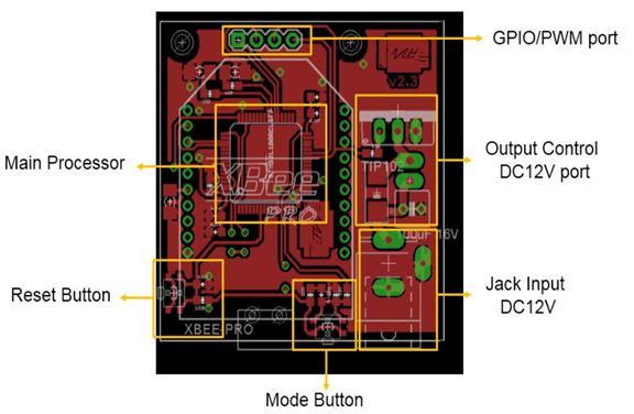
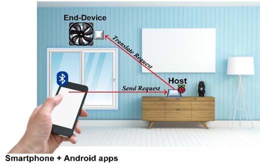
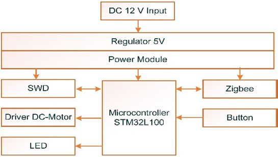
TEM Journal. Volume 10, Issue 3, Pages 1301‐1306, ISSN 2217‐8309, DOI: 10.18421/TEM103‐37, August 2021. Bluetooth [4], [5] on specified parameters. However, as for this version, ZigBee the pre-defined parameters (i.e., scheduling) and Radio Frequency [6] security measures are not yet implemented for the fan Wi-Fi control. This paper’s scope is limited to demonstrate SMS [7] the feasibility of controlling fan wirelessly through Voice [8] user’s smartphone, while security measures and Remote-less automated control [9] parameters such as scheduling will be defined and There is also an innovation of fan control implemented in future work. movement based on human motion [10] The system architecture for the fan control is depicted in Figure 2. In this work, the architecture is However, some of the existing works as mentioned divided into three parts: Android-based application as above have limited functionality in the form of the user interface, host/gateway to bridge the end-device standalone system. As such, this work aims to and the server, and end-node consisting several improve the functionality by design and blocks as depicted in Figure 3. The working principle implementation of remotely fan control on wireless of the system is elaborated further in accompanying sensor network (WSN) in the smart home system. It publications for this project [11], [12]. means that the fan device is connected with the others devices such as RGB lamp, humidity and temperature sensor, curtain, and smart plug in Mesh ZigBee network. (a) (b) Figure 2. The architecture of fan control Figure 1. (a) Exhaust fan (Documented by S. Fuada, 2016); (b) small DC fan as representation for exhaust fan In this work, the fan control system using on/off and PWM-based speed control is researched. The control for user will be conducted using smartphone- based application that provides slider-based or three buttons-based speed controls. The smartphone is not directly connected to the fan; instead, it is connected to a central host via Bluetooth, after which the host will process the command and send the result to the Figure 3. Hardware structure of Fan control system fan device through ZigBee network. As the scope of this work consists of prototype for In this work, the fan serves as one of the end-nodes smart home system, a small device is used as to be controlled through the host. The fan’s power is representation for the home appliance to be supplied using 12 VDC external adapter through DC controlled. Therefore, a small fan driven using DC jack interface. Some of the interface features offered motor is used as representation/model for exhaust fan consist of switch, reset and mode buttons, DC jack, commonly found on kitchen and bathroom wall. The output control port, and micro-USB port for firmware DC motor works at 12 VDC and 0.14 A. The update. For control purposes, STM32L100 representation of the device is depicted in Figure 1. microcontroller is used in this project due to its low power usage. 2. Methodology For the host, Raspberry Pi 2 is used as a “bridge” for the end-nodes, the central server, and user 2.1. System Description interface application. The Raspberry Pi 2 consists 4 USB connectors and USART GPIO. For connectivity Ideally, as part of a smart home system, the control with the end-nodes, the Raspberry Pi unit is and transmission of the commands for the fan should connected to a ZigBee module through the UART be secured and can be performed automatically based pin. The host works by processing commands from 1302 TEM Journal – Volume 10 / Number 3 / 2021.

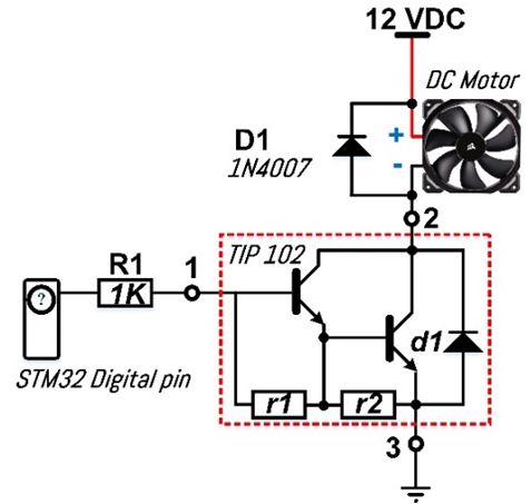
TEM Journal. Volume 10, Issue 3, Pages 1301‐1306, ISSN 2217‐8309, DOI: 10.18421/TEM103‐37, August 2021.

user’s smartphone received through Bluetooth, then
delivers the processing result to the end-nodes
through ZigBee. For the user interface, an Android-
based smartphone application is developed using MIT
App Inventor 2. Further details on the application
development are elaborated in previous work.

2.2. Hardware Design

 The structure of the hardware is elaborated in
Figure 3, while the schematic diagram is depicted in
Figure 4. In general, the hardware consists of a
power module and 5 VDC regulator, STM32L100
microcontroller, and an electronic driver. The
hardware operates by having the STM32L100
microcontroller to emit PWM signals through the Figure 4. Electronic driver for Fan control in switch
controller’s digital pin, which ranges from 0 to 3.3 topology, the detailed calculation refers to previous work
VDC. The speed of the fan is influenced by the PWM As safety measure for the transistor, a 1N4007
signals. diode is utilized as flyback diode. The purpose of the
 For the ‘on’ and ‘off’ switching of the fan, TIP 102 diode is to prevent damage from drastic current
BJT transistor with high-side configuration is increment when the transistor switches from “on”
employed as switch. The transistor has Darlington mode to “off” mode.
configuration, as such it has VBE = 1.4 VDC (obtained
from the summation of 0.7 VDC with 0.7 VDC) and 2.3. Software Design
power up to 80 Watt. When the voltage between VBE
 The flowchart for the fan control is depicted in
and ground is above 1.4 VDC, the transistor will enter
 Figure 5, while the flowchart for more specific
saturation region, causing the current from VCC to
 control from the user interface is depicted in Figure
ground to pass DC motor and transistor, and vice
 6. As this end-device is part of the designed smart
versa.
 home prototype, this work is related to other works
 Using the equation (1) for calculation, the base
 described in [5]. To support connectivity with the
current (IB) required to switch the TIP 102 into
 devices described in the aforementioned works,
saturation mode is identified to be 1.9 mA for RB = 1
 ZigBee protocol is used to connect the devices in
kΩ. As such, the RB value is used for switch
 mesh topology. The command for the end-devices is
operation of the transistor. Meanwhile, the power
 sent from Android-based application, whether using
dissipation of the transistor is calculated using
 hard control (fixed buttons such as for on/off
equation (2), resulting 0.28 watts power dissipation
 purposes) or soft control (using slider). Afterwards,
based on the values provided by the datasheet
 the host will process the command from the user
(IC=140 mA and VCE=2 VDC for saturation
 interface, then relay the result to the fan to be
condition).
 executed.
 (1)

 ∗ (2)

 Figure 5. Flowchart of fan control works, obtained from
 previous work

 TEM Journal – Volume 10 / Number 3 / 2021. 1303
TEM Journal. Volume 10, Issue 3, Pages 1301‐1306, ISSN 2217‐8309, DOI: 10.18421/TEM103‐37, August 2021.

 Figure 8. Bottom layer of the PCB design

Figure 6. Flowchart for Android application, reproduced
 from previous work

2.4. Protocol Design

 The communication protocol for this work utilizes
format proposed in previous works. As depicted in
Figure 7, the message consists of header (3 Bytes: 50,
4D, 45), device address (2 Bytes: 06, 3), packet
initialization (1 Byte: 80), data payload (1 Byte: 0 – Figure 9. Top layer of the PCB design
100%), and checksum, as well as each section’s
respective byte allocations.

 Figure 7. Packet data structure for Fan control, Figure 10. A photograph of implemented module
 reproduced from previous work

3. Results and Analysis

3.1. Implementations

 The printed circuit board (PCB) based on the
schematic diagram in Figure 3 is presented in Figure
8 and Figure 9. The PCB has 40.21 mm x 39.84 mm
dimension. Figure 10 shows the custom-built of DC
motor driver in which the implementation refers to
the Figure 4. While Figure 11 shows the Host that
 (a) (b)
employs Raspberry Pi and connected with Bluetooth
module, XBee, and WiFi module (for long-range Figure 11. (a) host module in compact box; (b) the
control/outdoor scenario). Table 2 shows the control anatomy of the host containing Xbee module, Raspberry
command for fan device in STM32 Microcontroller. Pi, Bluetooth module, and case

 1304 TEM Journal – Volume 10 / Number 3 / 2021.

TEM Journal. Volume 10, Issue 3, Pages 1301‐1306, ISSN 2217‐8309, DOI: 10.18421/TEM103‐37, August 2021.

Table 2. Control command for fan implementation testing result is elaborated in Table 3. After the
if(rawspeed==0) TIM3->CCR3=0; functional test is conducted, the power dissipation of
else { kec=(rawspeed/255)*500+500; the device is measured when the device is both idle
TIM3->CCR3=speed;} and in processing mode. The power dissipation is
 measured using power supply equipped with current
 and voltage displays. The result of the measurement is
 Humidity & Temperature depicted in Table 4.

 Fan
 1

 Door Lock
 3
 Curtain

 Power
 2
 Switch

 Figure 13. A setup for functional test of fan control
 including: (1) smartphone as a user interface; (2) host; (3)
 (a) end-device, which is fan

 Table 3. Results of Functional Test
 Commands
 Condition setting Results
 on GUI
 Fan rotates in 25% of its
 On (Speed I) √
 speed
 Fan rotates in 50% of its
 Speed II √
 speed
 Fan rotates in 75% of its
 Speed III √
 speed
 (b) Fan rotates in 100% of its
 Speed IV √
 Figure 12. Screenshot of developed android apps for fan speed
 control Off Fan is stopped √
 Depends on slider position
 As previously explained in Section II, the PWM Slider (rotates 0% to 100% of
 √
signal is generated by the STM32L100 speed)
microcontroller is used as reference for controlling Table 4. Power Measurement of Fan Device
the fan speed. The value is translated into byte value
ranging from 0 to 255 for data payload, with 0 Input Current
representing 0% PWM and 255 representing 100% voltage Idle condition Process condition
 12 VDC 43.1 mA 145.1 mA
PWM. The microcontroller’s TIM3 is used for the
timing, while the PWM configuration is described in
previous work. 4. Conclusion
 Figure 12(a) visualizes the Android application to
 In this work, a prototype of control system (with
control the fan for hard- and soft-control. The fan
 hard- and soft-control method) for electrical fan is
menu consists of four buttons and one slider as
 designed for smart home system. The system utilizes
depicted in Figure 12(b).
 STM32L100 microcontroller in order to support low-
 power operation. Based on the testing conducted, the
3.2. Testing
 fan can be configured for various speed, and it
 The functional testing is conducted to ensure the requires 43.1 mA (517.2 mW) in an idle condition
on/off and speed control to work as intended. The and 145.1 mA (1,741.1 mW) in a processing
testing process is depicted in Figure 13, while the condition.

 TEM Journal – Volume 10 / Number 3 / 2021. 1305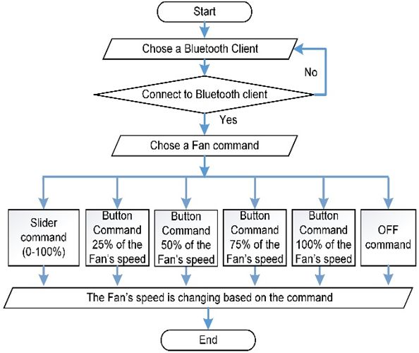
TEM Journal. Volume 10, Issue 3, Pages 1301‐1306, ISSN 2217‐8309, DOI: 10.18421/TEM103‐37, August 2021.

References [7]. Risanty, R. D., & Arianto, L. (2017). Rancang
 Bangun Sistem Pengendalian Listrik Ruangan Dengan
[1]. Khairudin, M., Yatmono, S., Nashir, I. M., Arifin, F., Menggunakan Atmega 328 Dan Sms Gateway
 & Aulia, W. (2021). Exhaust Fan Speed Controller Sebagai Media Informasi. JUST IT: Jurnal Sistem
 Using Fuzzy Logic Controller. In Journal of Physics: Informasi, Teknologi Informasi dan Komputer, 7(2),
 Conference Series (Vol. 1737, No. 1, p. 012046). IOP 45-54.
 Publishing. [8]. Prasatia, W., & Kamarudin, K. (2018). Kipas Angin
[2]. Dobbin, N. A., Sun, L., Wallace, L., Kulka, R., You, Pengikut Manusia Berdasarkan Wajah. Jurnal
 H., Shin, T., ... & Singer, B. C. (2018). The benefit of Integrasi, 10(2), 74-79.
 kitchen exhaust fan use after cooking-An https://doi.org/10.30871/ji.v10i2.906
 experimental assessment. Building and [9]. bt Aripin, N., & Othman, M. B. (2014, August).
 Environment, 135, 286-296. Voice control of home appliances using Android.
 https://doi.org/10.1016/j.buildenv.2018.02.039 In 2014 Electrical Power, Electronics,
[3]. Munir, M., & Erfianto, B. (2020, June). A Distributed Communicatons, Control and Informatics Seminar
 Fuzzy Logic with Consensus for Exhaust Fan (EECCIS) (pp. 142-146). IEEE.
 Controller. In 2020 8th International Conference on [10]. Langi, S. I., Wuwung, J. O., & Lumenta, A. S.
 Information and Communication Technology (2014). Kipas Angin Otomatis Dengan Menggunakan
 (ICoICT) (pp. 1-6). IEEE. Sensor Suhu. Jurnal Teknik Elektro dan
 Doi: 10.1109/ICoICT49345.2020.9166362 Komputer, 3(5), 41-48.
[4]. Purnamasari, I., & Rezasatria, M. (2019). Rancang [11]. Adiono, T., Putra, R. V. W., Fathany, M. Y., Lawu,
 Bangun Pengendali Kipas Angin Berbasis B. L., Afifah, K., Santriaji, M. H., & Fuada, S. (2016).
 Mikrokontroller Atmega 16 Melalui Aplikasi Android Rapid Prototyping Methodology of Lightweight
 Dengan Bluetooth. Simetris: Jurnal Teknik Mesin, Electronic Drivers for Smart Home
 Elektro Dan Ilmu Komputer, 10(1), 147-160. Appliances. International Journal of Electrical &
 https://doi.org/10.24176/simet.v10i1.2883 Computer Engineering (2088-8708), 6(5).
[5]. Ordila, R., & Irawan, Y. (2020). Penerapan Alat [12]. Adiono, T., Fathany, M. Y., Putra, R. V. W., Afifah,
 Kendali Kipas Angin Menggunakan Microcontroller K., Santriaji, M. H., Lawu, B. L., & Fuada, S. (2016,
 Arduino Mega 2560 Dan Sensor Dht22 Berbasis October). Live demonstration: MINDS—Meshed and
 Android. Riau Journal Of Computer Science, 6(2), internet networked devices system for smart home:
 101-106. Track selection: Embedded systems. In 2016 IEEE
[6]. Sunny, J., Thomas, K. A., Jyothish, P. M., Asia Pacific Conference on Circuits and Systems
 Jayaprakash, P. R., & Sindhu, S. (2017, April). (APCCAS) (pp. 736-737). IEEE.
 Design and implementation of RF controlled DOI: 10.1109/APCCAS.2016.7804031
 miniature fan. In 2017 International Conference on
 Circuit, Power and Computing Technologies
 (ICCPCT) (pp. 1-5). IEEE.

 1306 TEM Journal – Volume 10 / Number 3 / 2021.


You can also read