System Programming User Guide - INSTALL MAINTAIN - Lutron
←
→
Page content transcription
If your browser does not render page correctly, please read the page content below

P/N 041571j

System Programming User Guide
      For Hub Firmware Version: 1.14

                                       INSTALL

                                       MAINTAIN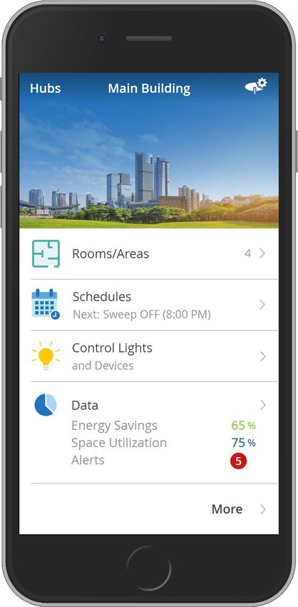
P/N 041571j

Table of Contents
What is a Vive system?......................................................................................................................................................4
      Components.........................................................................................................................................................................4
      Installation / Wiring................................................................................................................................................................4
Lutron Vive App.....................................................................................................................................................................5
Initial Configuration............................................................................................................................................................6
      Connect to the Hub (via browser)........................................................................................................................................6
      Set Up Wi-Fi Connection (via browser)...............................................................................................................................6
Create a Password for the Hub......................................................................................................................................8
Commissioning.....................................................................................................................................................................9
      Create an Area......................................................................................................................................................................9
      Add Devices........................................................................................................................................................................10
         Add a Pico Remote Control and Assign Devices.................................................................................................................10
         Add a Sensor and Assign Devices.....................................................................................................................................14
         Add Devices Directly to the Hub........................................................................................................................................16
Find Devices not Showing up in Discovery.............................................................................................................18
      Device Too Far Away..........................................................................................................................................................18
      Unsupported Device..........................................................................................................................................................18
      Devices Set Up Without the Hub.......................................................................................................................................18
Rename Devices.................................................................................................................................................................19
Troubleshoot Devices.......................................................................................................................................................19
Programming.......................................................................................................................................................................20
      Occupancy / Vacancy Sensor Settings..............................................................................................................................20
         Status.............................................................................................................................................................................20
              Sensitivity...................................................................................................................................................................20
              Timeout......................................................................................................................................................................20
         Occupancy Settings / Programming...................................................................................................................................20
              Occupancy / Vacancy Behavior.........................................................................................................................................20
              Occupied / Unoccupied Levels..........................................................................................................................................21
         All Occupancy Sensors Work Together..............................................................................................................................22
         Occupancy Grouping....................................................................................................................................................................... 23
         Control Receptacles / CCO Modules Using Occupancy Grouping................................................................................................. 23
         Occupancy Dependency.................................................................................................................................................................. 25
Tuning......................................................................................................................................................................................26
      High-end / Low-end Trim....................................................................................................................................................26
Minimum Light Level.........................................................................................................................................................27
Maximum Light Level.......................................................................................................................................................28
Daylighting............................................................................................................................................................................29
      Best Practices....................................................................................................................................................................29
      Individual Fixture Sensors.................................................................................................................................................29
      Radio Powr Savr Daylight Sensors....................................................................................................................................30
          Multi-row Daylighting.......................................................................................................................................................30
Schedules..............................................................................................................................................................................32
      Create Schedule.................................................................................................................................................................32
      Modify and Test Schedules...............................................................................................................................................36
Continued on next page...

                                                                                                 2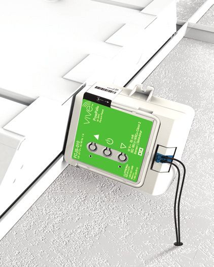
P/N 041571j

Table of Contents (continued)
Alerts.......................................................................................................................................................................................37
Load Shed.............................................................................................................................................................................38
OpenADR...............................................................................................................................................................................40
Emergency............................................................................................................................................................................43
Cloud Backup......................................................................................................................................................................43
BACnet....................................................................................................................................................................................44
      Settings...............................................................................................................................................................................44
API Integrations..................................................................................................................................................................47
      Instructions to Integrate.....................................................................................................................................................47
Scenes....................................................................................................................................................................................49
      Create a Scene...................................................................................................................................................................49
Control and Monitor..........................................................................................................................................................52
Runtime Status...................................................................................................................................................................55
      Fixture Sensor Gets Connected........................................................................................................................................55
Configure the Hub.............................................................................................................................................................57
      Firmware Update................................................................................................................................................................57
      Ethernet Settings................................................................................................................................................................58
      Wi-Fi Settings.....................................................................................................................................................................59
      Time & Date / Location........................................................................................................................................................60
      Accessing Other Hubs on the Wired Network..................................................................................................................60
      Hub Support File.................................................................................................................................................................61
      Reset Passwords and Settings..........................................................................................................................................62
Security Log.........................................................................................................................................................................63
Security Certificates.........................................................................................................................................................64
Vive Vue..................................................................................................................................................................................65
Lutron Contact Numbers................................................................................................................................................66

                                                                                              3
P/N 041571j

 What is a Vive system?
 The Lutron Vive system is a simple and scalable wireless lighting control solution for new and existing commercial buildings.
 Some of the many benefits of a Vive system are:
• Flexibility needed to design a building
• Wireless technology simplifies installation and reduces callbacks
• Maximize productivity and building performance
• Dependability and confidence that the system will work from the start and will keep working
• Visible and traceable energy savings control and monitoring

 Components
                                                                                                                             Emergency
 Lutron Vive app         Vive wireless hub                        Ceiling mount            Fixture mount                     PowPak controller

                                                                  PowPak controller        PowPak wireless
                                                                  with J-box               fixture controller with
                                                                                           fixture sensor

 Radio Powr Savr                               Wallbox mount                                                                 PowPak
 occupancy / vacancy sensor                                                                                                  fixture sensor

                                               Maestro Wireless               Maestro Wireless dimmer/
                                               dimmer / switch                switch with sensor

  Radio Powr Savr                Pico remote                 Integral fixture control                       Wireless receptacle   Dimming module
  daylight sensor                control

 Installation / Wiring
 For directions on how to install Vive devices, refer to the installation instructions included with the product. This guide is based on
 the premise that all devices are already properly installed and wired.

                                                                          4
Install
                                                                                      P/N 041571j

  Lutron Vive App
  The Lutron Vive app is available for download on iOSR and AndroidT
  devices. The app is compatible with Vive hub software version 1.5
  and newer. Older versions of hub software must be upgraded before
  using the Vive app.

1. D
    ownload the app from the App Store or the Google PlayT store.

2. L
    aunch the app and follow the instructions to create a myLutron
   account. If you already have a myLutron account, enter the account
   credentials into the app.

3. V
    erify your email address and login to your account.

4. Create a project in the app and add Vive hubs to the project. The
   app provides a consolidated view of all projects and every hub
   within a project. The app allows an installer to activate the extended
   warranty and “hand off” a project to the customer.

  When a project is handed off to the customer, an e-mail that
  contains the project details will be sent to the customer. The
  customer will be able to access the project, view the hubs, and see
  other details related to the project.

                                                                    5
Install
                                                                                       P/N 041571j

  Initial Configuration
  The Vive software is used to program the Vive wireless hub (known
  as “hub” hereafter). A hub can be accessed via Lutron Vive app
  or a web browser (Google ChromeT browser or Safari application
  program recommended).

  If the Vive app is used, follow the instructions in the app to create a
  project and add hubs to it. Multiple users can be invited to a project
  and can access and collaborate on a project from different devices.

  Note: The hub can be programmed by connecting a smart device
  (e.g., phone, tablet, or laptop) to the built-in Wi-FiR chip of the hub.
  There is no requirement to connect to external or building Wi-Fi
  networks.

  Connect to the Hub (via browser)
1. E
    nable the Wi-Fi connection on the smart device.

2. N
    avigate to the list of available networks. When in range of the hub,
   you should see a network name similar to “Vive-017d20b9”. The text
   that follows “Vive” in the network name is the serial number of the
   hub. Connect to this network.

  Set Up Wi-Fi Connection (via browser)
1. O
    pen a web browser and type “vive.lutron.com” into the address
   bar. An image of the hub will appear and the antenna on the hub
   that you are connected to will flash white. If this is not the correct
   hub, return to the list of Wi-Fi networks and choose a different
   network. Once you have found the correct hub, tap “Yes, setup this
   hub”.

  Note: If you want to set up the hub via the app, follow instructions in
  the app to set up a project and add hubs.

2. Tap the current name of the hub and rename it (e.g., Vive_floorOne).
    This will be the Wi-Fi network name of this hub. A good descriptive
    name will help you and others identify this hub later.

3. T
    ap “Next”.

  Continued on next page...

                                                                       6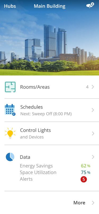
Install
                                                                                       P/N 041571j

  Initial Configuration (continued)
4. Type in a secure password for the Wi-Fi network and tap “Done”.

  A strong password is required to keep the account secure.

  A password must:
  a. be at “Medium” strength or higher.
  b. contain at least 8 characters.
  c. NOT contain these characters: ‘x’    “x”
  Follow the guidelines below to create a secure password.
  • Increase the length of the password.
  • Include both uppercase and lowercase letters.
  •A
    dd numbers or special characters.

  Note: Tap “Show” or “Hide” to view or hide the password you are
  typing.

5. Record the password in a secure location.

6. T
    he hub will apply these settings and will disconnect from the
   smart device. Go back to the Wi-Fi settings screen on the smart
   device and connect to the hub network using the Wi-Fi name and
   password you just created.

7. R
    eturn to the web browser and tap “Vive”. You will be presented with
   a short tutorial on the Vive software. After reviewing the screens, tap
   “Get Started”.

8. Y
    ou will be directed to the main dashboard of the Vive software.
   You can start creating the system by following the steps in the
   Commissioning section of this guide.

                                                                    7
Install
                                                                                 P/N 041571j

  Create a Password for the Hub
  Optional: Lutron recommends creating an additional password
  for the hub. This increases security and is required to access the
  application over a wired network.

1. F
    rom the main dashboard in the Vive software, tap “   ” and then
   tap “Set Hub Sign In Password”.

2. E
    nter a secure password for the hub and tap “Save”.

  A strong password is required to keep the account secure.

  A password must:
  a. be at “Medium” strength or higher.
  b. contain at least 8 characters.
  c. NOT contain these characters: ‘x’    “x”
  Follow the guidelines below to create a secure password.
  • Increase the length of the password.
  • Include both uppercase and lowercase letters.
  •A
    dd numbers or special characters.

  Note: Tap “Show” or “Hide” to view or hide the password you are
  typing.

3. R
    ecord the password in a secure location.

                                                                   8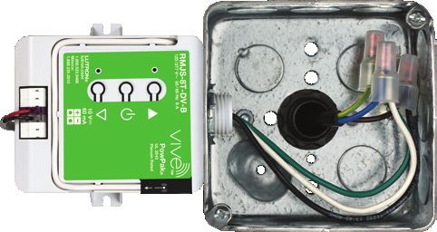
Install
                                                                                   P/N 041571j

  Commissioning
  The Vive system uses wireless signal strength measurements to
  make adding fixtures to an area as quick and efficient as possible.
  To take advantage of this technology, ensure that you are physically
  in the room to be programed when performing these steps.

  Create an Area
  An area is a room or space in the building (e.g., conference room,
  office, or hallway).

1. F
    rom the main dashboard in the Vive software,
   tap “Rooms/Areas”.

2. S
    elect “Add a room or area” and name the area.

  Continued on next page...

                                                                  9
Install
                                                                                      P/N 041571j

  Commissioning (continued)
  Add Devices
  Add a Pico Remote Control and Assign Devices
1. S
    elect “Pico” as the type of device you want to add.

  Note: You may choose to start with any device. You can even start
  with a device that is not shown by selecting “I don’t have any of
  these devices in my area”. The following steps are based on using a
  Pico remote control.

2. P
    ress and hold the bottom button on a Pico remote control for
   10 seconds until the screen says “Adding device”.

  Note: You do not need to select the correct Pico remote control
  model number before pressing the button. When you press the
  button, the software will automatically recognize what model you are
  using. The images in the software are a guide and may not illustrate
  the exact model you are using.

3. T
    ap “Continue” on the “Finding Lights / Devices” illustration. This
   illustration will appear when adding the first device.

  The software will find lights / devices nearby. You will be presented
  with a list of devices that is ordered based on the strength of the
  wireless signal. The devices closest to the Pico remote control will
  appear at the top of the list. The serial number is the default name
  for that device. The name can be changed later.

  Note: Any lights / devices manually assigned (button press method)
  to this Pico remote control will appear in the list as “Not added to
  hub” and will need to be added. If the lights / devices are controlled
  by any other controlling device (e.g., sensors), then they will need to
  be reassigned to those devices via the hub .  vacancyva

  Note: The “Continue searching...” button can be used to reveal more
  loads that may be farther away from the Pico remote control. Tap
  this button if the devices do not appear in the list.

  Note: In very large rooms (e.g., open office) you may need to move
  around the space and tap “Start new search” several times to
  capture all of the devices.

  Continued on next page...

                                                                      10
Install
P/N 041571j
Commissioning (continued)
Add Devices (continued)
Add a Pico Remote Control and Assign Devices
(continued)
4. Tap “FLASH” and the load will flash to identify the device. If this is
the desired device, tap “+”. Repeat this step for each device that you
want to add to the area.
Note: PowPak receptacle controllers and CCO controllers will not
cycle on and off when you tap “FLASH”. Instead, these devices will
rapidly flash the LEDs on the front of the PowPak controller.
Note: If you are adding a 4-button 2-group Pico, you can add lights/
devices to one or both groups. These lights/devices will be then be
controlled by the Pico group button presses.
5. Press “Add Tag” to tag a device, light, or control for future reference.
When adding controlling devices, these tags will be displayed and
the devices will not need to be flashed again for identification.
Tags are flexible and can be used in any way desired. They can be
used to name new areas. Examples of tags are “Sales Area”, “Front
Row”, and “Conference Room”.
6. A
Pico remote control can control devices in multiple areas. To
add a device from another area, tap “Show lights / devices in other
rooms / areas...”. Select the desired area and tap “+”.
Note: The Pico wireless control must be located within 30 ft (9 m)
through walls or 60 ft (18 m) line-of-sight of all devices that it
is controlling.
Continued on next page...
11Install
P/N 041571j
Commissioning (continued)
Add Devices (continued)
Add a Pico Remote Control and Assign Devices
(continued)
7. F
or each device added, enter the total wattage of the load(s) in the
appropriate “Wattage (W)” field. This is required to obtain the most
accurate energy reporting via the Vive software or BACnet.
Note: The Vive software will automatically report energy usage
for fixtures with a PowPak fixture controller. Vive Integral Fixture
Controls may also report energy usage automatically. Check the
Vive Integral Fixture Control product specification for more details.
Note: The wattage for PowPak receptacle controllers cannot be
entered since the wattage can change over time based on what is
plugged into the receptacle.
Note: The energy savings reported is instantaneous only. If
historical energy reporting is needed, a premium hub with BACnet
should be configured to work with a BMS. The BMS will store and
report historical energy savings data.
Note: In the case that Vive Integral Fixture Controls were added, it
is possible to a enter common wattage for each device. It is also
possible to enter the wattage of each device individually by tapping
“Set different wattage for each light.”
8. T
ap “Next” and rename the Pico remote control.
9. If using a 3BRL Pico remote control, tap “Favorite button
programming” to reprogram the favorite button to the desired level.
You can set all of the loads to the same level or individual levels.
The “Preview” button allows you to see the programming live
without making any changes.
Note: On 2B, 2BRL, 3B, and 3BRL Pico remote controls, the top
and bottom buttons will turn all assigned loads to 100% and 0%
respectively. On a 4B Pico remote control, the bottom button turns
all assigned loads to 0%. The middle button on a 3B and 3BRL
and the top three buttons on a 4B can all be programed to desired
preset levels.
Note: The PowPak CCO controller (RMJS-CCO1-24-B) can be
programmed like other relay devices (open / close). For PowPak
controllers that have both line voltage relays and contact closure
outputs (CCOs), the CCO will always mimic the relay and can not
be programmed separately.
Continued on next page...
12Install
P/N 041571j
Commissioning (continued)
Add Devices (continued)
Add a Pico Remote Control and Assign Devices
(continued)
10. To set the fade duration for the Pico remote control, tap “Fade”.
This time specifies the length of the transition between the original
and target light levels of the dimmable lights assigned to the Pico
remote control.
11. E
xtend the wireless range of a Pico wireless control if it is
controlling devices in multiple rooms or lights / devices beyond the
normal range. This ensures that far away lights / devices responds
to the Pico wireless control.
Note: This feature extends the wireless range of a Pico wireless
control to the full range of the hub that it is assigned to. It cannot be
used to control devices beyond the range of the hub.
Note: A hub will automatically extend the range of Pico wireless
controls if they fall under a recommended category; however, you
may choose to disable the range extension feature.
Note: A maximum of 15 Pico wireless controls can have their range
extended.
12. In a new room, if you have added multiple fixtures with sensors
to the Pico control, or a wireless daylight sensor, then you will be
given the option to enable all occupancy sensors to work together.
When working together, if any of the sensors detect occupancy,
then all lights associated with all of the sensors will turn on.
The option can be changed by tapping on the room, where
occupancy settings may be changed.
Continued on next page...
13Install
P/N 041571j
Commissioning (continued)
Add Devices (continued)
Add a Sensor and Assign Devices
1. F
rom the “Add device” screen, select the desired sensor type.
or
2. In a room with an existing wireless occupancy sensor, if you add an
additional wireless sensor, then you will be given the option to enable
all occupancy sensors to work together. When working together, if
any of the sensors detect occupancy, then all lights associated with
all the sensors will turn on.
he option can be changed by tapping on the room, where
T
occupancy settings may be changed.
3. P
ress and hold the indicated button on the sensor for 10 seconds.
The system will perform another wireless signal measurement like it
did with the Pico remote control in the previous section. or
Continued on next page...
14Install
P/N 041571j
Commissioning (continued)
Add Devices (continued)
Add a Sensor and Assign Devices (continued)
4. Once the list appears, tap “FLASH” to identify the load and tap “+”
to add it.
Any loads already programmed to a Pico remote control are labeled
as such. This allows you to quickly identify which devices are
already part of the area.
Note: For wireless daylight sensors, the lights can be added
to different rows. There can be a different target brightness for
different rows of lights.
Note: For safety reasons, PowPak receptacle controllers and
PowPak CCO controllers will not flash their relay output when you
tap “FLASH”. Instead, these devices will rapidly flash the LEDs on
the front of the PowPak controller.
Note: PowPak receptacle controllers cannot be assigned to a
daylight sensor.
Note: If there are many devices in the area, it may be easier to
rename them first before adding additional sensors. This allows the
fixtures to be identified easier when assigning them to sensors.
5. Enter the total wattage of each load in the appropriate “Wattage
(W)” field for each device. This is required to get accurate energy
data.
Note: In the case that Vive Integral Fixture Controls were added
that do not automatically report energy usage, it is possible to enter
a common wattage for them. It is also possible to enter the wattage
of each device individually by tapping “Set different wattages for
each light.”
6. T
ap “Next” and rename the sensor. Tap “Done.”
15Install
P/N 041571j
Commissioning (continued)
Add Devices (continued)
Add Devices Directly to the Hub
1. T
ap “Add Device” at the room’s device screen.
2. T
ap “I don’t have any of these devices in my room / area” and then
select the desired device.
3. P
ress and hold the indicated button for 10 seconds. The screen will
show which button to press.
Continued on next page...
16Install
P/N 041571j
Commissioning (continued)
Add Devices (continued)
Add Devices Directly to the Hub (continued)
Note: While adding an In-Wall Dimmer/Switch with sensor in the
room, additional lights/devices can be assigned to the sensor. The
occupancy of lights/devices added to the sensor will be controlled
by the sensor; however, the dimmer/switch will not control these
additional lights. It will only control its wired lights.
4. Rename the device and enter the total wattage of each load in the
appropriate “Total Wattage (W)” field for each device. This is required
to get accurate energy data.
Note: The Vive software will automatically report energy usage
for fixtures with a PowPak fixture controller. Nothing needs to be
entered for these fixtures. If power for the fixture is not wired
through the PowPak fixture controller, the software will report 0 W
for that fixture.
Note: If additional devices are added to the sensor of an In-Wall
Dimmer/Switch with sensor, then an additional section with that
information will display on the device detail screen.
5. Tap “Done”.
17Install
P/N 041571j
Find Devices not Showing up in
Discovery
Device Too Far Away
Sometimes a device cannot be found during the “Finding
Lights / Devices” step. Follow the steps below if you are having
difficulty finding a device that you would like to add to an area via a
Pico remote control or sensor.
1. O
n the “Select Lights” screen, tap “Start new search”.
2. M
ove a Pico remote control or sensor close to the device that you
are trying to add.
Note: Devices can be wired to multiple loads in an area. Move the
Pico remote control or sensor near the device, not the load.
Note: The Pico wireless control must be located within 30 ft (9 m)
through walls or 60 ft (18 m) line-of-sight of all devices that it
is controlling.
3. P
ress and hold the indicated button on the Pico remote control or
sensor for 10 seconds. The system will perform a wireless signal or
measurement and the device should be listed.
If you still cannot find the device, check the following:
• Verify that the device has power.
• Ensure that the device is properly wired.
• Sometimes large metal objects can decrease the signal strength of
a device making it appear further away. Move to the other side of
the room as that may make the device appear closer.
Unsupported Device
If the hub software does not support a specific device, you will get
an “Unsupported device” error message when trying to add that
device. Follow the steps in the Firmware Update section to update
the hub software. Once the hub software has been updated, add
the device to the hub.
Devices Set Up Without the Hub
If a light / device was manually assigned (button press method) to a
different device (e.g., Pico remote control, sensor), the light / device
will be shown in the discovered list but cannot be added until it
is restored to factory defaults. To do this, follow the steps on the
screen or in the installation instructions (provided with the device).
18Install
P/N 041571j
Rename Devices
1. T
ap “Rooms & Areas”, and select the area that contains the device.
2. F
or lighting controls, expand “Lights” and select the desired device.
For PowPak receptacle controllers and CCO controllers, expand
“Receptacles and CCO Modules” and select the desired device.
3. R
ename the device and tap outside of the “Name” field to save the
changes. A “Saved” confirmation note will be displayed.
Troubleshoot Devices
If a light / device is not behaving as expected, then try the
troubleshooting steps mentioned at the device detail screen.
Follow the steps below to navigate to the device detail screen:
1. T
ap “Rooms/Areas”, select the area that contains the device.
2. E
xpand “Lights” and select the desired device.
3. T
ap “Troubleshoot” to open screen with troubleshoot instructions.
4. Follow the instructions.
19Install
P/N 041571j
Programming
Occupancy / Vacancy Sensor Settings
1. N
avigate to the area that contains the sensor to be adjusted. Go to
“Occupancy” section of the screen and tap “...” and select “Sensor
Settings”.
In this menu, there are multiple settings that can be changed. See
below for details about these settings.
Status
se the slider to enable or disable the occupancy / vacancy sensors
U
in that area.
Sensitivity
ap “Sensitivity” to adjust the sensitivity of the occupancy / vacancy
T
sensors. These settings will only appear if there is a PowPak fixture
controller with a fixture sensor in the area. Sensitivity for a Radio
Powr Savr sensor must be set locally on the sensor. Instructions on
how to do this will be shown on the software screen.
Note: Sensitivity should be increased if the sensors are not detecting
motion (e.g., lights turn off when people are in the room). Sensitivity
should be decreased if the sensors are detecting too much motion
(e.g., lights do not turn off after the timeout period).
Timeout
ap “Timeout” to change the occupancy timeout for fixture sensors.
T
These settings will only appear if there is a PowPak fixture controller
with a fixture sensor in the area. Radio Powr Savr sensor timeouts
must be changed locally on the sensor. Instructions on how to do
this will be shown on the software screen.
2. O
nce the desired settings are changed, tap “Save” on the
respective screen.
Continued on next page...
20Install
P/N 041571j
Programming (continued)
Occupancy / Vacancy Sensor Settings
(continued)
Occupancy Settings / Programming
• Navigate to the area that contains the sensor to be adjusted. Go to
“Occupancy” and select “Programming”.
• Refer to “Lights & CCO Modules” to adjust occupancy / vacancy
behavior, occupied / unoccupied levels, and other settings for lights
and CCO modules.
• Refer to “Receptacles” to view occupancy / vacancy behavior and
occupied / unoccupied settings for receptacles.
Note: The occupancy settings for a device type will only
display if there are corresponding devices being controlled
by an occupancy / vacancy sensor in that area. For example,
“Receptacles” will only be displayed if receptacles are being
controlled by an occupancy / vacancy sensor in that area.
Occupancy / Vacancy Behavior
et the “Occ / Vac” or “Vac Only” behavior in the area as desired.
S
This can be set the same for all the lights / devices in the area or it
can be set individually for each light / device.
• Occ / Vac = auto on; auto off
• Vac Only = manual on; auto off
Note: The RMJS-20R PowPak receptacle controller cannot be set
to “Vac Only”. It will always operate as “Occ / Vac” and the occupied
and unoccupied settings will always be “On” and “Off” respectively.
Note: The only two methods to enable / disable occupancy in a Vive
system are through this screen and via BACnet protocol.
Occupied / Unoccupied Levels
djust the occupied and unoccupied levels as desired for the
A
dimmable lights in the area. This can be same level for all dimmable
lights in the area or different levels for each dimmable light.
Note: Switched lights will always be set as “On” when occupied and
“Off” when unoccupied. CCOs will always be set as “Closed” when
occupied and “Open” when unoccupied.
Continued on next page...
21Install
P/N 041571j
Programming (continued)
Occupancy / Vacancy Sensor Settings
(continued)
All Occupancy Sensors Work Together
E
nable this setting for the room if you want all occupancy-controlled
lights/devices to turn on and off together when any occupancy
sensor in the room detects a change. Occupancy sensors added
later will also automatically control these lights/devices.
T
ap “Set sensors to work together” and then “All sensors work
together” to enable this setting.
In large or oddly shaped rooms, such as long hallways and open
offices, lights/devices may be outside the range of the occupancy
sensors. You can extend the wireless range so that all occupancy
sensors in the room can control any light/device in that room,
regardless of distance between these sensors and the device. You
can extend the wireless range of occupancy sensors for up to 14
rooms per Vive hub. Tap “Yes” on the Wireless Range screen to
enable this setting and select the room type.
22Install
P/N 041571j
Programming (continued)
Occupancy / Vacancy Sensor Settings
(continued) Group 1
Occupancy Grouping
Below are two main applications of occupancy grouping with
fixture sensors.
Note: Occupancy grouping is not used with Radio Powr Savr
occupancy / vacancy sensors because devices are assigned to the
sensors directly. Also, devices can be assigned to more than one
sensor at a time for rooms with multiple sensors.
• Group fixture sensors together to form larger occupancy groups Group 2
(e.g., open office). When fixture sensors are grouped, all the lights
will turn on and off together. If one sensor sees movement, all the
lights will turn on. Conversely, all the sensors in the group must be in
the unoccupied state before the lights turn off.
• Allow control of devices other than fixture controls via fixture sensor
(e.g., private office where a fixture sensor controls both the fixture
and the PowPak receptacle controller).
To the right is an example of occupancy grouping. The four fixtures
are grouped into two separate occupancy groups based on the
furniture layout. Each group operates independently with the
corresponding fixture sensors and all four fixtures are part of the
same area.
Control Receptacles / CCO Modules Using
Occupancy Grouping
Note: If the fixture occupancy sensors are set to work together,
then they will all work as one occupancy group in the room.
In this case, expand the Occupancy section to find the “Control
Receptacles / CCO Modules” to open a screen to add devices (like
receptacles) to the occupancy group. Tap “Show fixture sensors” to
list fixture sensors which are working together in the room.
Note: “Control Receptacles / CCO Modules” link on the screen will
not display if a few devices without sensors (receptacles, CCO
Modules ) are already being controlled by fixture sensors. Instead,
the “Devices without sensors” row will display in place of it.
23Install
P/N 041571j
Programming (continued)
Occupancy / Vacancy Sensor Settings
(continued)
Control Receptacles / CCO Modules Using
Occupancy Grouping (continued)
Follow the steps below to create multiple different occupancy groups
using fixture sensors.
1. To create multiple occupancy groups using one or more fixture
sensors, first set sensors to work separately and then select “Control
receptacles using occupancy” if receptacles or CCO modules are
required to be grouped or “Create a group of lights” if only lights need
to be grouped with the fixture sensors.
2. T
o create an individual fixture sensor’s occupancy group when there
are wireless occupancy sensors working together in the room, first
set the sensors to work separately. If you want other devices to be
controlled by occupancy, then add them to any occupancy sensor.
3. F
ollow the steps to select devices and fixture sensors to group. Now
all the fixture sensors in the group will work together to control the
grouped devices.
Note: In order to create an occupancy group, at least two
lights / devices and at least one fixture sensor must be added.
24Install
P/N 041571j
Programming (continued)
Occupancy / Vacancy Sensor Settings
(continued)
Occupancy Dependency
When adding an occupancy sensor to a room / area, you select which
devices that sensor will control. You can also select devices in other
room / areas to be controlled by that same sensor. These devices will
now become dependent on the occupancy status of this sensor. For
example, users working in private offices may want the lights to stay
ON in an adjacent hallway.
When an occupancy sensor in one room controls lights in another
room, each room still has its own occupancy programming
(occupied / unoccupied levels, occ-vac / vac-only) and sensor settings
(enable/disable, sensitivity, timeout). For instance, if a sensor in one
room is programmed to affect lights in a second room, the sensor will
have no effect on the second room if Occupancy is disabled in the
second room.
Follow these steps while adding an Occupancy sensor to a room, to
make that sensor control lights in another room:
1. On the Select Devices screen, tap “Control other rooms/areas”.
Note: The “Control other rooms/area” option will be presented only
if other rooms already exist. If you add another room later, you can
come back to this screen and add it to this sensor.
2. Expand the room you wish to control and tap “+”.
Note: Depending on room configuration, your experience may vary.
3. If sensors are not already set to work together, you will be asked
whether to proceed, in which case you should tap “Set sensors to
work together”.
Note: Once occupancy sensors are set to work together, if any
sensor in that room detects motion, then all lights associated with
those sensors will turn on.
4. If occupancy range is not already extended in the room, you will be
asked how to proceed. Tap “Continue with range extension”, or make
sure that all lights in the room are within 98.5 ft (30 m) range before
tapping “Continue without range extension”.
Note: You may not use a sensor in one room to control lights in
a second room if that second room includes fixtures with wired
sensors or integral fixture controls (and they are enabled).
Note: You can make this sensor control more rooms later by editing
which devices are affected by this occupancy sensor.
Note: You can go to a room Occupancy section to see all sensors
(including from other rooms) which control that room.
25Install
P/N 041571j
Tuning
High-end / Low-end Trim
1. T
ap “Rooms & Areas” and select the desired area.
2. Expand “Lights”.
3. T
ap “Low-End trim” to adjust the low-end trim of the device. The
device will not go below this level. This can be set the same for all
devices or each device individually.
Note: Low-end trim is different than the minimum light level.
Low-end trim is the lowest level the load will dim down to before
turning off. The minimum light level is the level the load goes to
when commanded to turn off.
26Install
P/N 041571j
Minimum Light Level
This setting should be used if you want the load to go to a specific
level when “turned off” but never actually turn off. This is primarily
used in paths of egress (e.g., corridors and hallways).
1. T
ap “Rooms & Areas”, and select the desired area.
2. Expand “Lights” and select the desired device.
3. T
ap “This light should not turn off” and select the minimum light level
that the load should not dim below. Tap “Save”.
Note: The minimum light level is different than low-end trim. The
minimum light level is the level the load goes to when commanded
to turn off. Low-end trim is the lowest level the load will go before
turning off.
27Install
P/N 041571j
Maximum Light Level
From the Vive software, you can set the maximum light levels for
lights, which will cap light levels to reduce brightness in the space
and save energy. The devices will not go above this maximum level.
Follow the below steps to set maximum light levels.
1. T
ap the “More” menu on the main dashboard of the Vive software.
2. Tap “Maximum Light level” to set the levels.
3. S
et the maximum light levels for all dimmable lights. To set devices
to different levels by area, tap “Set per room / area”.
4. To set devices to different maximum levels by device in an area, tap
“Set per light” in that area.
28Install
P/N 041571j
Daylighting
Daylight harvesting reduces the use of artificial lighting when daylight
is available in order to reduce energy consumption. This applies to
all operations, including all Pico button presses. Daylight calibration
is either done automatically (fixture sensor) or manually through or
button presses (Radio Powr Savr daylight sensor). Details on
daylight sensor calibration are covered below.
Best Practices
1. Calibrate space first for best results.
• P
erform calibration when the space is receiving adequate, indirect
sunlight. Do not calibrate when there is direct sunlight entering the
space or when there is low sunlight.
• P
erform calibration after all of the furniture or equipment has been
moved into the space and after all painting has been completed.
• If a customer has specific requirements for illumination,
measurements using a light meter may be required to adjust the
light levels to match these requirements. After noting the required
level, take lux measurements with a light meter at work surface
height [typically 91.4 cm (3 ft) above finished floor] and directly
under the row of fixtures being tuned.
2. If the brightness still does not meet expectations after calibration,
set the target brightness level to fine tune the light level in the
space.
Individual Fixture Sensors
• Fixture sensors will automatically perform daylight calibration the first
time the sensor goes to the unoccupied state. The fixture sensor is
both an occupancy and daylight sensor.
• A fixture sensor will only control the PowPak fixture controller that
it is attached to. Daylight information cannot be shared from one
individual fixture sensor to other devices.
• If a Radio Powr Savr daylight sensor is assigned to a PowPak
fixture controller, the daylight sensor function of the fixture sensor
will be disabled.
Continued on next page...
29Install
P/N 041571j
Daylighting (continued)
Radio Powr Savr Daylight Sensors
Radio Powr Savr daylight sensors must be calibrated manually.
Refer to these sections of the Radio Powr Savr daylight sensor
installation instructions: Calibration, Testing the Daylight Sensor, and
Tuning the System.
Note: You do not need to press a button on PowPak devices
because they will automatically enter calibration mode.
Instead of pressing and holding the “Cal” button on the sensor, you
can shine a green laser (available at hardware or office supply stores)
on the sensor two times to put it in calibration mode. This is the
same procedure used for association.
! WARNING! Eye Injury and/or Blindness Hazard. May
Result in Serious Injury or Death. Avoid direct eye
exposure to laser beam.
• Use of laser pointer is NOT recommended for use with Lutron
products located near reflective surfaces.
• Do NOT aim or shine laser pointers at any person, pet, vehicle,
or aircraft directly, or through reflection by mirrors or other shiny
surfaces. Do NOT view the laser beam through binoculars,
magnifying glass, or other optical devices.
• Do NOT allow children to use laser pointers.
• Read and follow the laser pointer manufacturer’s instructions
on safe use. In the event of injury, get medical attention immediately.
Multi-row Daylighting
To the right is an example of multi-row daylighting using a Radio Powr
Savr sensor. To complete a similar setup, follow the steps below.
Row 1 Row 2
1. In the Vive software, assign all fixtures to the daylight sensor.
2. M
anually adjust the devices for all rows to achieve the desired
foot-candle (fc) level.
Note: It may be a challenge to physically find where the PowPak
devices are located and manually adjust them to reach the desired
Window
foot-candle level. To alleviate this challenge, you can assign a
2BRL Pico remote control to each PowPak device participating in
daylighting so that you can adjust the level remotely. After daylighting
has been calibrated, you can remove the 2BRL Pico remote controls
from the Vive system database.
Continued on next page...
30Install
P/N 041571j
Daylighting (continued)
Multi-row Daylighting (continued)
3. T
o adjust the daylighting settings, navigate to the area dashboard
that contains the daylight sensor. Expand “Daylighting” section and
select “Settings”.
4. Tap the daylight sensor to be calibrated and read “Getting started”.
Tap “Next” and follow the instructions to perform calibration.
Note: Check out “Best Practices” in the beginning of
this section for tips on calibrating the sensors.
5. If brightness still not does meet expectations after calibration, tap
“Target Brightness” to adjust the target brightness of the room.
These changes are live so that you can view the changes and fine
tune until your space is at your desired level. If the daylight in the
space is at a high level during adjustment, changes may not be
perceivable. You can adjust and save target brightness of all lights or
lights connected to a specific sensor.
ote: This option only displays if a wireless daylight
N
sensor has been added to the room.
6. Use the slider to Enable or Disable daylighting in that area.
7. T
ap “Allow daylighting to turn off dimmable lights” to allow or
prevent dimmable lights to turn off due to daylighting. If “Yes” is
selected, the lights may turn off if enough daylighting is present
in the room. If “No” is selected, daylighting will not turn off the
dimmable lights, but it will still dim lights to the low-end trim level.
This setting will not affect switches and CCOs added in the room.
N
ote: The low-end trim level can be adjusted in Tuning.
ote: The dimmable lights which were turned OFF when the daylight
N
setting was changed, will only take effect when daylight in the space
is insufficient. These changes are not made in real time.
31Maintain
P/N 041571j
Schedules
The hub contains a built-in timeclock that can schedule an event by
time of day or astronomic time.
Note: Create and program all of the individual areas before creating
timeclock schedules.
Create Schedule
1. O
pen the “Schedules” menu on the main dashboard of the
Vive software.
2. T
ap “+” to add a schedule. You can create many separate timeclock
schedules and each one is uniquely programmed.
3. N
ame the schedule so that it describes the intended programming
(e.g., AllOn - Morning).
Continued on next page...
32Maintain
P/N 041571j
Schedules (continued)
Create Schedule (continued)
Note: You can create “Weekly” events which will run on selected
weekdays or “By Dates” events which will run only on the selected
dates.
4. If you are creating a Weekly event then adjust weekdays, select start
date, end date & Holidays/Exception dates and tap “Next”. Any day
of the week can be selected.
5. Click on the Month or Year to quickly jump forward to a date in the
future.
6. E
vents will not run on the selected Holidays/Exceptions.
Note: On the Select “Holiday/Exception” screen, you can import
Exception dates from other events. Grayed out dates on calendar
represents that the event will not run on these dates.
Schedules (continued)
Create Schedule (continued)
Continued on next page...
33Maintain
P/N 041571j
Schedules (continued)
Create Schedule (continued)
7. If you are creating a “By Dates” event, then select dates on which
you want to run the event and tap “Next”. Select the time you wish
the event to start.
8. C
lick on the Month or Year to quickly jump forward to a date in
the future.
9. Select the rooms/areas that the event should include.
10. Select the actions this event should include.
11. Indicate the levels that the lights, receptacles, and CCO modules
should go to when this event occurs.
Note: You may also choose to change the fade duration for this
event. This time specifies the length of the transition between the
original and target light levels of the dimmable lights in the event.
Continued on next page...
34Maintain
P/N 041571j
Schedules (continued)
Create Schedule (continued)
12. T
o set devices to different levels by area, tap “Set per room/area”.
13. To set devices to different levels by device in an area, tap “Set per
light” in that area.
14. Set the occupancy settings and levels for this event and tap “Save”.
Note: Once an event is triggered, it will modify the occupancy
settings of individual areas.
15. If desired, tap “Test event” to test the schedule. Tap “Done” to save
the schedule.
Note: The “Test event” will test the light level transitions. Changes
made to Occupancy Settings will not be shown in the test event.
35Maintain
P/N 041571j
Schedules (continued)
Modify and Test Schedules
1. A
fter creating a schedule, navigate to the “Schedules” screen. You
will see the list of scheduled event(s) in the calendar view. You can
select a different date to see scheduled events for a date. Tap the
desired schedule to modify or view its details.
Note: A recurring icon will display against events which are
scheduled for multiple days/dates. Tapping on recurring events
will ask you to open “This occurrence” or “Entire series.” “This
Occurrence” will open event details of a particular date and “Entire
series” will open the details of complete series including start date,
end date and exceptions. Modifying an Occurrence will modify
event for an Occurrence only.
2. Y
ou can do any of the following:
a. E
nable or disable the entire event series by moving the “Status”
slider. This enables or disables the schedule on all programmed
days, not just one specific day.
Note: Delete Occurrence if you do not want to run an event on a
date.
b. Modify the name, day, dates, time, Holidays/Exceptions and
Rooms & Actions affected by the schedule on this screen.
Note: If it is a “Weekly” event then click on “Edit” dates to modify
weekdays, start & end date, and exceptions. If it is a “By Date”
events, then tap on “Edit” dates.
c. T
ap “Test event” to test the programmed schedule. This will
activate the schedule so you can see what the space will look like
when the event occurs.
36You can also read