SPECIFICATIONS FOR WIRELINE OCCUPANCY OF NORFOLK SOUTHERN CORPORATION PROPERTY - NSCE-4 4/23/2021
←
→
Page content transcription
If your browser does not render page correctly, please read the page content below
NSCE-4
                           4/23/2021

        SPECIFICATIONS

             FOR

     WIRELINE OCCUPANCY

             OF

NORFOLK SOUTHERN CORPORATION

          PROPERTY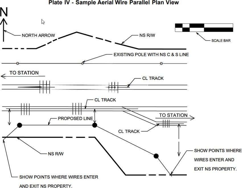
NSCE-4
                                                                                                                                                               4/23/2021
                                                                            INDEX
                                                                                                                                                                       Page
1.0   GENERAL

      1.1        Scope ............................................................................................................................................... 1

      1.2        Definitions ....................................................................................................................................... 1

      1.3        Application for Occupancy .............................................................................................................. 1

      1.4        Right of Entry .................................................................................................................................. 1

      1.5        Site Inspection ................................................................................................................................. 2

      1.6        Information Required for Submission ............................................................................................. 2

      1.7        Notification to Proceed with Construction ...................................................................................... 3

2.0   CONSTRUCTION REQUIREMENTS

      2.1        Aerial Wirelines ............................................................................................................................... 3

      2.2        Underground Wirelines ................................................................................................................... 4

      2.3        Method of Installation for Underground Wirelines ......................................................................... 5

      2.4        Longitudinal Occupations ................................................................................................................ 7

      2.5        Inductive Interference ...................................................................................................................... 8

      2.6        Modification of Existing Facilities .................................................................................................. 8

      2.7        Abandoned Facilities ....................................................................................................................... 8

      2.8        Conflict of Specifications ................................................................................................................ 8

      2.9        Marker Signs ............................................................................................................................................. 8

      2.10       Warning Tape .................................................................................................................................. 9

      2.11       Handholes ........................................................................................................................................ 9

      2.12       Safety Requirements ........................................................................................................................ 9

      2.13       Blasting ............................................................................................................................................ 9

      2.14       Support of Excavation Adjacent to Track ....................................................................................... 9

      2.15       Reimbursement of NS Costs .......................................................................................................... 10

      Publication Standards Sources ..................................................................................................................... 10

                                                                                   I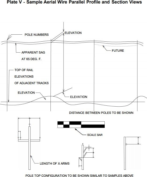
NSCE-4
                                                                                                                                        4/23/2021
                                                            APPENDIX

PLATE I      Conduit Data Sheet ................................................................................................................... 11

PLATE II     Aerial Crossing Plan View ............................................................................................... 12

PLATE III    Aerial Crossing Profile View ............................................................................................ 13

PLATE IV     Aerial Parallel Occupancy Plan View .............................................................................. 14

PLATE V      Aerial Parallel Occupancy Profile and Section Views...................................................... 15

PLATE VI     Conduit Crossing Plan View ............................................................................................ 16

PLATE VII    Conduit Crossing Profile View ......................................................................................... 17

PLATE VIII   Conduit Parallel Occupancy Plan and Profile Views........................................................ 18

PLATE IX     Conduit Parallel Occupancy Section View ....................................................................... 19

PLATE X      Conduit Plan and Section under Railway Bridge ............................................................. 20

PLATE XI     Conduit Profile and Section on Highway over Railway ................................................... 21

PLATE XII    Signal Clearance Diagram for Mast Mounted Flashers .................................................... 22

PLATE XIII   Signal Clearance Diagram for Cantilever Mounted Flashers............................................ 23

PLATE XIV    Vertical Clearance Requirements for Aerial Wires .......................................................... 24

                                                              II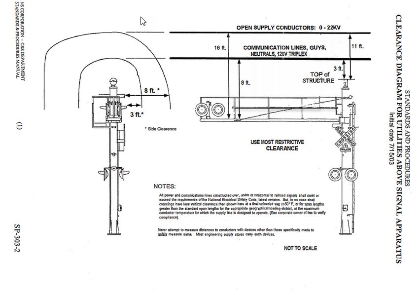
NSCE-4
                                                                                                          4/23/2021
      Specifications for Wireline Occupancy of Norfolk Southern Property
1.0   GENERAL

1.1   Scope

      A. This specification shall apply to the design and construction of wirelines carrying power or
         communication cables over, under, across and along NS property and facilities. This specification shall
         also apply to tracks owned by others (sidings, industry tracks, etc.) over which NS operates its
         equipment.

      B. It is to be clearly understood that NS owns its property for the primary purpose of operating a railroad.
         All occupancies shall therefore be designed and constructed so that rail operations and facilities are not
         interfered with, interrupted or endangered. In addition, the proposed facility shall be located to
         minimize encumbrance to the property so that the railroad will have unrestricted use of its property for
         current and future operations.

1.2   Definitions

      A. NS                            -       Norfolk Southern Corporation

      B. Applicant (Owner)             -       Individual, corporation or municipality desiring occupancy of NS
                                               property

      C. Professional Engineer         -       Engineer licensed in the state where the facilities are to be
                                               constructed

      D. Conduit                       -       Pipe, 6-inches in diameter or less, used to transport a wireline

      E. Sidings or industry tracks    -       Tracks located off NS’s property, serving an industry

1.3   Application for Occupancy

      A. Individuals, corporations or municipalities desiring occupancy of NS property by wireline occupations
         must agree, upon approval of the engineering and construction details by NS, to execute an appropriate
         NS occupational license agreement, pay any required fees and/or rentals outlined in the agreement, and
         meet all NS insurance requirements.

      B. The application process and guidelines for a wireline crossing occupancy can be found at
         www.nscorp.com, then follow links for Real Estate > NS Services > Wire, Pipeline, and Fiber Optics
         Projects.

      C. All applications shall be submitted through the web based application portal at
         https://ns.railprospermitting.com and require a pdf copy of all design and construction plans and a
         copy of all specifications and engineering computations for the proposed occupancy. On extensive
         projects, only those plans involving work on, or affecting NS property and operations, shall be
         submitted. Included shall be a plan showing the extent of the total project upon which that portion of
         the work affecting NS is clearly defined.

1.4   Right of Entry

      A. No entry upon NS property for the purpose of conducting surveys, field inspections, obtaining soils
         information or any other purposes associated with the design and construction for the proposed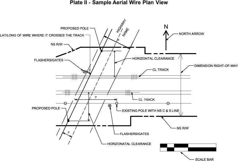
NSCE-4
4/23/2021
occupancy will be permitted without a proper entry permit. The applicant must pay the associated
fees and execute the entry permit.
B. It is to be clearly understood that the issuance of an entry permit does not constitute authority to
proceed with any construction. Construction cannot begin until a formal agreement is executed by NS
and the applicant receives permission to proceed with the work from the designated construction
monitoring agency of NS.
C. The application for a Right of Entry permit shall be obtained at www.nscorp.com then follow links for
Real Estate > NS Services > Access NS Property.
1.5 Site Inspection
A. Site inspection is required for all new installations, construction activities, removal and/or
modifications to existing facilities.
B. For longitudinal occupancy of NS property, a site inspection along the proposed wireline route may
be required before final design plans are prepared. When a site inspection is required, the applicant
and/or his engineer must meet with representatives of NS to view the entire length of the proposed
occupancy.
C. Prior to the site inspection the applicant must submit the following information through the application
portal:
(1) A plan view of the proposed route showing all tracks, both NS property lines and all other facilities
located on the property. The distance from the proposed wireline to the adjacent track and to the
property lines must be shown.
(2) Typical cross sections along the proposed route. (See Plate IX)
D. See Section 2.0 for further details.
1.6 Information Required for Submission
A. Plans for proposed wireline occupancies shall be submitted to and approved by NS or its representative
prior to issuance of an agreement and start of construction.
B. Plans shall be drawn to scale, dimensioned with US Customary Units, and shall include the following
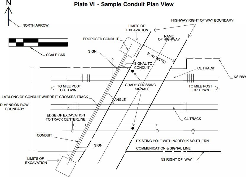
(See Plates I to IX):
(1) Plan view of proposed wireline in relation to all NS facilities and facilities immediately adjacent to
NS including, but not limited to, tracks, buildings, signals, pole lines, other utilities and all other
facilities that may affect or influence the wireline design and construction.
(2) The geographical coordinates (latitude and longitude) of the wire crossing including the
distance, in feet, to the nearest highway grade crossing of the railroad and the DOT number
posted at the highway grade crossing, if available.
(3) Profile of ground on centerline of pole or tower line showing clearances between top of high rail
and bottom of sag accounted for wire type and thermal variation, as well as clearances from
bottom wire or cable to top wire or cable of NS’s transmission, signal and communication lines,
catenary, and third rail when present. If NS facilities listed above do not exist at the point of
crossing, the plan should so state. Actual vertical clearance shall be shown. (See Section 2.1 and
Plate XIV for the required overhead clearance.)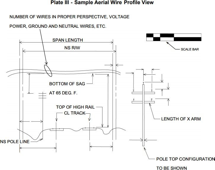
NSCE-4
                                                                                                           4/23/2021
          (4) All NS property lines indicated by dimensions, in feet, to the centerline of adjacent track, as well as
              the overall width of the NS property. If the wireline is in a public highway, the limits of the
              dedicated highway property, as well as the limits of any paving, sidewalks etc., shall be defined, by
              dimensions in feet, from the centerline of the dedicated property.
          (5) The angle of the crossing in relation to the centerline of the tracks(s).

      C. The plan must be specific, as to:

          (1) Base diameter, height, class and bury of poles.

          (2) Number of, size, and material of all wires, as well as number of pairs/strands in
              communication cables.

          (3) Nominal voltage of line and phase of circuit.

          (4) Location, number of, size of, material or anchors and all guying for poles and arms.

          (5) Conduit length across property lines.

          (6) Areas of impact and/or vegetation removal.

      D. Once the application has been approved, no variance from the plans, specifications, method of
         installation, and construction, etc., as approved in the occupancy document, will be considered or
         permitted without the payment to NS or its representative of additional fees for the re-processing of
         the application.
      E. Under special conditions, NS will give consideration to occupations on its bridge superstructures,
         substructures, pole line, and other subject to the approval of the VP-Engineering or designated
         representative, and NS policy governing such matters.

      F. At NS’s request, all plans and computations associated with the work under the agreement shall
         be prepared by, and bear the seal of, a Professional Engineer and Professional Land Surveyor.
      G. Project specifications, for all work on and affecting the NS property, shall be included with the
         submission. All pertinent requirements of this document shall be included.

1.7   Notification to Proceed with Construction

      A. After approval of the engineering plans, specifications, and execution of the occupational agreement,
         the applicant will be notified of the appropriate NS representative that must be contacted prior to
         start of construction. The NS representative will coordinate all other construction aspects of the
         project that relate to NS including but not limited to construction monitoring, flagging, track work,
         and protection of signal cables.

2.0   CONSTRUCTION REQUIREMENTS

2.1   Aerial Wirelines

      A. Overhead power and communication lines shall be constructed in accordance with the National
         Electrical Safety code (current edition), Part 2, “Safety Rules for the Installation and Maintenance of
         Overhead Electric Supply and Communication Lines”, except as outlined further in this section.

      B. Poles including guy cable, subs, or anchors shall be located as close to NS property line as possible
         and in no instance closer than 28-feet from face of pole to centerline of nearest track.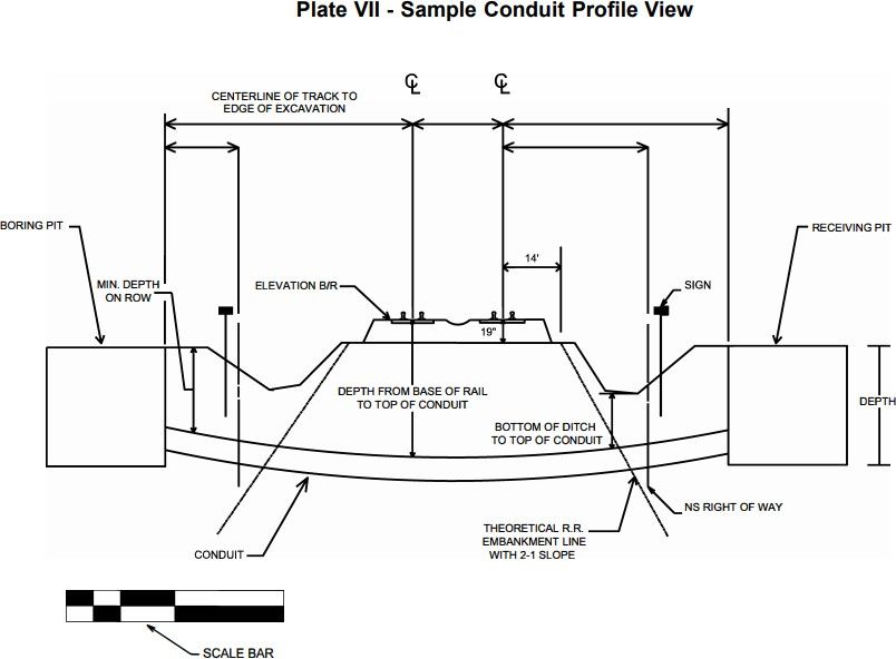
NSCE-4
                                                                                                          4/23/2021
      C. Double cross-arms are required on poles adjacent to track. Any tower or steel pole foundation design
         must be accompanied by engineering computations and data stamped by a registered Professional
         Engineer of the state in which the project is located.

      D. Any tower or steel pole to be installed on NS property must meet or exceed the industry standards
         regarding design and usage.

      E. Vertical clearance from the top of rail to the bottom of sag of aerial wire crossing, measured at 60-
         degrees Fahrenheit, shall be as follows:

       Guy wires, messenger cables,          Electric supply lines and neutral wires (voltage is measured phase-to-
       and telecommunication cables          ground) *
                                              Less than 750-V         750-V to 15-KV             15-KV to 50-KV
                     27-feet
                                                  30-feet                 31-feet                    33-feet
      * For electric supply lines or neutral wires carrying greater than 50-KV, use a vertical clearance of 33-feet
        plus ½-inch per 1-KV above 50-KV.

      F. Vertical clearance between proposed aerial wire crossings and aerial Norfolk Southern communications
         lines shall be as follows:

       Guy wires, messenger cables,          Electric supply lines and neutral wires (voltage is measured phase-to-
       and telecommunication cables          ground) *
                                              Less than 750-V         750-V to 15-KV             15-KV to 50-KV
                      2-feet
                                                   2-feet                  4-feet                    6-feet
      * For electric supply lines or neutral wires carrying greater than 50-KV, use a vertical clearance of 33-feet
        plus ½-inch per 1-KV above 50-KV.

      G. Overhead power and communication lines shall be constructed in accordance with the Signal Clearance
         Diagrams as seen in Plate XII and XIII.

2.2   Underground Wirelines

      A. Underground installations carrying power or communication wires and cables shall be constructed and
         properly marked with signs, in accordance with American Railway Engineering Maintenance-of-Way
         Association (current edition), Chapter 1, Part 5, except as outlined further in this section.

      B. Conduits shall be located, where practicable, to cross tracks at approximate right angles to the track,
         but preferably at not less than 45-degrees.

      C. Conduits shall not be placed within a culvert, under railroad bridges, nor closer than 50-feet to any
         portion of any railroad bridge, building, or other important structure, except in special cases, and then
         by special design, as approved by NS or its authorized representative.

      D. Conduits shall not be located within 50 feet of the limits of a turnout (switch) when crossing the track.
         The limits of the turnout extend from the point of the switch to the last long timber.

      E. Conduit shall not be located within 50 feet of a control point area. The limits of the control point area
         are governed by the signal system regulating the control point.

      F. Plastic conduit material includes thermoplastic and thermoset plastic conduits, such as PVC and HDPE.

      G. Conduits shall maintain a minimum horizontal clearance of 4-feet, or if within 4-feet, a minimum
         vertical clearance of 10-feet from the base of any railroad signal apparatus.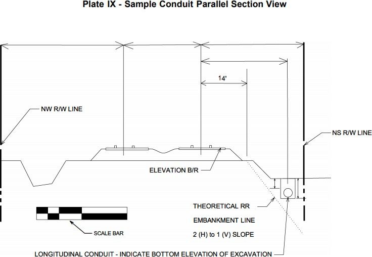
NSCE-4
                                                                                                          4/23/2021

      H. Minimum Depth of Installation:

            Material                     Bore & Jack                     HDD-A                    HDD-B
            Steel                           5.5-feet                     10-feet                  5.5-feet
            Plastic                                                     15-feet*
            Parallel Occupancy                                            4-feet
           * Within 25-feet of centerline of the closest track and a minimum depth of 10-feet anywhere else on NS
             property.

      I.   Conduits under railroad tracks and across NS’s property shall extend the greater of the
           following distances, measured at right angle to centerline of track:

           (1) Across the entire width of the NS property

           (2) 3-feet beyond ditch line

           (3) 2-feet beyond toe of slope

           (4) Beyond theoretical railroad embankment line. This line begins at a point, on existing grade, 14-
               feet horizontally from centerline track and extends downward on a 2 (H) to 1 (V) slope. (See Plate
               VII) The 14-foot is measured from 19-inches below the base of the rail.

2.3   General track and ground monitoring requirements
        (1) General requirement
                 a. Temporary lighting may also be required by the NS to identify tripping hazards to train
                    crewmen and other NS personnel.
                 b. Any excavation, holes or trenches on the NS property shall be covered, guarded and/or
                    protected. Handrails, fence, or other barrier methods must meet OSHA and FRA
                    requirements.
           (2)   Track and ground monitoring are required as follows:
                 a. For crossings with pipe diameter and depth (below base of rail) as shown below in
                 b. For shoring within Zone 1 of any track, as shown below in PLATE VIII.
                 c. Additional monitoring may be required by the NS on a case by case basis.
           (3)   Monitoring schedule
                 a. Monitoring shall commence once any construction activity is within Zone 1. See PLATE
                    VIII.
                 b.    Monitoring shall continue through completion of installation and may be required after
                      completion for a period of time determined by NS or its representative.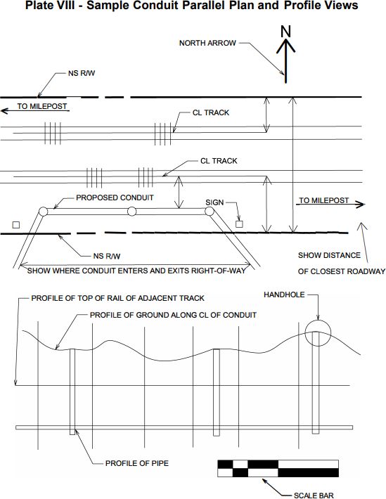
NSCE-4
                                                                                                                  4/23/2021

                                                           Final Bore Hole, inches

                                             1-5   6-12      12-24    24 - 42   42 - 54 54 - 60    >60

          (below base of rail)
             Depth, feet               5 X         X        X        X          X       X         X
                                      10 X         X        X        X          X       X         X
                                      15           X        X        X          X       X         X
                                      20                    X        X          X       X         X
                                      25                             X          X       X         X
                                      30                                        X       X         X
                                     >30                                                X         X
                                                       X = Track Monitoring is required

B. Track Monitoring
   (1) Track Deflection Limits
   (2) Targets
         a. Track monitoring shall not require track access other than to place the track monitoring
            targets.
         b. Monitoring targets should be placed such that monitoring is possible when a train is present.
            However, monitoring during the passing of a train is not required as the train will
            temporarily deflect the track.
         c. Adhesive backed reflective targets may be attached to the side of the rail temporarily.
            Targets should be removed once monitoring phase is complete.
   (3) Monitoring Plan
   (4) If the top of rail does deflect more than values listed below, all operations shall stop until the
       matter is resolved.
         a. Track monitoring values for Class 3 through Class 4:
            1. Threshold value = 1/8 inch permanent vertical or horizontal deflection
                    2. Installation Shutdown value = 1/4 inch permanent vertical or horizontal deflection
         b. Track monitoring values for Class 1 through Class 2:
                    1. Threshold value = 1/4 inch permanent vertical or horizontal deflection
                    2. Installation Shutdown value = 1/2 inch permanent vertical or horizontal deflection
         c. Provide established contingency plan, see Section D, in the event of ground loss and/or the
            rail deviates ¼ inch vertical or horizontal.
         d. Establish a benchmark in the vicinity of the construction. Establish locations for shooting
            elevations on the top of rail at each area of construction.
                    1. Example locations for shooting rail elevations would be at:
                                 •   At the centerline of an under track crossing.
                                 •   At both outside edges of the crossing i.e. for a wide excavation.
                                 •   At multiple locations from the crossing/excavation edge but no less than 10, 20, 30,
                                     40 and 50 feet from the crossing.
         e. Monitoring shall be continuous and recorded in a field logbook dedicated for this purpose.
            Copies of these field log entries can be made available to all concerned parties upon request
            at any time during construction.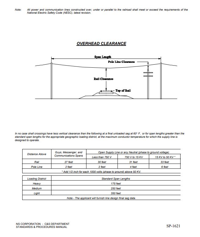
NSCE-4
                                                                                                          4/23/2021

      C. Ground Monitoring
         (1) Provide means for monitoring ground settlement. Submit monitoring plan for NS review.
         (2) Ground monitoring points should be in alignment above the proposed construction activities.

      D. Contingency Plans
         (1) The Contractor shall supply Contingency Plan(s), which anticipate reaching the Threshold and
             Installation Shutdown values, for all construction activities which may result in horizontal and/or
             vertical track deflection.
                a. Track monitoring values for Class 3 through Class 4:
                    1. Threshold value = 1/8 inch permanent vertical or horizontal deflection
                    2. Installation Shutdown value = 1/4 inch permanent vertical or horizontal deflection
                b. Track monitoring values for Class 1 through Class 2:
                    1. Threshold value = 1/4 inch permanent vertical or horizontal deflection
                    2. Installation Shutdown value = 1/2 inch permanent vertical or horizontal deflection
         (2) The Contingency Plans shall provide means and methods, with options if necessary.
         (3) The Contractor should anticipate the need to implement each Contingency Plan with required
             materials, equipment and personnel.
                a. Once the Threshold value is met, the contractor shall determine the appropriate Contingency
                   Plan(s) and immediately discuss this plan with, and receive approval confirmation from, the
                   NS.
                b. Once the Installation Shutdown value is exceeded all project work shall stop and the chosen
                   Contingency Plan shall commence.
                   1. The NS may choose to allow and/or require the immediate implementation of specific
                      approved Contingency Plans, submitted by the contractor, once the Installation
                      Shutdown value is exceeded.

2.4    Method of Installation for Underground Wirelines:

       A. Bored, jacked or tunneled installations shall have a bore hole essentially the same as the
           outside diameter of the conduit plus the thickness of the protective coating.

       B. The use of water or other liquids to facilitate conduit emplacement and spoil removal is prohibited,
           except as outlined in Section F.

       C. If during installation an obstruction is encountered which prevents installation of the conduit in
           accordance with this specification, the conduit shall be abandoned in place and immediately filled with
           grout. A new installation procedure and revised plans must be submitted to, and approved by, NS or
           its representative before work can resume.

       D. The project specifications must require the contractor to submit, to NS or its representative for
           approval, a complete construction procedure of the proposed operations. Included with the
           submission shall be the manufacture’s catalog information describing the type of equipment to
           be used.

       E. Bore and Jack (Steel Pipe)
           This method consists of pushing the pipe into the earth with a boring auger rotating within the pipe to
           remove the spoil.
NSCE-4
4/23/2021
(1) The boring operation shall be progressed on a 24-hour basis without stoppage in Zone 1, 2, and
3 as indicated in Plate VIII of NSCE-8 “Specification for Pipeline Occupancy of Norfolk
Southern Corporation Property” (except for adding lengths of pipe) until the leading edge of the
pipe has reached the receiving pit.
(2) The front of the pipe shall be provided with mechanical arrangements or devices that will
positively prevent the auger from leading the pipe so that no unsupported excavation is ahead
of the pipe.
(3) The auger and cutting head arrangement shall be removable from within the pipe in the event an
obstruction is encountered. If the obstruction cannot be removed without excavation in advance
of the pipe, procedures as outlined in Section 2.3.C must be implemented immediately.
(4) The over-cut by the cutting head shall not exceed the outside diameter of the pipe by more than½-
inch. If voids should develop or if the bored hole diameter is greater than the outside diameter of
the pipe (plus coating) by more than approximately 1-inch, grouting or other methods approved by
NS or its representative, shall be employed to fill such voids.
(5) The face of the cutting head shall be arranged to provide a reasonable obstruction to the free
flow of soft or poor material.
(6) Any method that employs simultaneous boring and jacking for conduits over 8-inches in diameter
that does not have the above approved arrangement will not be permitted. For pipe 8-inches and
less in diameter, auguring or boring without this arrangement may be considered for use only as
approved by NS or its representative.
F. Directional Boring / Horizontal Directional Drilling Method “A”
This method consists of setting up specialized drilling equipment on existing grade (launching and
receiving pits are not required) and boring a small diameter pilot hole on the desired vertical and
horizontal alignment, using a mechanical cutting head with a high pressure fluid (bentonite slurry) to
remove the cuttings. The drill string is advanced with bentonite slurry pumped through the drill string
to the cutting head and then forced back along the outside of the drill string, carrying the cuttings back
to the surface for removal. When the cutting head reaches the far side of the crossing, it is removed
and a reamer (with a diameter greater than the cutting head) is attached to the lead end of the drill
string. The conduit is attached to the reamer and the pilot hole is then back reamed while the conduit is
pulled into place.
(1) For steel conduits, the depth of cover must be greater than 10-feet below the base of the rail, or the
bore is in rock.
(2) For plastic conduits, the depth of cover must be greater than 15-feet below the base of the rail, or
the bore is in rock.
(3) Factors considered will be track usage, pipe size, contents of pipeline, soil conditions, etc.
(4) For conduits that are over 6 inches, steel conduit casing must be use and maximum size of any conduit
shall be limited to 8 inches.
(5) Multiple innerducts must be in a casing 6” or less in diameter. For casing over 6 inches refer to
Section 2.4 F (4). Provide a detail or cross section of the casing pipe with innerducts. Please see detail
on the Conduit Data Sheet, Plate I. Clearly mark the type of facility that will be installed with each
innerduct. If innerduct will be left spare or empty, please identify as such.NSCE-4
4/23/2021
G. Directional Boring / Horizontal Directional Drilling Method “B”
This method consists of using hydraulic jacking equipment to push a solid steel rod under the railroad
from a launching pit to a receiving pit. At the receiving pit, a cone shaped “expander” is attached to the
end of the rod and the conduit (casing pipe) is attached to the expander. The rod, expander and conduit
are then pulled back from the launching pit until the full length of the conduit is in place.
(1) This method may be used to place conduit (casing pipe), up to and including 6-inches in diameter,
under the railroad.
(2) For steel conduits, the depth of cover must be greater than 5.5-feet below the base of the rail, or the
bore is in rock.
(3) For plastic conduits, the depth of cover must be greater than 15-feet below the base of the rail, or
the bore is in rock.
(4) For conduits that are over 6 inches, steel conduit casing must be use and maximum size of any conduit
shall be limited to 8 inches.
(5) Multiple innerducts must be in a casing 6” or less in diameter. For casing over 6 inches refer to
Section 2.4 G (4). Provide a detail or cross section of the casing pipe with innerducts. Please see detail
on the Conduit Data Sheet, Plate I. Clearly mark the type of facility that will be installed with each
innerduct. If innerduct will be left spare or empty, please identify as such.
2.5 Longitudinal Occupations
A. Conduits laid longitudinally on NS property shall be located as far as practicable from any tracks or
other important structures and as close to the NS property line as possible. Longitudinal conduits
must not be located in earth embankments or within ditches located on the property.
B. Feasibility proposals will be accepted for review. Applicant should furnish a letter requesting study
along with a plan view showing the extent of the proposed occupation. This feasibility plan may
being the form of a local, county, USGS Map, or drawing, showing the railroad, streets, highways
and other information identifying the location of the project.
C. Arrangements will then be made to furnish the applicant with the appropriate NS valuation maps and a
right of entry permit. There will be a “nominal charge” for the necessary valuation maps which depict
the NS property lines and other facilities. These are the best records we have and may be used for the
feasibility proposal. However, NS does not warrant the accuracy of these maps and all pertinent
information to the NS occupancy must be verified prior to final submission.
D. Upon receipt of these documents, the applicant must execute the right of entry permit in order to
access NS property. Such access would allow for the verification that the proposed pole locations are
feasible and do not interfere with any NS facilities. At such a time, the applicant should stake out a few
“key” points along with the occupation such as, crossings, alignment, radical changed in alignment,
etc.
E. Once this temporary stake out is completed, the applicant must submit to NS via the online application
portal, a PDF copy of preliminary plans showing the location of all proposed poles and other
information as stated below. Arrangements will then be made for a site investigation by NS personnel.
The proposed occupation will be field checked to ensure compliance with and conformance to this
specification. At that time, comments, recommendations, changes to, or approval of, all locations will
be made.NSCE-4
4/23/2021
F. Wires and cables running longitudinally along NS’s property shall be constructed as close to property
lines as possible. The following information must be submitted in addition to the detail of the pole top
configuration as called for on Plate V of these specifications:
(1) Nominal voltage and phase of circuit(s) or number of pairs.
(2) Phase of electrical circuit(s).
(3) Number of electrical circuits.
(4) Size (AWG or CM) and material of wires or cables.
(5) Length of spans clearly indicated on drawing.
(6) Any intended future wires or cables.
G. Any facilities overhanging or requiring a clear zone on NS property must have approval of the VP-
Engineering or his designated representative; must confirm to the above specifications and are subject
to the appropriate rental charges.
H. Project specifications, for all work on and affecting the NS property, shall be included with the
submission. All pertinent requirements of this document shall be included.
2.6 Inductive Interference
A. An inductive interference coordination study is required for all proposed longitudinal occupations.
This study may also be required for any crossing other than 90-degrees with the track(s).
B. All agreements covering crossings and longitudinal occupations will include provisions that the
applicant provide appropriate remedies, at his own expense, to correct any inductive interference with
NS facilities.
2.7 Modification of Existing Facilities
A. Any replacement or modification of an existing carrier pipe, conduit, and/or casing shall be
considered as anew installation, subject to the requirements of this specification.
2.8 Abandoned Facilities
A. The owner of all abandoned conduit crossings and other occupancies shall notify NS in writing, of
the intention to abandon. The owner of conduit crossings and other occupancies shall submit to NS a
request to abandon through the application portal and shall include its abandonment plans.
B. Abandoned conduits shall be completely filled with cement grout, compacted sand or other methods as
approved by NS. This criterion maybe waived by NS for all, or a portion of the occupancy, at its sole
discretion on case by case basis as requested by the applicant.
C. Abandoned handholes and other structures shall be removed to a minimum distance of 3-feet below
finished grade and completely filled with cement grout or compacted sand.
2.9 Conflict of Specifications
A. Where laws or orders of public authority prescribe a higher degree of protection than specified herein,
then the higher degree so prescribed shall be deemed a part of this specification.
2.10 Marker SignsNSCE-4
4/23/2021
A. Conduits shall be prominently marked 15-feet from the centerline of nearest track (except those in
streets or access roads, where it would not be practical to do so or would interfere with NS operations)
and at property lines at points of entry/exit (on both sides of track for crossings) by durable,
weatherproof signs located over the centerline of the conduit. Signs shall show the following:
(1) Name and address of applicant
(2) Contents of conduit
(3) Emergency telephone number
B. For conduits running longitudinally on NS property, signs shall be placed over the conduit (or offset
and appropriately marked) at all changes in direction of the conduit. Such signs should also be located
so that when standing at one sign the next adjacent marker in either direction is visible. In no event
shall they be placed more than 500-feet apart unless otherwise specified by NS.
C. The applicant must maintain all signs on NS property as long as the occupational agreement is in effect.
2.11 Warning Tape
A. All conduits installed by open cut and handholes installed on NS property shall have
detectable underground warning tape placed minimum distance of 18 inches below the finished
ground surface elevation and located directly above the conduit.
2.12 Handholes and Manholes
A. Handholes and manholes shall not be located on NS property where possible. At locations where this
is not practical, including longitudinal occupancies, handholes and manholes on NS property shall have
a minimum of 2-feet of cover and be designed to withstand passage of trucks. Handholes and
manholes must be locatable from the surface.
B. The distance from centerline of adjacent track to centerline of proposed handhole and manholes shall
be shown on the plans.
2.13 Safety Requirements
A. All operations shall be conducted so as not to interfere with, interrupt, or endanger the operation of
trains or damage, destroy, or endanger the integrity of railroad facilities. All work on or near NS
property shall be conducted in accordance with NS safety rules and regulations. The contractor shall
secure and comply with the NS safety rules and shall give written acknowledgement to NS that they
have been received, read, and understood by the contractor and its employees. Operations will be
subject to NS monitoring at any and all times.
B. All cranes, lifts, or other equipment that will be operated in the vicinity of the railroad’s electrification
and power transmission facilities shall be electrically grounded as directed by NS.
C. At all times when the work is being progressed, a field supervisor for the work with no less than twelve
(12) months experience in the operation of the equipment being used shall be present. If boring
equipment or similar machines are being used, the machine operator also shall have no less than twelve
(12) months experience in the operation of the equipment being used.
D. Whenever equipment or personnel are working closer than 15-feet from the centerline of an adjacent
track, that track shall be considered as being obstructed. Insofar as possible, all operations shall be
conducted no less than this distance. Operations closer than 15-feet from the centerline of a track shall
be conducted only with the permission of, and as directed by, a duly qualified NS railroad employee or
an authorized NS representative present at the site of the work.NSCE-4
4/23/2021
E. Construction near switching areas may require lighting.
F. Crossing of tracks at grade by equipment and personnel is prohibited except by prior arrangement with,
and as directed by NS.
2.14 Blasting
A. Blasting will not be permitted.
2.15 Support of Excavation Adjacent to Track
A. The location and dimensions of all pits or excavations shall be shown on the plans. The distance from
centerline of adjacent track to face of pit or excavation shall be clearly labeled. Also, the elevation of
the bottom of the pit or excavation must be shown on the profile.
B. The face of all pits shall be located a minimum of 25-feet from centerline of adjacent track, measured
at right angles to track, unless otherwise approved by NS.
C. If the bottom of the pit excavation intersects the theoretical railroad embankment line (See Plate VII)
interlocking steel sheet piling, driven prior to excavation, must be used to protect the track stability.
The uses of trench boxes or similar devices are not acceptable in this area.
9
(1) Design plans and computations for the pits, stamped by a Professional Engineer, and must be
submitted by the applicant at time of application or by the contractor prior to start of construction.
If the pit design is to be submitted by the contractor, the project specifications must require the
contractor to obtain NS approval prior to beginning any work on or which may affect NS property.
(2) The sheeting shall be designed to support all lateral forces caused by the earth, railroad and other
surcharge loads.
(3) After construction and backfilling, all sheet piling within 10-feet of centerline track must be cut off
18-inches below final grade and left in place.
D. All excavated areas are to be illuminated (flashing warning lights not permitted), fenced and
otherwise protected as directed by NS.
2.16 Reimbursement of Costs
A. All costs incurred by NS or its representative associated with the wire installation (construction
monitoring, flagging, track work, protection of signal cables, etc.) shall be reimbursed by the
applicant.NSCE-4
4/23/2021
PUBLICATION STANDARDS SOURCES
ANSI American National Standards Institute, Inc.
1899 L Street, NW,
11th Floor Washington,
DC 20036
Tel: 202.293.8020
AREMA American Railway Engineering Maintenance-of-Way
Association 4501 Forbes Blvd., Suite 130
Lanham, MD 20706
Tel: 301.459.3200
ASTM American Society for Testing and
Materials 100 Barr Harbor Drive,
PO Box C700 West Conshohocken,
PA 19428
Tel: 610.832.9500
NESC National Electrical
Safety Code 445 Hoes
Lane
Piscataway, NJ 08854-
4141 USA Tel:
732.981.0060
NOTE: If other than ANSI, AREMA, ASTM or NESC specifications are referred to for design, materials or
workmanship on the plans and specifications for the work, then copies of the applicable sections of such other
specifications referred to shall accompany the plans and specifications for the work.PLATE I - Conduit Data Sheet
(For Telecom and Power Conduits only, 6” in diameter or less)
CONDUIT / CASING
PIPE
NOMINAL SIZE OF PIPE
MATERIAL*
OUTSIDE DIAMETER
INSIDE DIAMETER
WALL THICKNESS - must be at least 0.188”
TYPE OF COATING
* STEEL conduits required at least 10’ depth below base of rail
HDPE conduits will be considered at least 15’ depth below base of rail
Proposed Method of Installation (Given sections refer to NSCE-8 Specification)
Jack & Bore (Section 5.1.3)
Directional Boring Method “A” (Section 5.1.6) – must have at least 10’ depth below base of rail
Directional Boring Method “B” (Section 5.1.6) – only for casings 6 inches or less in diameter
Open Cut (Section 5.1.2) – All installations directly under any track must be designed as a
bored installation. Open cut installations will be considered on a case-by-case basis by Norfolk
Southern’s Division Superintendent at the time of installation.
Other – Please Specify:
MULTIPLE INNERDUCTS
NUMBER OF INNERDUCTS WITHIN CASING PIPE:
- Provide a detail or cross section of the casing pipe with innerducts (see below).
- Clearly mark the type of facility that will be installed within each innerduct. If innerduct will be
left spare or empty, please identify as such.Timetable Direction
(N, S, E or W)
Proposed Crossing:
Beginning/ End or
Intersecting Milepost.Looking Direction should be Increasing and Decreasing Milepost
Timetable Direction
(N, S, E or W)
Proposed Crossing:
Beginning/ End or
Intersecting Milepost within
NS Property.Looking Direction should be Increasing and Decreasing Milepost
Timetable Direction
  (N, S, E or W)

                      Proposed Crossing:
                      Beginning/ End or
                      Intersecting Milepost.
Looking Direction should be Increasing and Decreasing Milepost
Timetable Direction (N, S, E or W) Looking Direction should be Increasing and Decreasing Milepost
Looking Direction should be
Increasing and Decreasing Milepost
Timetable Direction
(N, S, E or W)
Looking Direction should be
Increasing and Decreasing MilepostLooking Direction should be Increasing and Decreasing Milepost
PLATE XII - Signal Clearance Diagram for Mast Mounted Flashers and Gates
PLATE XIII - Signal Clearance Diagram for Cantil ever Mounted Flashers and Gates
PLATE XIV - STANDARDS AND PROCEDURES
CLEARANCE REQUIREMENTS FOR CABLE AND WIRE CROSSINGS Initial date
                    9/1/93 - Revised 3/24/06
You can also read