Servo Cartridge Pump Owner's Manual Revision A
←
→
Page content transcription
If your browser does not render page correctly, please read the page content below
INNOVATION. PRECISION. EXCELLENCE.

Servo Cartridge Pump
          Owner’s Manual
                    Revision A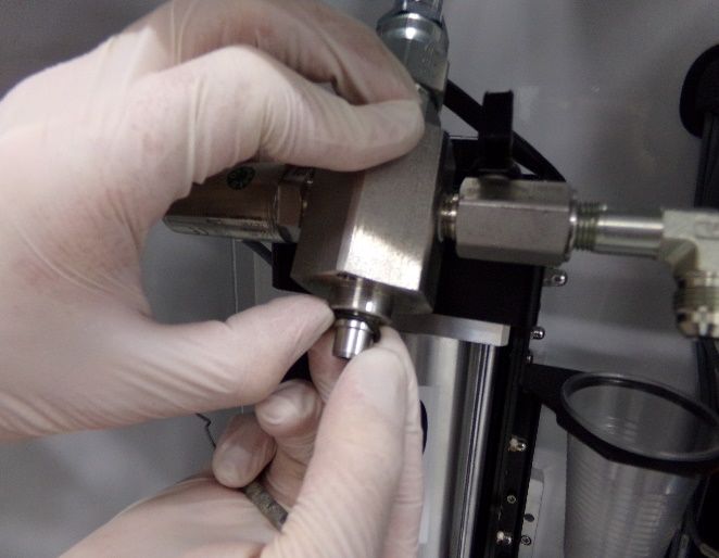
SCTP Operation Manual

This document is based on information available at the time of its publication. While efforts
have been made to ensure the contents of this manual are accurate, the information
contained herein does not purport to cover all specific details or variations in hardware, or
to provide for every possible contingency in connection with installation, operation, or
maintenance. Features may be described herein which are not present in all hardware and
software systems. Precision Valve and Automation, Inc. assumes no obligation of notice to
holders of this document with respect to changes subsequently made.

Precision Valve and Automation, Inc. makes no representation or warranty, expressed,
implied, or statutory with respect to, and assumes no responsibility for the accuracy,
completeness, sufficiency, or usefulness of the information contained herein. No warranties
of merchantability or fitness for purpose shall apply.

This document, including the information contained herein, is the property of
Precision Valve and Automation, Inc. and is considered confidential and proprietary
information. It is delivered on the express condition that it not be used, disclosed, or
reproduced, in whole or in part, for any reason without prior written consent of
Precision Valve and Automation, Inc.

                                      Copyright © 2022

                            Precision Valve and Automation, Inc.

                                    All Rights Reserved.

                       Revision A / January 2022                           Page 2 of 32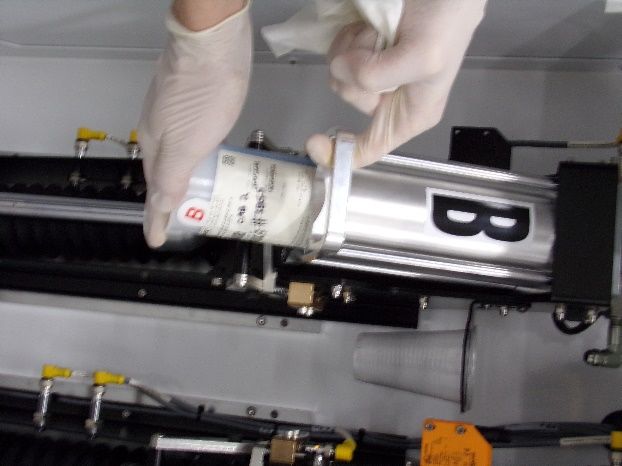
SCTP Operation Manual

Table of Contents
  Introduction ........................................................................................................... 5
        PVA Contact Information ........................................................................................................ 5
        Document History ..................................................................................................................... 5
        Safety ..........................................................................................................................................6
        Theory of Operation ................................................................................................................ 8
        Guidelines .................................................................................................................................. 8
        Description of Major Components ........................................................................................ 9
        Personal Protective Equipment ........................................................................................... 10
        Waste Disposal......................................................................................................................... 10
  Setup ...................................................................................................................... 11
        System Requirements ............................................................................................................11
        Machine Safety Features ...................................................................................................... 12
  Pre-Run Checks ................................................................................................... 13
  Operation Instructions ....................................................................................... 14
        Summary of Manual Cartridge Functions.......................................................................... 14
        How to Unload a Cartridge .................................................................................................... 15
        How to Load a Cartridge ........................................................................................................ 18
        How to Bleed the Cartridge System ................................................................................... 19
               To Bleed the System ..................................................................................................... 20

        Preload Pressure ..................................................................................................................... 21
        Depressurization ..................................................................................................................... 21
  Pump Settings .....................................................................................................22
        Pump Rate Adjustment ........................................................................................................ 22
        Preload Pressure Adjustment ............................................................................................. 22
  Maintenance ........................................................................................................23
        How to Replace an O-ring .................................................................................................... 23
  Plumbing Schematic ...........................................................................................25
  Spare Parts and Accessories.............................................................................26
  Technical Specifications.................................................................................... 27

                                Revision A / January 2022                                                                   Page 3 of 32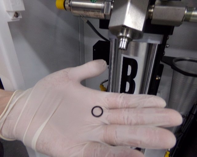
SCTP Operation Manual

Troubleshooting ................................................................................................. 28
Drawings ...............................................................................................................29
Notes .................................................................................................................... 30
Table of Figures ................................................................................................... 31
PVA Warranty Policy ...........................................................................................32

                         Revision A / January 2022                                                  Page 4 of 32
SCTP Operation Manual

   Introduction
Before you operate this system, read the operation and setup manual. This will help you to
become familiar with the product and ensure successful operation.

If any questions or problems arise, contact PVA’s Technical Support department.

         PVA Contact Information
Main Office          PVA

                     6 Corporate Drive

                     Halfmoon, NY 12065

                     Tel +1-518-371-2684

                     Fax +1-518-371-2688

                     Website: http://www.pva.net

                     Email: info@pva.net

Technical Support

                     Tel +1-844-734-0209

                     Email: cs@pva.net

         Document History
 Revision Revision Date           Reason for Changes

 REV A        May 2021            Initial Release

Note: All photographs and CAD model representations in this document are a
“general representation” of the system and its components. The actual appearance
of the system and its components can differ based upon customer specific
configuration.

                         Revision A / January 2022                        Page 5 of 32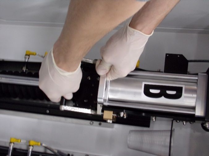
SCTP Operation Manual

        Safety
Certain warning symbols are affixed to the machine and correspond to notations in this
manual. Before operating the system, identify these warning labels and read the notices
described below. Not all labels may be used on any specific system.

              Always wear approved safety glasses when you operate or work near the
              workcell.

              Before you operate the system, read and understand the manuals provided
              with the unit.

              Never put hands or tools in areas with this symbol when the machine is in
              operation. A dangerous condition may exist.

              Read and understand the manuals provided with the unit before any
              repairs or maintenance is done. Only a qualified individual should do
              service.

              Use caution when there are pressurized vessels. Find and repair any leaks
              immediately. Always wear appropriate safety equipment when you work
              with pressurized vessels or vessels that contain chemicals.

              Shear hazard from moving parts. Avoid contact.

              Do not remove protective guarding.

              In situations where inattention could cause either personal injury or
              damage to equipment, a warning notice is used.

                      Revision A / January 2022                           Page 6 of 32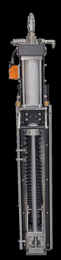
SCTP Operation Manual

Do not smoke near the machine. Always have a fire extinguisher available
for emergency use.

Before performing any repairs or maintenance to the system, turn off
power and lock out the power disconnect switch.

Warning notices are used to emphasize that hazardous voltages, current,
temperatures, or other conditions that could cause personal injury exist in
this equipment or may be associated with its use. Only qualified personnel
should enter areas designated with this symbol.

Laser light source present. Do not stare directly into the beam. Do not use
in the presence of highly reflective surfaces.

Pinch hazard from moving parts. Avoid contact.

Hot surface. Avoid contact.

Warning, Ultraviolet (UV) light hazard. Do not look directly at the UV light
source.

This product meets EU standards for health, safety, and environmental
protection.

Warning, no open flames.

Electrostatic sensitive device warning. Observe precautions for handling.

       Revision A / January 2022                              Page 7 of 32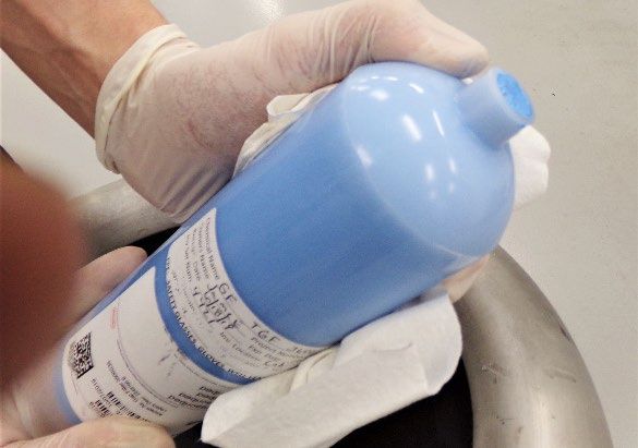
SCTP Operation Manual

        Theory of Operation
The SCTP Servo Cartridge Pump operates by metering material directly from disposable
plastic cartridges via a linear drive. There are no moving components or seals to wear,
providing a low maintenance solution. Configurations are available for both 20 & 32 oz
SEMCO® cartridges.

The SCTP can be used in single component or two component meter-mix applications.

Via a menu driven HMI, the closed loop servo drives enable programming of the following
functions:

   •   Shot Size
   •   Mix Ratio
   •   Flow Rate
   •   Pressure Control
   •   Auto Purge
   •   Optional Color Sensors
   •   Low Level Detection
The machine uses two rams to mechanically extrude material directly from the original
plastic cartridges. The rams are operated by the servo motors with closed loop controls
provided by the PVA workcell.

The operator must load and unload the cartridges into the system. PVA Portal software is
used to control the machine.

        Guidelines
This manual shows how to correctly operate the SCTP with the Endurance metering
system. This manual does not replace the manual for your PVA workcell.

   •   Follow material manufacturer’s recommendations.
   •   Make sure material was/is stored correctly.
   •   Make sure material is not expired.
   •   Relieve system pressure when the machine is not in use.
   •   Follow all instructions in this manual.

                       Revision A / January 2022                          Page 8 of 32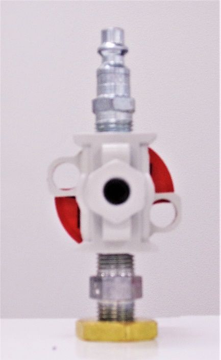
SCTP Operation Manual

        Description of Major Components
This table lists the major SCTP components.

      Component       Description

      Cartridge       The cartridge retainer holds the cartridge in position and
      Retainer        supports the cartridge while under pressure.

      Ram             The ram pushes against the plunger inside the cartridge and
                      extrudes the material out of the cartridge nozzle.

      Servo Motor     The motors are connected to gearboxes and control the
                      speed and direction of the ram.

      Purge Valve     A manual ball valve for the purpose of purging air or relieving
                      pressure.

      Locking         A handle used to secure the canister and lock the retainer in
      Lever           the dispense position.

      Pressure        Reads material pressure.
      Transducer

                    Figure 1: Overview of SCTP Servo Cartridge Pump Components

For an example of the major SCTP components, refer to the figure below.

                     Revision A / January 2022                                   Page 9 of 32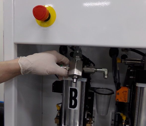
SCTP Operation Manual

                                                                       Pressure
                              Purge Valve                             Transducer

      Cartridge
      Retainer

   Locking
    Lever

      Ram

                   Figure 2: Endurance Machine with Servo Cartridge Pump Configuration

        Personal Protective Equipment
Operators must use eye protection because material contents are under pressure. Always
wear gloves when handling materials and solvents. Refer to Material Safety Data Sheet
(MSDS) sheets on the material being dispensed for other precautions.

        Waste Disposal
Dispose of all used parts and materials in accordance with local laws and regulations.

                        Revision A / January 2022                                        Page 10 of 32
SCTP Operation Manual
Setup
Before you operate the pump, know the pump components. Do the steps as instructed.
System Requirements
While the Endurance does not need to interface with a PVA workcell, this manual outlines
the correct use of the Endurance (equipped with SCTP) with a PVA Workcell.
Make Sure:
• All motor cables/sensor cables/communications are correctly connected from the
PVA workcell to the machine. Refer to the workcell schematics.
• All hoses, fittings, and valves are connected and tight. Refer to the PVA workcell
schematics for the correct plumbing layout.
• PVA workcell is powered up and supplied with the machine air pressure.
WARNING! Become familiar with and test all functionality of the machine before you
load any cartridges of material into the machine.
Figure 3: Airline Hookup and Electrical Hookup
Revision A / January 2022 Page 11 of 32SCTP Operation Manual
Machine Safety Features
The machine enclosure includes additional safety features including magnetic interlocks.
To operate the system or to change modes, the enclosure door must be closed. The purge
cups and valves can be monitored through the view window on the front of the machine.
Each cartridge retainer has a locking lever and a sensor to make sure the cartridge is
correctly locked in place before the ram engages. To prevent the mismatch of material
components, optional color sensors indicate when the correct cartridge is loaded.
WARNING: Do not attempt to bypass these safety features!
Figure 4: Machine with Rams in Home Position
Revision A / January 2022 Page 12 of 32SCTP Operation Manual
Pre-Run Checks
Most machine failures, down time, and injuries can be prevented by performing the
following pre-run checks:
1. Visually check the PVA workcell and the SCTP to make sure:
• There are no frayed/kinked wires or hoses.
• All wires and hose connections are tightly attached.
• There are no obstacles that interfere with the servo motors, rams, and X, Y, Z
motion in the PVA workcell.
2. Make sure that all doors and all electrical cabinets are closed correctly.
3. Make sure the correct air pressure is supplied to the system. Preload pressure is
maintained in the Idle mode.
NOTE: Failure to correctly supply air will cause system failure and possible damage.
4. Make sure the tension for the dispense hoses that go from the machine to the valve
is correct. Insufficient slack in the dispense hoses will damage the machine or
workcell.
5. Always engage the red Emergency Stop button on the front of the workcell before
you start the machine.
Figure 5: Perform Pre-Run Checks
Revision A / January 2022 Page 13 of 32SCTP Operation Manual
Operation Instructions
The following sections describe the basic operating instructions for the SCTP.
Summary of Manual Cartridge Functions
From the Materials tab, the following summary lists the cartridge functions available in the
Manual mode:
Unload: This function lowers the ram to the home position so that cartridges can be
loaded/unloaded.
Load: After manually loading a new (full) cartridge of material into the machine, this
function moves the ram to the start position.
Bleed: This function allows the ram to bleed any air out of the cartridge nozzle. The ball
valve should be open and purge cup should be at the outlet of the ball valve. After installing
a new cartridge, the ram advances and purges entrapped air.
When bleeding, it is very important to make sure that the valve is open.
Figure 6: Open Valve (Left) and Closed Valve (Right)
For information on additional functions, refer to the Endurance manual.
Revision A / January 2022 Page 14 of 32SCTP Operation Manual
How to Unload a Cartridge
All cartridge procedures can be done to one pump or to both pumps at the same time. If
the rams are raised, use the unload procedure to lower the rams so that a new cartridge
can be installed. For identification purposes, some manufacturers color-code their material
cartridges.
To lower the ram or unload an empty cartridge:
1. Select Manual mode.
2. Select the Material button.
3. Select a Cartridge to unload for the correct pump.
Figure 7: Manual Mode Screen
4. Select the Unload button.
Revision A / January 2022 Page 15 of 32SCTP Operation Manual
The screen will show a wait message and the servo motor will move the ram to the home
position.
Figure 8: Unloading Message
5. When the servo motor stops and the ram is in the home position, open the enclosure
door and lower the cartridge retainer locking lever.
Figure 9: Releasing a Cartridge
Revision A / January 2022 Page 16 of 32SCTP Operation Manual
6. Remove and discard the old cartridge.
Figure 10: Removing a Cartridge
Continue to next section for instructions on how to load a new cartridge.
Revision A / January 2022 Page 17 of 32SCTP Operation Manual
How to Load a Cartridge
To load a new or a partially used cartridge in the empty cartridge retainer:
1. Examine the new cartridge label to verify that it contains the correct material.
2. Make sure the cartridge is clean and has no defects.
3. Remove the plastic cap on the large end of the cartridge and the plug on the end of the
cartridge.
4. Save the nozzle plug to seal the cartridge again if necessary.
Figure 11: Remove Plug from New Cartridge
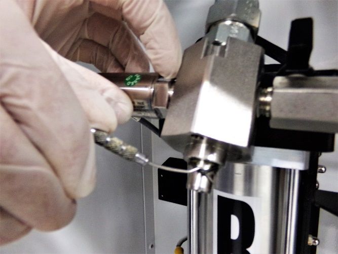
5. Push on the bottom of the cartridge until the material comes up into the nozzle as
shown below. This prevents introducing air into the material lines.
Figure 12: Prepare Cartridge for Loading
Revision A / January 2022 Page 18 of 32SCTP Operation Manual
6. Periodically make sure there is an O-ring installed on the metal feed tube and that the
O-ring is not worn.
• Leaked material on the outside of the canister indicates the O-ring has failed.
• Depending on the application, it is recommended that soft seals be replaced every
three (3) months. Refer to the How to Replace an O-ring section for instructions on
how to replace an O-ring.
Note: Soft seals are not under warranty.
7. Insert the new cartridge into the cartridge retainer.
• Make sure that the cartridge is installed in the correct servo cartridge pump (i.e.
Component A is installed in Pump A).
8. Swing the retainer closed and lock the cartridge retainer locking lever. Ensure that the
retainer is firmly locked in place and cannot move.
• If the sensor detects that the retainer is not closed, an error message will be
displayed: MATERIAL CARTRIDGE ERROR – CARTRIDGE UNLOCKED.
• To continue, readjust the locking lever and clear the error.
How to Bleed the Cartridge System
To maintain correct mixing, all air must be correctly bled from the system. Failure to purge
air bubbles may cause cartridge failure. This function allows the ram to bleed any air out of
the cartridge nozzle.
On initial startup or wetdown of a system, material must be dispensed through the hoses,
valves, and manifolds of the cartridge system, as follows:
In Continuous mode, select the Dispense button:
• Start at a low flow rate and press until material purges from the valve.
• Once there is material in the hoses, this procedure does not need to be repeated.
Revision A / January 2022 Page 19 of 32SCTP Operation Manual
To Bleed the System
1. Open the enclosure door and manually open the ball valve for the correct pump.
• Make sure the purge cup is correctly positioned at the outlet of the ball valve.
• While the ball valve is open, the ram will advance.
Figure 13: Opening the Ball Valve
2. Close the door.
3. Clear the door fault message.
4. Select Manual mode.
5. Select the Material button.
6. Press the Bleed button until material is dispensed into the purge cup.
Figure 14: Bleeding the Valve
Revision A / January 2022 Page 20 of 32SCTP Operation Manual
7. After the bleed is complete, open the enclosure door and close the ball valve.
8. Close the door and clear the door fault message.
Repeat the steps above for both pumps, as needed.
9. From the Setup menu:
• Set the rate (mL/min) for each pump (A and B).
• For modifications to the K-factor (calibration offset), contact Customer Service.
• Process PSI (min/max) – if out of range, an error message will be displayed.
10. Select the Ready button.
Preload Pressure
This function increases the pressure in the machine to the operating process pressure.
Refer to the Endurance manual for more information on this function.
• The preload pressure is adjustable. Refer to the Preload Pressure Adjustment
section of this manual.
Depressurization
When the machine is not in use it is necessary to relieve the pressure. If left under pressure
while not dispensing, thermal materials tend to separate, resulting in clogging or non-
uniform dispense. If the machine is idle for longer than a few hours, relieve the pressure on
the system in either of the following ways:
• Send ram position to the Refill position.
• Engage the Emergency Stop. Open door and keep the purge valve open until
pressure is drained. Close purge valve.
Note: Put a night cap on the valve when not in use.
Revision A / January 2022 Page 21 of 32SCTP Operation Manual
Pump Settings
Pump rates and preload pressure settings can be adjusted based on the material to be
dispensed. More information on these options can be found in the Endurance manual under
the Setup page.
Pump Rate Adjustment
To adjust the Pump Rate:
1. Select the Setup tab.
2. Select the desired Recipe from the list.
3. Select the button for Pump B or Pump A.
4. Adjust the pump Dispense Rate depending on the mix-ratio of the materials, as
necessary.
5. Select the Stop button to exit Setup mode and save the new values in the system’s
memory.
Preload Pressure Adjustment
To adjust the Preload Pressure:
1. Select the Setup tab.
2. Select the desired Recipe from the list.
3. Select the button for Pump B or Pump A.
4. Select the Preload tab.
5. Adjust the Process PSI, as necessary.
6. Press the Stop button to exit Setup mode and save the new values in the system’s
memory.
Revision A / January 2022 Page 22 of 32SCTP Operation Manual
Maintenance
This section contains general information on scheduling maintenance, O-ring replacement,
plumbing schematics and spare parts and accessories.
General Maintenance Schedule
Interval Action
• Examine and clean the cartridge connections, purge ports, and
two-part dispense valve nozzle.
• Make sure the mix ratio, flow rate, and the volume of
Daily component A and B materials are correct.
• Examine the motor cables and material supply hoses for signs
of wear, kinks or twists.
• Examine O-ring for signs of wear.
3-Months • Replace O-ring, as necessary.
How to Replace an O-ring
Depending on the application, it is recommended that soft seals be replaced every three (3)
months. To replace an O-ring:
1. Using a 4 mm hex key, unscrew the two (2) pressure transducer screws.
Figure 15: Unscrew Transducer Screws
2. Use an O-ring pick to remove the old O-ring.
Revision A / January 2022 Page 23 of 32SCTP Operation Manual
Figure 16: Removing the O-ring
3. Use an O-ring pick to replace the O-ring (Part Number #VLV-013V).
Figure 17: Replacing the O-ring
Revision A / January 2022 Page 24 of 32SCTP Operation Manual
Plumbing Schematic
Figure 18: Machine Plumbing Schematic
1 SERVO CARTRIDGE PUMP
2 TRANSDUCER CABLE
3 PRESSURE TRANSDUCER 0-500 PSI
4 BLEED VALVE AND PURGE POSITION
5 BALL VALVE AND PURGE POSITION
6 HOSE
7 DISPENSE VALVE
Revision A / January 2022 Page 25 of 32SCTP Operation Manual
Spare Parts and Accessories
PVA recommends having the following parts on hand for quick replacement.
Description Part number Notes
Cartridge sealing O-ring VLV-013V
Coupling P/N 612-10861-2 Comes with machine
Not a common replacement
part.
Figure 19: Spare Parts List
Contact PVA for information on replacement parts or to place an order.
Revision A / January 2022 Page 26 of 32SCTP Operation Manual
Technical Specifications
Description Part Number Notes
Shot Volume Single Component:
Minimum: 0.5 ml
Maximum: 946 ml
Dual Component:
Minimum: 1.0 ml
Maximum: 1892 ml
Flow Rate Single Component:
Minimum: 0.1 ml/min
Maximum: 300 ml/min
Dual Component:
Minimum: 1.2 ml/min
Maximum: 600 ml/min
Two-Component Mix 1:1 – 10:1
Ratio
Maximum Pressure 450 psi
Note: Maximum Dual Component Shot Volume and Maximum Dual Component Flow
Rate is dependent on material mix ratio.
Revision A / January 2022 Page 27 of 32SCTP Operation Manual
Troubleshooting
If dispense output is off ratio:
Check that correct desired flow rates are entered into the Endurance HMI.
• Confirm that both pumps are enabled.
• Verify that air is not trapped in the lines.
• Verify that the valve is not clogged or backed up.
• If the problem persists, contact PVA Customer Service.
If recurring over pressure faults occur:
• Confirm that the over pressure ranges set are reasonable.
• Some highly viscous fluids create significant back pressure when flowing. If
necessary, reduce rates to keep pressure within operable range.
Revision A / January 2022 Page 28 of 32SCTP Operation Manual
Drawings
Figure 20: Servo Cartridge Pump Dimensions
Revision A / January 2022 Page 29 of 32SCTP Operation Manual
Notes
Revision A / January 2022 Page 30 of 32SCTP Operation Manual
Table of Figures
Figure 1: Overview of SCTP Servo Cartridge Pump Components .................................................. 9
Figure 2: Endurance Machine with Servo Cartridge Pump Configuration ................................. 10
Figure 3: Airline Hookup and Electrical Hookup ................................................................................11
Figure 4: Machine with Rams in Home Position ............................................................................... 12
Figure 5: Perform Pre-Run Checks ..................................................................................................... 13
Figure 6: Open Valve (Left) and Closed Valve (Right) ..................................................................... 14
Figure 7: Manual Mode Screen ............................................................................................................. 15
Figure 8: Unloading Message ............................................................................................................... 16
Figure 9: Releasing a Cartridge ............................................................................................................ 16
Figure 10: Removing a Cartridge ......................................................................................................... 17
Figure 12: Remove Plug from New Cartridge .................................................................................... 18
Figure 13: Prepare Cartridge for Loading .......................................................................................... 18
Figure 14: Opening the Ball Valve ....................................................................................................... 20
Figure 15: Bleeding the Valve .............................................................................................................. 20
Figure 16: Unscrew Transducer Screws ........................................................................................... 23
Figure 17: Removing the O-ring .......................................................................................................... 24
Figure 18: Replacing the O-ring .......................................................................................................... 24
Figure 19: Machine Plumbing Schematic.......................................................................................... 25
Figure 20: Spare Parts List .................................................................................................................. 26
Figure 21: Servo Cartridge Pump Dimensions ................................................................................. 29
Revision A / January 2022 Page 31 of 32SCTP Operation Manual
PVA Warranty Policy
PVA warrants the enclosed product against defects in material or workmanship on all
components for one year from the date of shipment.
The warranty does not extend to components damaged due to misuse, negligence, or
installation and operation that are not in accordance with the recommended factory
instructions. Unauthorized repair or modification of the enclosed product, and/or the use
of spare parts not directly obtained from PVA (or from factory authorized dealers) will void
all warranties.
All PVA warranties extend only to the original purchaser. Third party warranty claims will
not be honored at any time.
Prior to returning a product for a warranty claim, a return authorization must be obtained
from PVA’s Technical Support department. Authorization will be issued either via the
telephone, facsimile, or in writing upon your request.
To qualify as a valid warranty claim, the defective product must be returned to the factory
during the warranty period. Upon return, PVA will repair (or replace) all components found
to be defective in material or workmanship.
(Retain this for your records)
Product Information:
PRODUCT: ______________________________
SERIAL NUMBER: ______________________________
DATE OF PURCHASE: ______________________________
Revision A / January 2022 Page 32 of 32You can also read