Section 8.3
       Tuck-in Device
(Electromagnetic valve drive)
←
→
Page content transcription
If your browser does not render page correctly, please read the page content below
Section 8.3
Tuck-in Device
(Electromagnetic valve drive)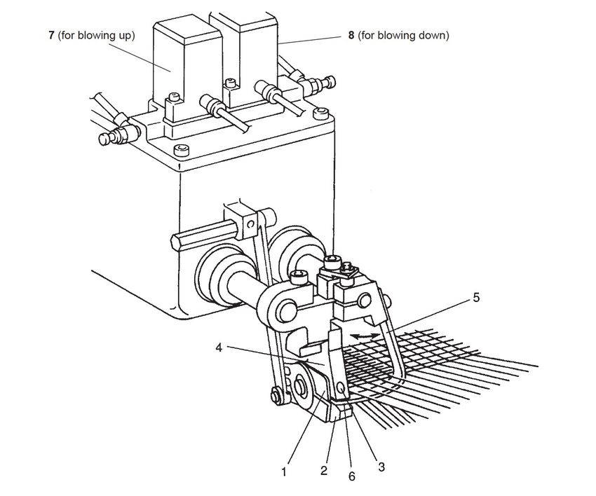
Contents
  8.3.1 Installation, Adjustment, and Weaving Technology …………………………………………………8.3-2
    [1] Installing the tucking needle ……………………………………………………………………………8.3-3
    [2] Right-to-left positioning of tuck-in devices ……………………………………………………………8.3-5
          [2.1]   Positioning the reed ……………………………………………………………………………8.3-5
          [2.2]   Adjusting the LH tuck-in device ………………………………………………………………8.3-5
          [2.3]   Adjusting the RH tuck-in device ………………………………………………………………8.3-6
    [3] Adjusting the tuck-in device on the weaving machine ………………………………………………8.3-7
    [4] Cutters ……………………………………………………………………………………………………8.3-8
    [5] Intake nozzle (at the RH tuck-in device) ……………………………………………………………8.3-10
    [6] Positioning the tuck-in devices, front-to-rear and up-down ………………………………………8.3-11
        [6.1] Positioning the tucking needle ………………………………………………………………8.3-12
    [7] Blow-out timing and air pressure ……………………………………………………………………8.3-13
    [8] Shed size and shed close timing ……………………………………………………………………8.3-14
    [9] Main nozzle cutting blow ……………………………………………………………………………8.3-15
    [10] Checking the piping and wiring ……………………………………………………………………8.3-15
    [11] Cleaning the tuck-in devices ………………………………………………………………………8.3-16
  8.3.2   Basic Rules in Forming Selvages (Weaving Technology) ………………………………………8.3-17
    [1]   Know-how for forming selvages ……………………………………………………………………8.3-17
    [2]   Selvage construction samples ………………………………………………………………………8.3-19
  8.3.3   Troubleshooting for Tuck-in Miss ……………………………………………………………………8.3-21
    [1]   At LH tuck-in device …………………………………………………………………………………8.3-21
    [2]   At RH tuck-in device …………………………………………………………………………………8.3-28
  8.3.4 Grinding of Tuck-in Device RH Cutter ………………………………………………………………8.3-31
    [1] Grinding procedure ……………………………………………………………………………………8.3-31
  8.3.5 Middle Tuck-in Device ………………………………………………………………………………8.3-33
    [1]   Threading warps through the reed …………………………………………………………………8.3-33
    [2]   Positioning the tucker base, front-to-rear ……………………………………………………………8.3-33
    [3]   Positioning the temples, right-to-left …………………………………………………………………8.3-34
    [4]   Positioning the middle tuck-in device ………………………………………………………………8.3-35
  8.3.6   Replacement of Oil Seal    ……………………………………………………………………………8.3-36
    [1]   Procedure for Tucker Oil SealRemoval ……………………………………………………………8.3-39

8.3-1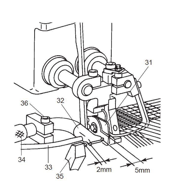
Tuck-in Device (Electromagnetic valve drive)

The tuck-in device produces tucked-in selvages according to the following procedure:

  (1)   Cutter 1 trims an inserted weft yarn to a maximum of 14-15 mm outside the cloth edge.
  (2)   Lower nozzle 2 blows up the end of the trimmed weft into catch hole 3.
  (3)   Upper nozzle 4 threads the weft end through long hole 6 provided in the top of tucking needle 5.
  (4)   As tucking needle 5 moves to the right and left, the weft end will be pulled back into the woven
        cloth.

Blowing up and down the end of the trimmed weft is controlled by electromagnetic valves 7 and 8. You
may set the blowing-up and -down timings on the function panel.

                                                                                                         8.3-1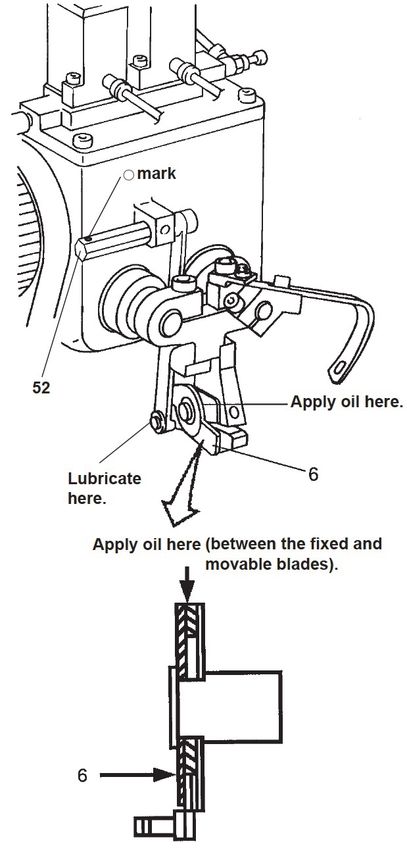
8.3.1 Installation, Adjustment, and Weaving Technology

  8.3.1 Installation, Adjustment, and Weaving
        Technology

                                                         The driver section of the tuck-in device, in which
                                                         the gears are rotating, is covered with safety
                                                         covers A and B (as shown at left). NEVER run the
                                                         machine without those safety covers or touch the
                                                         driver section.
                                                         Be sure to lock the machine with the emergency
                                                         stop button except for jobs requiring manual
                                                         rotation.

                                                          Before the start of new fabric weaving:
                                                          ・Grasp the cover factor of fabric to be woven.
                                                           (The standard cover factor is "31" when the reed
                                                             space is 190 cm. Use this number as a guide for
                                                             checking the weaving difficulty and availabilit
                                                             y.)
                                                          ・Determine the selvage structure.

8.3-2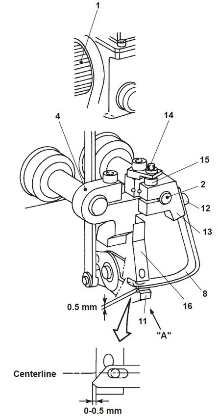
8.3.1 Installation, Adjustment, and Weaving Technology

[1] Installing the tucking needle
                                    The following steps (1) through (8) are a basic
                                    adjustment procedure, so proceed step by step. It
                                    is recommended that you take off the tuck-in
                                    device from the machine before starting this job.

                                    NOTE: This machine leaves TOYOTA after
                                          undergoing this adjustment, but check
                                           whether the tucking needle is correctly
                                           mounted.

                                    (1) Before installing tucking needle 8, check that
                                        the section which slides through warps,
                                        particularly its top end, is sufficiently
                                        polished and has no scratches or burr.
                                    (2) Turn the driving gear 1 to move scissors shaft
                                        2 to the forefront position.
                                    (3) Remove stopper 14, or turn it to avoid bolt 15.
                                    (4) Vertically adjust tucking needle 8 by turning
                                        bolt 12 to provide a clearance of 0.5 mm
                                        between tucking needle 8 and lower nozzle
                                        support 11.
                                    (5) By turning bolt 15, adjust tucking needle 8 so
                                        that the centerline of its long hole becomes
                                        aligned with that of the hole of lower nozzle
                                        support 11, as shown at left.
                                        Check the alignment of these holes by
                                        viewing from the direction of arrow "A" (from
                                        the bottom).
                                    (6) Secure needle holder 13 with bolt 15 so that
                                        the end of tucking needle 8 protrudes from
                                        the side of lower nozzle support 11 by 0-0.5
                                        mm.

                                                                                      8.3-3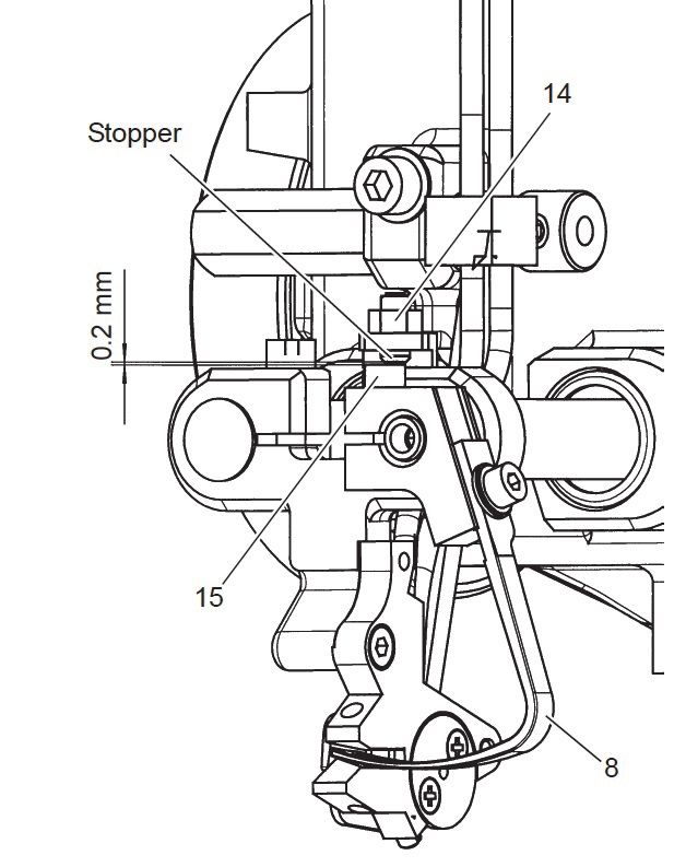
8.3.1 Installation, Adjustment, and Weaving Technology

                                                         (7) Install stopper bolt 14, and adjust the gap
                                                             between bolt 15 and the stopper to 0.2 mm at
                                                             the maximum stroke position of needle 8.

                                                         (8) Turn driving gear 1 to retract scissors shaft 2
                                                             fully. Then, check that the gap between
                                                             tuckin housing 3 and clamp 4 comes to 3 mm.

                                                             NOTE: Lubricate the surface of scissors shaft
                                                                   2 as follows:
                                                               ・Lubricating intervals: Once/day
                                                               ・Lubrication tools: Oiler (Tool No. 695)
                                                               ・Lubricant: Lubricant A (Refer to Chapter
                                                                           M, Section M.3.)

8.3-4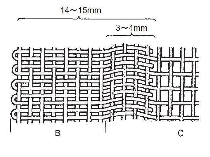
8.3.1 Installation, Adjustment, and Weaving Technology

[2] Right-to-left positioning of tuck-in devices
[2.1] Positioning the reed
                                         Position the reed so that the distance "a" from
                                         its 1st dent to the inside of the side frame comes
                                         to 212 mm.
                                         For fabric style change or new fabric weaving
                                         work, it is not necessary to remove the LH
                                         tuck-in device.
                                         If any problem occurs so that the LH tuck-in
                                         device should be removed, be sure to adjust it
                                         according to the procedure given in [2.2].

[2.2] Adjusting the LH tuck-in device
                                         (1) Set the crank angle at 180°.
                                         (2) Loosen coupling 29 of gear 23 to disengage
                                             gear 23 from idle gear 22.
                                         (3) Turn the driving gear 1 to retract the
                                              scissors shaft fully. With the scissors shaft
                                              being retracted, place the tuck-in device on
                                             tucker support 38.
                                         (4) Taking care not to hit the tuck-in device
                                              against the reed, set the crank angle at
                                              approx. 350°.
                                         (5) Tighten screw 25 on tucker support 38,
                                              then position the LH tucker stand so that
                                              the clearance between nozzle support 10
                                              and the 1st dent of the reed comes to 0.5
                                              mm. Make sure that the reed is parallel
                                              with the temple cap.
                                         (6) Engage gear 23 with idle gear 22 and
                                              tighten coupling 29.
                                              NOTE: The backlash between gear 23 and
                                                    idle gear 22 should be 0.1 to 0.2 mm.
                                                * Checking the position of temple
                                                   Run the machine and check that the
                                                   end of temple 53 is aligned with the
                                                   edge of fabric (at A in figure at left).
                                                   If the alignment is off, adjust the
                                                   inclination of the temple, the height of
                                                   the temple cap, or the reed position.
                                                   If the fabric edge works out of the
                                                   temple, warp float will result at the left
                                                   edge of the fabric. If the fabric edge
                                                   does not reach the temple, a tuck-in
                                                   miss will result.

                                                                                          8.3-5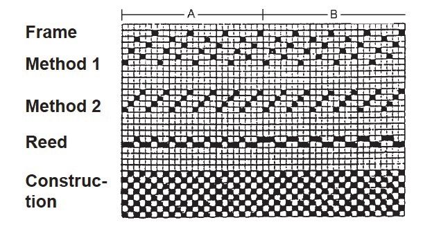
8.3.1 Installation, Adjustment, and Weaving Technology

[2.3] Adjusting the RH tuck-in device
                                                         (1) Set the crank angle at 180°.
                                                         (2) Loosen coupling 29 of gear 23 to disengage
                                                             gear 23 from idle gear 22.
                                                         (3) Turn the driving gear 1 to retract the
                                                             scissors shaft fully. With the scissors shaft
                                                             being retracted, place the tuck-in device on
                                                             tucker support 38.
                                                         (4) Taking care not to hit the tuck-in device
                                                             against the reed, set the crank angle at
                                                             approx. 350°.
                                                         (5) Position the RH tucker stand so that
                                                             clearance "b" between nozzle support 10
                                                             and the right end of the drawing-in width
                                                             comes to 0.5-1.0 mm and that the right end
                                                             of the drawing-in width becomes aligned
                                                             with the rightmost ring of temple 54. Make
                                                             sure that the reed is parallel with the
                                                             temple cap.
                                                         (6) Engage gear 23 with idle gear 22 and
                                                             tighten coupling 29.
                                                             NOTE: The backlash between gear 23 and
                                                                   idle gear 22 should be 0.1 to 0.2 mm.
                                                               * Checking the position of temple
                                                                 Run the machine and check that the
                                                                 end of temple 53 is aligned with the
                                                                 edge of fabric (at A in figure at left).
                                                                 If the alignment is off, adjust the
                                                                 temple, the height of the temple cap, or
                                                                 the position of the tuck-in device.
                                                                 If the fabric edge works out of the
                                                                 temple, warp float will result at the left
                                                                 edge of the fabric. If the fabric edge
                                                                 does not reach the temple, a tuck-in
                                                                 miss will result.

                                                             NOTE: If the machine is not equipped with
                                                                   the electric centralized lubrication
                                                                    system, apply grease to the
                                                                    intermediate bearings of driving
                                                                  shaft 28 as specified below.
                                                               ・Lubricating intervals: Every warp
                                                                                       beam change (at
                                                                                          least once/
                                                                                          month)
                                                               ・Lubrication tools: Grease gun

8.3-6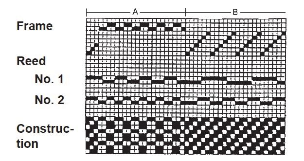
8.3.1 Installation, Adjustment, and Weaving Technology

                                        ・Lubricant: Lubricant D (Refer to
                                                    Chapter M, Section M.3.)

[3] Adjusting the tuck-in device on the weaving machine
                                (1) Fix shaft 52 with a 10-mm box-end wrench so
                                    that the shaft will not rotate, then turn
                                    coupling 30 towards you with a 30-mm width
                                    spanner in order to fully loosen the taper
                                    bushing inside the coupling. This way,
                                    driving gear 1 and shaft 52 are released.
                                (2) Set the crank angle at the timing where
                                    scissors shaft 2 starts forwarding. (The
                                    standard setting is 10°.)

                                    NOTE: The possible setting range is from 0°
                                          to 15°. If you delay the timing,
                                           however, check that the TAPO’s blow
                                           duct and the reed do not interfere with
                                           the needle holder.
                                (3) Rotate shaft 52 in the forward direction up to
                                    the point where scissors shaft 2 starts
                                    forwarding towards the reed, and then
                                    tighten coupling 30 to secure driving gear 1 to
                                    shaft 52. (Tightening torque: 30 N•m (300
                                    kgf•cm))
                                (4) Manually operate the machine to check that a
                                    sequence of the device operation produces no
                                    problem.

                                    NOTE: Apply grease to the engaged points
                                          between gears 1, 22, and 23 as
                                           specified below.
                                      ・Lubricating intervals: Once/month
                                      ・Lubrication tools: Brush
                                      ・Lubricant: Lubricant D (Refer to Chapter
                                                  M, Section M.3.)

                                                                                 8.3-7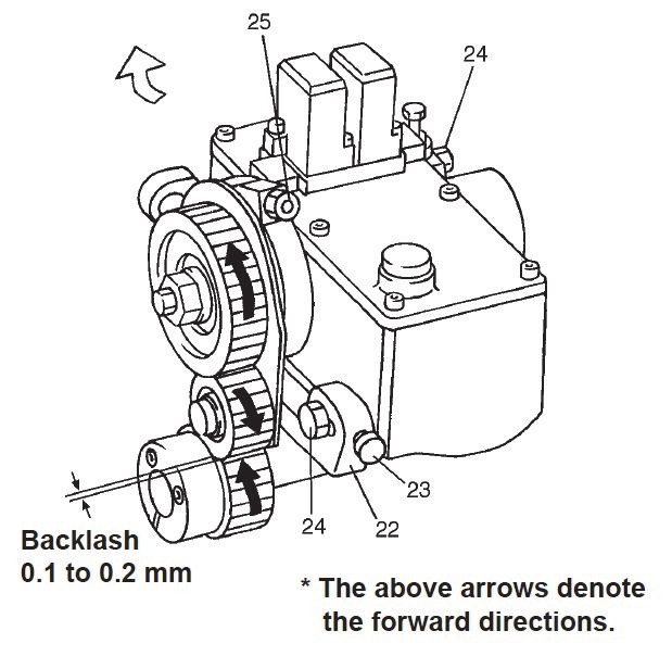
8.3.1 Installation, Adjustment, and Weaving Technology

[4] Cutters
                                                         To cut a weft, the LH tuck-in device uses the weft
                                                         cutter (LH cutter) mounted on the machine and
                                                         the RH tuck-in device uses its cutter (movable
                                                         blade).

                                                         (1) LH cutter for LH tuck-in device
                                                             Set LH cutter 51 so that it cuts a weft when
                                                             the crank angle is 10°. (If necessary, you may
                                                             modify the weft cutting timing to 340°-20°.)
                                                             Check with a stroboscope that a weft stably
                                                             enters the upper hole in nozzle support 10
                                                             after being cut.
                                                             NOTE: The LH tuck-in length may be
                                                                   changed by adjusting the cutter
                                                                       bracket position or modifying the
                                                                       cutter timing. For the adjustment
                                                                       procedure of the LH cutter, refer to
                                                                       Chapter 3, Section 3.5A.1.
                                                         (2) Tuck-in cutter on RH tuck-in device
                                                             The RH tuck-in device has movable blade 6
                                                             which cuts a weft when the crank angle is
                                                             95°- 100°.
                                                             Check with a stroboscope that movable blade
                                                             6 cuts a weft when the weft reaches right
                                                             above the lower hole. To adjust the cutting
                                                             timing, use eccentric pin 52. (The o-marked
                                                             side is an eccentric side which should face up
                                                             as standard.)
                                                             NOTE: The RH tuck-in length cannot be
                                                                   changed.

                                                             NOTES:
                                                             1.Apply oil to the cutter lever bearing and
                                                                   cutter shaft as specified below.
                                                               ・Lubricating intervals: Once/day
                                                               ・Lubrication tools: Oiler (Tool No. 695)
                                                                                       (Refer to Chapter M,
                                                                                       Section M.3.)
                                                               ・Lubricant: Lubricant A (Refer to Chapter
                                                                           M, Section M.3.)
                                                               ・When the fixed and movable blades
                                                                overlap by 1 mm at their tips (closed
                                                                    position), apply oil to the contact point of
                                                                    those blades until the bearing is fully
                                                                    lubricated.

8.3-8
8.3.1 Installation, Adjustment, and Weaving Technology
2.When using the spare parts or supplies for
the RH cutter, dip them in oil (Lubricant
B specified in Chapter M, Section M.3) for
more than 24 hours but less than a week
before use.
3.Do not apply oil excessively; otherwise,
the woven cloth may be stained.
8.3-98.3.1 Installation, Adjustment, and Weaving Technology
[5] Intake nozzle (at the RH tuck-in device)
When no waste selvage is to be produced, the
tuck-in device requires intake nozzle 32 to take in
waste thread resulting from the cutting of weft.
■ Installation procedure
(1) Install intake nozzle 32 approx. 5 mm apart
from end 31 of the cutter.
(2) Connect air pressure pipe 33 with the suction
valve; connect exhaust pipe 34 to the waste
thread box.
(3) Front-to-read positioning:
Set the crank angle at 0°, then adjust intake
nozzle 32 so that the distance from its tip to
the rear side of reed 37 comes to 7 mm and
that the gap between intake nozzle 32 and
weft feeler 35 comes to approx. 2 mm. Secure
intake nozzle 32 with bolt 36.
NOTE: When shifting the tuck-in device, take
care not to hit intake nozzle 32 against
reed 37 and weft feelers 35.
(4) Set or modify the intake nozzle timing on the
function panel. The standard timing is 330°
to 130°.
Also, adjust the opening of the intake throttle
valves. The standard valve opening can be
obtained by rotating each of them by 8 turns
from the fully-closed position.
Refer to [ 7 ].
(5) Run the weaving machine in practice and
check with a stroboscope that a weft is taken
into the intake nozzle.
8.3-108.3.1 Installation, Adjustment, and Weaving Technology
[6] Positioning the tuck-in devices, front-to-rear and up-down
It is necessary to adjust the tuck-in device to the
front or rear and up or down, since the looseness
of warps and cloth fell height differ depending
upon the texture types.
(1) Set the crank angle at approx. 180°.
(2) Loosen bolt 21 on idle gear holder 43 to
increase the backlash between idle gear 22
and gear 23.
(3) Loosen bolt 25 which secures the tuck-in
device to tucker support 38.
(4) Adjust the tuck-in device to front-to-rear and
up-down by turning bolt 50 and bolt 49,
respectively, so that the tucking needle comes
to the place as specified in steps (1) and (2) in
[6.1] on the next page.
(5) After positioning, tighten bolt 25.
(6) Tighten bolt 21 on idle gear holder 43 to
eliminate the backlash between idle gear 22
and gear 23 to 0.1-0.2 mm.
NOTE: After making front-to-rear or up-down
adjustment of the tuck-in device, be
sure to check the backlash between
idle gear 22 and gear 23.
(7) Turn the hand wheel manually to check that:
・the timing where the scissors shaft starts
forwarding is 10° (The possible setting
range is from 0° to 15°.) and
・the needle holder does not interfere with
the reed.
8.3-118.3.1 Installation, Adjustment, and Weaving Technology
[6.1] Positioning the tucking needle
Set the crank angle at approx. 270°, then make
the adjustment below at each of the RH and LH
tuck-in devices.
(1) Front-to-rear positioning
Adjust tucking needle 8 so that the
distance from needle 8 to the cloth fell
comes to a maximum of 1 mm.
(2) Up-down positioning
Adjust tucking needle 8 to place it as near
the lower warps as possible.
After the up-down adjustment, make sure
that the tucking needle does not come into
strong contact with the lower warps or
break through them during weaving.
(3) Operational check
To confirm that tucking needle 8 is
correctly adjusted, make an operational
check.
Weave by a few meters and check that the
tucking needle enters through the upper
warps 20 to 30 mm* from upper nozzle
support 10.
(*This distance will vary depending upon
the change of the shedding angle.)
8.3-128.3.1 Installation, Adjustment, and Weaving Technology
[7] Blow-out timing and air pressure
The air stream from lower nozzle 11 keeps a weft
end in the upper catch hole.
The moment tucking needle 8 reaches the fully
retracted position, the upper nozzle blows air to
thread the weft end through the long hole
provided in the tucking needle, into the lower
catch hole.
You may modify the air blow-out timings in the
above sequences on the window called up by
touching MAP–TUCKER (on FUNCTION panel).
The timings shown at left are default and
standard values. However, they are not available
for the initial condition setting (ICS) function.
If you use middle tuckers, enter the number of
middle tuckers into CENTER TUCKER.
Setting items for blow-out timings appears.
Set TUCKER to Unused if no tuckers are used.
Setting this item to Unused stops valve output in
order to save air consumption.
8.3-138.3.1 Installation, Adjustment, and Weaving Technology
All of the air to be used for blowing up or down the
end of the trimmed weft and for taking waste
thread into the intake nozzle are supplied by the
sub-end tank. The air pressure of the sub-end
tank should be set at the same level as that of the
sub tank or slightly higher. Note that a minimum
of 0.35 MPa (3.5 kg/cm2G) is required.
The table below lists the standard openings of
throttle valves 7 and 8 provided at the entrance of
each valve. It is necessary to make some fine
adjustments of those valves while keeping an eye
on the posture of blowing weft with a stroboscope
so that the weft becomes tense in a stabilized state.
Electromagnetic valves Opening of throttle valves
Rotate the valves by 8
For tucker suction (for
turns from the
the intake nozzle)
fully-closed position.
For tucker blow-up Rotate the valves by 4
turns from the
For tucker blow-down
fully-closed position.
[8] Shed size and shed close timing
(1) Shed size
The standard shed open angle is 32°.
For some of those machines equipped with a
dobby, the shed open angle may be limited to
30° depending upon the number of heald
frames to be used and the machine speed
(rpm).
(2) Shed close timing
The standard shed close timing is 280°. In
case of plain weaving with phase shift, set the
earlier timing at 280°.
8.3-148.3.1 Installation, Adjustment, and Weaving Technology
[9] Main nozzle cutting blow
Set the blow start angle 10° earlier than the weft
cutting timing (at the LH tuck-in device) and set
the shed size at 30° to 40°.
[10] Checking the piping and wiring
Check the piping. When viewed from the front of
the machine, the electromagnetic valve for
up-blow air is provided at the right-hand side;
that for downblow air is at the left-hand side.
Check the wiring by referring to the ID codes
marked on the tubes listed below.
ID codes marked on
Electromagnetic valves
tubes
For tucker suction TUCKER SUC
For tucker
BLW RHA
blow-up
RH
For tucker
BLW RHB
blow-down
For tucker
BLW MIDA
blow-up
MID*
For tucker
BLW MIDB
blow-down
For tucker
BLW LHA
blow-up
LH
For tucker
BLW LHB
blow-down
* MID: Middle tuck-in device
To check that the piping and wiring are correct,
call up the screen shown at left by touching
MANUAL and make the comparison check
between switches and their functions.
8.3-158.3.1 Installation, Adjustment, and Weaving Technology
[11] Cleaning the tuck-in devices
Clean the tuck-in devices once a day. If fly or
fleece accumulates particularly on the scissors
shaft, not only the woven fabric will be stained
but also the oil seal will be worn resulting in oil
leakage.
8.3-168.3.2 Basic Rules in Forming Selvages (Weaving Technology)
8.3.2 Basic Rules in Forming Selvages (Weaving
Technology)
Ends of the turned-back wefts should be drawn
into the ground construction by at least 3-4 mm,
except for selvage warps which are crossed with
wefts every pitch.
Such a construction is capable of catching weft
ends even if selvage warps are not crossed with
wefts.
If the yarn density in the above 3-4 mm range is
too high, thin out the warps.
A: Selvage
B: Ground
[1] Know-how for forming selvages
The tuck-in device produces tuck-in selvages with
a maximum of 14-15 mm width.
The weft density in the tuck-in selvages is double
in the ground, so that troubles due to thick
selvages may occur in the subsequent processes.
To prevent such problems, use any of the
following solutions:
(1) Lower the warp density of the selvage to less
than that of the ground.
(2) Make the selvage construction coarser than
that of the ground.
(3) Use finer yarns for the selvages than those
for the ground.
Use your experience to make a selection from the
solutions above according to the construction,
yarn type, and yarn count.
One of the most important keys is to make a test
weaving up to the final process when a new style
construction is applied and to check the tuck-in
selvages for no involved problems before
proceeding to the practical production.
What follows are basic rules for drawing warps
through reeds and the standard selvage
constructions.
8.3-178.3.2 Basic Rules in Forming Selvages (Weaving Technology)
a. Apply at least one pattern that crosses a warp
with a weft every pitch, in the edges of tuck-in
selvages.
Generally, the ground construction is used as
the pattern.
b. Make the number of warps per reed’s dent in
the edges of tuck-in selvages greater than the
number of warps drawn inside the selvages.
Generally, the same number of warps per
dent for the ground is applied.
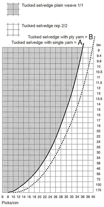
■ Square sett
Fabrics with a warp and weft density of typically
20/16 threads/cm and a 25 tex × 2 yarn in warp
and weft, or 19/18 threads/cm and an 18 tex × 2
yarn, can be woven with a selvedge in plain weave
1/1, whereby the warp ends in the selvedge may
be thinned by up to 16%. Denser fabrics, however,
need a looser selvedge weave such as rep 2/2 (see
figure in [ 2 ] (2)). If a plain weave 1/1 selvedge
results in too tight interlacing, while rep 2/2 gives
too loose an appearance, the selvedge may also be
woven in rep 2/1 (see figure in [ 2 ] (3)).
The adjacent diagram shows options for forming a
plain weave 1/1 or rep 2/2 selvedge for plain
weave fabrics with square sett. The solid curve A
is based on the assumption of single yarn in the
selvedge, i.e. the same yarn as in the body of the
fabric. For fabrics of manmade spun yarns a 10%
lower weft density than that shown must be
reckoned with. If ply yarn instead of singles is
used for the selvedge of cotton or manmade spun
yarn fabrics, the weft density may be increased by
up to 15% depending on the quality of the ply
yarn. The values are indicated by the broken line
B. Thus for example a renforce with 30/30
threads/cm, 20 tex/20 tex needs a selvedge of
combed cotton ply yarn 12 tex × 2 to 10 tex × 2.
8.3-188.3.2 Basic Rules in Forming Selvages (Weaving Technology)
[2] Selvage construction samples
(1) Poplin
Ground B: 1/1
Selvage A: 1/1
(2) Cretonne, sheeting, and worsted fabric
Ground B: 1/1
Selvage A: 2/2
(3) Thin worsted fabric
Ground B: 1/1
Selvage A: 2/1 + 1/2
(4) Cotton and cotton-combined twill fabric
(high-density)
Ground B: 3/1
Selvage A: 2/2
(5) Cotton and cotton-combined twill fabric
(lowdensity)
Ground B: 3/1
Selvage A: 3/1 + 1/3
8.3-198.3.2 Basic Rules in Forming Selvages (Weaving Technology)
(6) Thick cotton fabric
Ground B: 3/1
Selvage A: 3/1 + 1/3
(7) Cotton twill fabric
Ground B: 2/2
Selvage A: 2/2
(8) Cotton, worsted fabric, and panama
Ground B: 3/1
Selvage A: 3/1
(9) Cotton fabric, 2/1 twill (high-density)
Ground B: 2/1
Selvage A: 3/3
(10) Worsted fabric (high weft density)
Ground B: 2/1
Selvage A: 2/1 + 1/2
8.3-208.3.3 Troubleshooting for Tuck-in Miss
8.3.3 Troubleshooting for Tuck-in Miss
This section lists several tuck-in miss samples at
each of the LH and RH tuck-in devices. If a
tuck-in miss occurs, take the necessary action by
referring to these samples.
A: Tuck-in miss B: Selvage C: Ground
[1] At LH tuck-in device
LH trouble 1: A tuck-in miss occurs at almost
every pick (resulting in a fringed
edge).
■ Probable causes
The tuck-in device malfunctions (e.g.
blowing-up failure at the nozzle support).
■ Troubleshooting
(1) Check that the piping and wiring are
correct. (Refer to Section 8.3.1, [ 10 ].)
(2) Check the air pressure and the
blowing-out timings. (Refer to Section
8.3.1, [ 7 ].)
(3) Check each part of the tuck-in devices
for failure or damage.
[Example]
・Replace the nozzle support.
・Replace the tuck-in device proper.
8.3-218.3.3 Troubleshooting for Tuck-in Miss
LH trouble 2: A tuck-in miss occurs frequently
(resulting in a fringed edge).
■ Probable causes
The weaving machine or the tack-in device
malfunctions (e.g. blowing-up failure at the
nozzle support).
■ Troubleshooting
(1) Check the cutter timing with a
stroboscope.
After a weft is cut, check that the yarn is
led into the upper section of the nozzle
support.
The standard cutting timing is 10°.
If a tuck-in miss persists, modify the
cutting timing within the range from
340° to 20°.
(2) Check the air pressure and the
blowing-out timing at the nozzle support.
After a weft is cut, check that the yarn is
led into the upper section of the nozzle
support.
(3) Check the opening of throttle valves 7
and 8.
The standard valve opening can be
obtained by rotating the valve by 4 turns.
If a tuck-in miss persists, increase or
decrease the valve opening.
(4) Check whether the nozzle support itself
is defective by replacing it with a normal
nozzle support.
8.3-228.3.3 Troubleshooting for Tuck-in Miss
(5) Check the front-to-rear position of the tuck-in
device.
The distance from the tucking needle 8 to the
cloth fell should be 0-1 mm.
If the distance is longer, the end of a weft
blown up by upper nozzle 4 cannot be
threaded through the long hole provided in
the top of tucking needle 8. Also, the
tucked-in weft easily slips off.
When the machine is in operation, check with
a stroboscope that a weft stands by, with its
end 2-3 mm above the catch hole provided in
the upper nozzle support.
(6) Check the height of the tuck-in device.
The center of nozzle support 4 should be
almost flush with the end of the cloth.
・If the tuck-in device is positioned at the
higher place (A in the figure at left), the
end of a standing-by weft does not come up
by 2-3 mm so that tucking-in operation
becomes unstable.
・If the tuck-in device is positioned at the
lower place (B in the figure at left), warp
float will result.
NOTE: Warp float will appear on the back of
the cloth. To prevent the detection of
the warp float from becoming late,
therefore, do some actual weaving (by
several cm) and make visual checking
if you adjust the height of the tuck-in
device or make the initial condition
setting (ICS).
8.3-238.3.3 Troubleshooting for Tuck-in Miss
(7) Check the installation position of the reed.
The edge of cloth should be aligned with the
end of the temple.
If the cloth edge does not reach the end of the
temple, a standing-by weft becomes unstable.
If a tuck-in miss persists after correcting the
position of the reed, adjust the inclination of
temple 9 or the height of the temple cap.
(8) Check that the end of tucking needle 8
protrudes from the side of nozzle support 4 by
0-0.5 mm.
If tucking needle 8 is not correctly positioned,
the blown weft will not be threaded through
needle 8 smoothly.
For the adjustment procedure, refer to
Section 8.3.1, [ 1 ].
8.3-248.3.3 Troubleshooting for Tuck-in Miss
LH trouble 3: A tuck-in miss occurs sometime
(less than 4-5 times per meter).
■ Probable causes
Same as "LH trouble 2."
■ Troubleshooting
(1) Check that the ends of the turned-back
wefts are drawn into the selvage and
ground as shown at left.
Tuck-in selvages are 14-15 mm in width.
Therefore, determine the number of
selvage yarns so that the ends of the
turned-back wefts will be drawn into the
selvage by 11 mm and further into the
ground C by 3-4 mm.
If the width of tuck-in wefts is less than
14 mm, adjust the position of the cutter
bracket.
(2) Check the drawing-in style through the
leftmost heald and the reed.
The drawing-in style differs depending
upon the fabric construction, yarn
number count, and machine speed. Find
the drawing-in style suited to the
required fabric.
For the basic drawing-in styles, refer to
Section 8.3.2.
(3) Check the above LH troubles 1 and 2
again.
8.3-258.3.3 Troubleshooting for Tuck-in Miss
LH trouble 4: Loosened weft loops result from
incomplete tucking-in.
■ Probable causes
The tuck-in operation following blowing-up
at the nozzle support is faulty.
■ Troubleshooting
(1) Check the shed close timing of the
machine.
The standard timing is 280°. For plain
weaving with phase shift, set 280° for
the earlier phase.
If the shed close timing is excessively
delayed or advanced, a weft threaded
through the tucking needle may work
out halfway due to either lack or excess
of weft pressure, respectively.
(2) Check that a weft is pulled by the corner
of the long hole provided in the tucking
needle 8 (see the figure shown at left).
If a weft is pulled by another section of
the long hole, there may be scratches on
the inside of the hole. Smooth it with
sandpaper #600 or #1000.
(3) Check that the front-to-rear positioning
is correct.
The distance from the cloth fell to the
tucking needle should be 0-1 mm when
the crank angle is 270°.
8.3-268.3.3 Troubleshooting for Tuck-in Miss
LH trouble 5: Every end of tucked-in wefts
emerges out of the cloth surface.
■ Probable causes
The insertion position of tucking needle 8
into warps is wrong.
■ Troubleshooting
(1) Check the tuck-in width.
The standard width is 14-15 mm.
(2) Check the entry position of tucking
needle 8 into warps. If it is wrong, check
the following:
・Heights of tucking needle 8 and nozzle
support 4
・Height of heald frame
・Shed size (The standard shed opening
is 32°.)
・Shed close timing (should not be
delayed)
8.3-278.3.3 Troubleshooting for Tuck-in Miss
[2] At RH tuck-in device
RH trouble 1: A tuck-in miss occurs at almost
every pick (resulting in a
fringededge).
■ Probable causes
The tuck-in device malfunctions (e.g.
blowing-up failure at the nozzle support).
■ Troubleshooting
Refer to [ 1 ], "LH trouble 1: A tuck-in miss
occurs at almost every pick (resulting in a
fringed edge)."
RH trouble 2: A tuck-in miss occurs frequently
(resulting in a bearded edge).
■ Probable causes
The weaving machine or the tack-in device
malfunctions (e.g. blowing-up failure at the
nozzle support).
■ Troubleshooting
Check the cutter timing with a stroboscope.
The standard cutting timing is 95°-100°.
Refer to [ 1 ], "LH trouble 2: A tuck-in miss
occurs frequently (resulting in a fringed edge)."
8.3-288.3.3 Troubleshooting for Tuck-in Miss
RH trouble 3: A tuck-in miss occurs sometime
(less than 4-5 times per meter).
■ Probable causes
Same as “RH trouble 2.”
■ Troubleshooting
Refer to [ 1 ], "LH trouble 3: A tuck-in miss
occurs sometime (less than 4-5 times per
meter)."
RH trouble 4: A tuck-in miss occurs or the
tucked-in selvage is too wide.
■ Probable causes
The cutter or suction-related components are
faulty.
■ Troubleshooting
(1) Check that a weft is led to nearly the
center of the opened cutter and trimmed
by the cutter.
(2) Check that the cutter is sharp.
(3) Check the cutter timing. (It should be
95° to 100°.)
(4) Check that a weft is pulled into the
suction pipe. If not, check the following:
・Height of the suction pipe
・Air pressure of the suction pipe
(should not too low)
・Outlet of the suction pipe not clogged
with waste yarns
For the adjustment of the suction pipe,
refer to Section 8.3.1, "[ 5 ] Intake
nozzle (at the RH tuck-in device)."
8.3-298.3.3 Troubleshooting for Tuck-in Miss
RH trouble 5: Loosened weft loops result from
incomplete tucking-in.
■ Probable causes
The tuck-in operation following blowing-up
at the nozzle support is faulty.
■ Troubleshooting
Refer to [ 1 ], "LH trouble 4: Loosened weft
loops result from incomplete tucking-in."
RH trouble 6: Every end of tucked-in wefts
emerges out of the cloth surface.
■ Probable causes
The insertion position of tucking needle 8
into warps is wrong.
■ Troubleshooting
Refer to [ 1 ], "LH trouble 5: Every end of
tucked-in wefts emerges out of the cloth
surface."
8.3-308.3.4 Grinding of Tuck-in Device RH Cutter
8.3.4 Grinding of Tuck-in Device RH Cutter
If the RH cutter of the tuck-in device becomes
dull, you should grind the cutter blades.
Note that any of the following cutters should be
replaced with a new one:
・Cutters whose blades are broken or damaged
・Cutters whose blades will be opened by a force
of less than 5.4 N (550 g) when pulled down
with the spring balance 1 as shown at left
[1] Grinding procedure
(1) Clamp cutter grinder body 1 (J8213-15010-
00) with a vice.
(2) Fit positioning plate 3 on clamper plate 4 as
shown at left, then secure positioning plate 3
with screw 2.
(3) Fully open the RH cutter 7 of the tuck-in
device and secure it with clamper plate 4 by
tightening bolt 5 so that the full length of the
blade edge comes into contact with
positioning plate 3.
(4) Loosen screw 2 and turn positioning plate 3
in the direction of the arrow shown at left.
Tighten screw 2.
8.3-318.3.4 Grinding of Tuck-in Device RH Cutter
(5) Fully pull up support 9 and secure it with bolt
10 at the lowermost position of the long hole
provided in support 9, for grinding at the 25°
clearance angle.
(6) To grind the cutter blade, move coarse
diamond file 8 (J8213-16010-00) in the
direction of the arrow shown at left in such a
way that one pass of the file covers the entire
edge of the blade, while immersing the file
repeatedly in benzine.
Repeat this process until the full length of the
blade is ground.
(7) Loosen bolt 10 and pull up support 9 until its
marker is aligned with the top of the cutter
grinder body, for grinding at the 10°
clearance angle. Then, tighten bolt 10.
(8) To grind the tip of the cutter blade, move fine
diamond file 11 (J8213-16020-00) in the
direction of the arrow shown at left in such a
way that one pass of the file covers the entire
edge of the blade, while immersing the file
repeatedly in benzine.
Repeat this process until tip length "x" comes
to 0.1 to 0.2 mm.
(9) Unclamp RH cutter 7 from cutter grinder
body 1. Deburr the inside of the blade ground
in steps (2) through (8) with fine diamond file
11 one or two times.
NOTE: Take care not to affect length "a" (0.1
to 0.2 mm) of the blade tip.
(10) Grind the other blade of the RH cutter by
repeating steps (2) through (9) above.
(11) Check that the RH cutter can sharply cut a
weft yarn even when loosened. If the RH
cutter cannot cut it, secure it to the cutter
grinder body and grind it with fine diamond
file 11 as described in step (7).
8.3-328.3.5 Middle Tuck-in Device
8.3.5 Middle Tuck-in Device
[1] Threading warps through the reed
In dual roll production, thread warps through the
reed so that a 30-mm clearance is provided
between the A and B rolls of cloth, as shown at
left.
[2] Positioning the tucker base, front-to-rear
(1) Loosen three bolts 3 on the tucker base.
(2) Move the tucker base as near to the front side
(beam side) as possible.
(3) Set the crank angle to 0° and adjust the
temple cap 1 to provide a 1.0-mm to 1.5-mm
gap between the front end of the temple cap
and reed 2.
(4) Check that reed 2 does not come into contact
with temple cap 1 while the machine is in
operation.
8.3-338.3.5 Middle Tuck-in Device
[3] Positioning the temples, right-to-left
(1) Loosen hexagonal socket-head bolts 6 on
temple bar 5.
(2) Adjust the temples to provide a 28-mm to
29-mm gap between temples 4.
(3) Check that the ends of the temple rings are
not in contact with nozzle support 7 or that
there is a 0.5-mm to 1.0-mm gap between
them.
(4) Check that the end of each temple is aligned
with the edge of woven fabric.
If they are not aligned with each other, adjust
the inclination of the temples or the height of
the temple cap.
8.3-348.3.5 Middle Tuck-in Device
[4] Positioning the middle tuck-in device
(1) Set the crank angle at 180°.
(2) Remove bolts 1 and take off shaft cover 2.
(3) Move the rubber rings (O-rings) on shaft
cover 2 to either end of the cover. These
rubber rings prevent the cover from vibrating.
(4) Loosen screws 5 on couplings 4 located at the
ends of driving shaft 3.
Shown at left is the illustration of the RH
tuckin device whose coupling is the same as
for the middle tuck-in device.
(5) Make sure that the RH tuck-in device is
already positioned, then loosen two clamper
bolts 6.
(6) Move the middle tuck-in device until its
cutting end 7 becomes aligned with the center
"C" of the "A" and "B" rolls. Then, tighten
bolts 6.
(7) Adjust the operating timing by referring to
Section 8.3.1.
(8) Tighten screws 5, then secure shaft cover 2
with bolts 1 to provide an equal clearance "D"
between the coupling and the tuck-in device
at the right and left sides. Dimension "E"
should be 2 mm.
(9) Rotate the weaving machine by hand to check
the operation. Also check that no section of
the middle tuck-in device comes into contact
with the reed or feelers.
8.3-358.3.6 Replacement of Oil Seal
8.3.6 Replacement of Oil Seal
(1) Set the crank angle at 180°.
(2) Remove safety cover A.
(3) Make a note of the forwarding start timing
(crank angle) of scissors shaft B.
Generally it is within the range from 0° to
15°.
(4) Remove bolt 1 and disengage idle gear 2 and
drive shaft gear 3 from each other.
(5) Remove the valve wirings and pipings from
the top of the tuck-in device.
(6) Remove bolts 4 that secure the tuck-in device,
then take it off.
(7) Remove bolt 5 and remove the needle and
holder 6.
(8) Remove bolts 7 and remove nozzle support 8
and clamp 9.
NOTE: For the RH tuck-in device whose
cutter lever is linked with those
components, remove hoop 10 and the
cutter lever if it is difficult to remove
them.
8.3-368.3.6 Replacement of Oil Seal
(9) Remove dust seal 12 and oil seal 13 with a
pointed object, taking care not to scratch or
damage scissors shaft 11. Refer to 8.3.6, “[1]
Procedure for Tucker Oil Seal Removal.”
(10) Thoroughly wipe off oil from tucker housing
14 with waste cloth.
(11) Apply grease D to the lips of new oil seal and
of new dust seal. (Refer to Chapter M, Section
M.3.1.)
(12) Press oil seal 15 against the chamfered
section of the hole of the tucker box at right
angle and push in with Side A of force-in jigs
16 (J8213-19010-00).
NOTE: Take care not to mistake the insertion
direction of the oil seal.
(13) Using the scissors shaft of the tuck-in device
as a guide, push in the oil seal by pressing the
force-in jigs in the direction of the arrows by
hand.
(14) Press dust seal 17 against the chamfered
section of the hole of the tucker box at right
angle and push in with Side B of force-in jigs
16.
NOTE: Take care not to mistake the insertion
direction of the dust seal.
(15) Using the scissors shaft of the tuck-in device
as a guide, push in the dust seal by pressing
the force-in jigs in the direction of the arrows
by hand.
8.3-378.3.6 Replacement of Oil Seal
(16) Turn tucker drive gear 18 and check that
scissors shaft 19 rotates smoothly.
(17) Turn tucker drive gear 18 until the scissors
shaft comes to the rearmost position. Then
install the nozzle support and clamp so that
the gap between housing 20 and clamp 21
comes to 3 mm.
For the RH tuck-in device, install the cutter
lever removed in step (8).
(18) Install the tucking needle.
IMPORTANT: Refer to Section 8.3.1, [ 1 ] and
Section 8.3.3, [ 1 ], (8).
(19) Set the crank angle at 180°.
(20) Put the tuck-in device on bracket 22. Fit it
onto adjustment bolt 23 and secure it with
bolt 24.
(21) Tighten bolt 25 so that the backlash comes to
0.1 to 0.2 mm.
(22) Make the adjustment given in Section 8.3.1, [
3 ] in order to set the crank angle back to the
angle recorded in step (3).
(23) Set the safety cover back into place.
8.3-388.3.6 Replacement of Oil Seal
[1] Procedure for Tucker Oil SealRemoval
Tools used
・Flat-blade screwdriver Head:
0.8 (thickness) x 5.5 (width)
・Flat-blade screwdriver Head:
0.35 (thickness) x 2.35 (width)
・Hammer
(1) Use a flat-blade screwdriver of 0.35 × 2.35 in
size, hit the end of the screwdriver with a
hammer, and open an oblong hole as shown
in the photograph.
(2) Use a flat-blade screwdriver of 0.8 × 5.5 in
size, and hit the end of the screwdriver with a
hammer to insert it as shown in the
photograph.
8.3-398.3.6 Replacement of Oil Seal
(3) Pull the screwdriver towards you.
(4) Remove the tucker oil seal.
8.3-40You can also read