Rosemount 6888C In Situ Oxygen Analyzer - For Hazardous Areas Manual 00809-0100-4891, Rev AB January 2023
←
→
Page content transcription
If your browser does not render page correctly, please read the page content below
Manual
                            00809-0100-4891, Rev AB
                                       January 2023

Rosemount™ 6888C In Situ Oxygen
Analyzer
For Hazardous Areas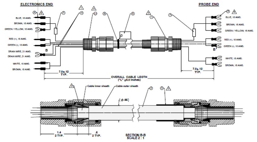
Essential instructions
      Read this page before proceeding!
      Emerson™ designs, manufactures, and tests its products to meet many national and international standards. Because
      these instruments are sophisticated technical products, you must properly install, use, and maintain them to ensure
      they continue to operate within their normal specifications. The following instructions must be adhered to and
      integrated into your safety program when installing, using, and maintaining Emerson products. Failure to follow the
      proper instructions may cause any one of the following situations to occur: loss of life, personal injury, property
      damage, damage to this instrument, and warranty invalidation.
      •   Read all instructions prior to installing, operating, and servicing the product.
      •   If you do not understand any of the instructions, contact your Emerson representative for clarification.
      •   Follow all warnings, cautions, and instructions marked on and supplied with the product.
      •   Inform and educate your personnel in the proper installation, operation, and maintenance of the product.
      •   Install equipment as specified in the installation instructions of the appropriate instruction manual and per
          applicable local and national codes. Connect all products to the proper electrical and pressure sources.
      •   To ensure proper performance, use qualified personnel to install, operate, update, program, and maintain the
          product.
      •   Use only factory documented components for repair. Tampering and unauthorized substitution and parts can
          affect product performance and cause unsafe operation of your process.

      NOTICE
      The Field Communicator must be upgraded to System Software 2.0 with graphic license for operation with the
      Rosemount™ 6888C O2 Transmitter. The AMS software must be upgraded to AMS 8.0 or above. Contact Emerson's
      Global Service Center (GSC) at +1-800-833-8314 to upgrade the Field Communicator software to System Software 2.0
      with graphic license.

      Symbols

                          Earth (ground) terminal

                          Protective conductor terminal

                          Risk of electrical shock

                          Hot surface

                          Refer to Manual.

      The following definitions apply to Warnings, Cautions, and Notices found throughout this publication.

          WARNING
      Highlights an operation or maintenance procedure, practice, condition, statement, etc., which if not strictly observed,
      could result in injury, death, or long-term health hazards of personnel.

          CAUTION
      Highlights an operation or maintenance procedure, practice, condition, statement, etc., which if not strictly observed,
      could result in damage to or destruction of equipment or loss of effectiveness.

2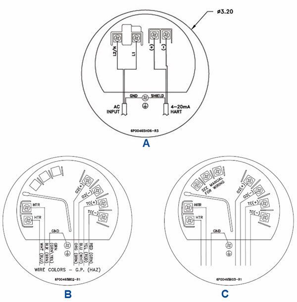
NOTICE
Highlights an essential operating procedure, condition, or statement.

   WARNING
EXPLOSION
Do not open when an explosive atmosphere may be present.

   WARNING
ELECTRIC SHOCK
Do not open while energized.

   WARNING
Physical access
Unauthorized personnel may potentially cause significant damage to and/or misconfiguration of end users’
equipment. This could be intentional or unintentional and needs to be protected against.
Physical security is an important part of any security program and fundamental to protecting your system. Restrict
physical access by unauthorized personnel to protect end users’ assets. This is true for all systems used within the
facility.

   CAUTION
EQUIPMENT DAMAGE
For the standard housing probe and direct replacement probe, only use supply cables & certified cable glands rated >
105 °C (221 °F).

   CAUTION
EQUIPMENT DAMAGE
For the autocal housing, only use supply cables and certified cable glands rated > 85 °C (185 °F).

Special conditions for safe use (ATEX) and conditions of acceptability (CSA)
    1. The unit is to be connected to the supply mains by qualified personnel in accordance with local and national
       codes.

    2. Mounting flange temperature shall not exceed 190 °C during combustion process.

    3. The 6888C O2 Analyzers are used with the 6888 Xi Advanced Electronics (associated equipment not part of this
       certification) which must be installed in a safe area.

    4. Calibration air lines and reference air lines shall not contain pure oxygen or combustible gas other than inert/
       oxygen gas mixture of which oxygen represents no more than that normally present in air.

    5. The pressure within the enclosure and gas lines shall not be higher than 1.1 times the atmospheric pressure
       during the normal operations of the equipment.

    6. Fasteners property class must be A2-70 Stainless Steel

    7. Flameproof joints are not intended to be repaired.

                                                                                                                       3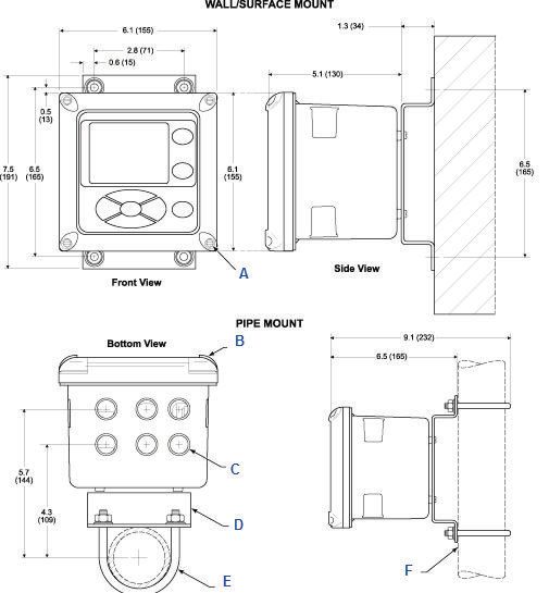
Safety instructions
      SAFETY INSTRUCTIONS FOR THE WIRING AND INSTALLATION OF THIS APPARATUS
      The following safety instructions apply specifically to all EU member states. They should be strictly adhered to in order
      to ensure compliance with the Low Voltage Directive. Non-EU states should also comply with the following unless
      superseded by local or national standards.
          1. Adequate earth connections should be made to all earthing points, internal and external, where provided.

          2. After installation or troubleshooting, all safety covers and safety grounds must be replaced. The integrity of all
             earth terminals must be maintained at all times.

          3. Main supply cords should comply with the requirements of IEC227 or IEC245.

          4. All wiring shall be suitable for use in an ambient temperature of greater than 75 °C (167 °F).

          5. All cable glands used should be of such internal dimensions as to provide adequate cable anchorage.

          6. To ensure safe operation of this equipment, connection to the mains supply should only be made through a
             circuit breaker which will disconnect all circuits carrying conductors during a fault situation. The circuit breaker
             may also include a mechanically operated isolating switch. If not, then another means of disconnecting the
             equipment from the supply must be provided and clearly marked as such. Circuit breakers or switches must
             comply with a recognized standard, such as IEC947. All wiring must conform with any local standards.

          7. All graphical symbols used in this product are from one or more of the following standards: EN61010, IEC417,
             and ISO3864.

          8. Where equipment or labels are marked "Do Not Open While Energized" or similar, there is a danger of ignition
             in areas where an explosive atmosphere is present. This equipment should only be opened when the power
             is removed and adequate time as specified on the label or in the instruction manual has been allowed for the
             equipment to cool down - and then only by trained service personnel.

      The following table illustrates symbols used on equipment or covers and explains the meaning of each.

      Description                                                                       Symbol

      Where equipment or covers are marked with the symbol to the right,
      hazardous voltages are likely to be present beneath. These covers should
      only be removed when power is removed from the equipment - and then
      only by trained service personnel.

      Where equipment or covers are marked with the symbol to the right, there
      is a danger of hot surfaces beneath. These covers should only be removed
      by trained service personnel when power is removed from the equipment.
      Certain surfaces may remain hot to the touch.

      Where equipment or covers are marked with the symbol to the right, refer to
      the Manual for instructions.

4
Manual Contents
00809-0100-4891 January 2023
Contents
Chapter 1 General information.................................................................................................. 7
1.1 Overview....................................................................................................................................... 7
1.2 System configurations................................................................................................................ 7
Chapter 2 Typical system package.......................................................................................... 11
2.1 Rosemount 6888C Hazardous Area Probe product matrix..................................................12
Chapter 3 Specifications............................................................................................................15
3.1 Measurement specifications.................................................................................................... 15
3.2 Environmental specifications...................................................................................................16
3.3 Optional General Purpose 6888 Xi Electronics...................................................................... 16
3.4 Installation specifications - probe........................................................................................... 17
3.5 Installation specifications - Rosemount 6888 Xi with Rosemount 6888C Transmitter
probe............................................................................................................................................ 18
3.6 Installation specifications for traditional architechture Rosemount 6888 Xi for use
with DR or other probe.............................................................................................................. 19
Chapter 4 Install.........................................................................................................................21
4.1 Mechanical installation............................................................................................................. 21
4.2 Mounting the Rosemount 6888 Xi General Purpose Advanced Electronics...................... 21
4.3 Electrical installation................................................................................................................. 25
4.4 Connecting the Hazardous Area Transmitter Probe to the Rosemount General
Purpose 6888 Xi Electronics...................................................................................................... 26
4.5 Connecting the analyzer probe to the single-channel safe area Xi and flame safety
interlock....................................................................................................................................... 28
®
4.6 Connect the analyzer probe with integral autocalibration to HART communications... 33
™
4.7 Connect the analyzer probe with integral autocalibration to FOUNDATION Fieldbus
communications......................................................................................................................... 35
4.8 Connecting the traditional architecture to the direct replacement hazardous area
replacement probe (no electronics inside)..............................................................................41
4.9 Connect traditional architecture system to the direct replacement probe....................... 43
4.10 Pneumatic installation............................................................................................................ 48
Chapter 5 Power up................................................................................................................... 51
5.1 Powering up the standalone Rosemount 6888 Transmitter probe (without
Rosemount 6888 Xi)....................................................................................................................51
5.2 Power up the Rosemount 6888 Analyzer with single/dual channel or single
channel and flame safety interlock Rosemount 6888Xi.........................................................52
5.3 Power up the Rosemount 6888C direct replacement probe (no electronics inside)
with traditional architecture Rosemount 6888Xi....................................................................52
Manual 5Contents Manual
January 2023 00809-0100-4891
5.4 Run Rosemount 6888Xi Quick Start Wizard........................................................................... 53
5.5 Re-initiating Rosemount 6888 Xi wizard.................................................................................54
Chapter 6 Calibration................................................................................................................ 55
6.1 Manual/semi-automatic calibration........................................................................................55
6.2 Fully automatic calibration.......................................................................................................56
Chapter 7 HART® menu trees................................................................................................... 59
Chapter 8 Maintenance and service........................................................................................ 65
8.1 Overview.....................................................................................................................................65
8.2 Maintenance intervals.............................................................................................................. 65
8.3 Repair..........................................................................................................................................66
Chapter 9 Replacement parts...................................................................................................81
Chapter 10 Service support.........................................................................................................83
Appendix A Product certifications..............................................................................................85
6 Rosemount 6888CManual General information
00809-0100-4891 January 2023
1 General information
1.1 Overview
The 6888 is Rosemount's latest combustion flue gas oxygen analyzer. This
product is intended for measuring the flue gases resulting from any combustion
process.
This product uses an in situ sensor, i.e., the sensor is placed at the end of the
probe, and the probe extends directly into the flue gas duct or stack at a given
length. The sensor is like a thermocouple, generating its own millivolt signal
based on the difference between a reference gas (ambient or instrument air -
always 20.95% O2) and the flue gases being measured. This manual covers the
Rosemount 6888C, which is the hazardous area probe version.
This probe can be configured as a blind stand-alone transmitter where HART® or
FOUNDATION Fieldbus™ communications can be used as a method of accessing
the electronics for setup, operation, and diagnostics or with one of several remote
electronics options, as noted below in System configurations. Wiring diagrams for
each of these configurations follow in Electrical installation.
There are several different arrangements of probes, electronics, and features that
are explained below and in the wiring diagrams.
1.2 System configurations
1.2.1 Hazardous Area Transmitter probe only
The Rosemount 6888 probe has the electronics in the blue housing that controls
the heater temperature and also amplifies the raw O2 millivolt signal to a linear
4-20 mA. The 4-20 mA signal lines can be run directly to the control room and also
power the transmitter electronics. As with most other Rosemount transmitters
measuring pressure, temperature, and flow, setup is conducted through HART
communications via a Field Communicator or Asset Management Solutions (AMS).
1.2.2 Standard housing Hazardous Area Transmitter
probe with General Purpose Rosemount 6888 Xi
Electronics
The Rosemount 6888 Xi Electronics serve as a local operator interface unit,
with a back-lit display and keypad. It is capable of two channels, serving two
Rosemount 6888 probes. The Rosemount 6888 Xi also carries these optional
advanced features:
• Fully automatic calibration. Requires Rosemount 6888 Xi O2 Cal Auto
calibration system
Manual 7General information Manual
January 2023 00809-0100-4891
• Loss of flame contact for powering down the heater in the event of a flame-out
condition in a furnace.
• Heaterless operation at process temperatures above 550 °C (1022 °F). This
feature will also permit operation above the heater setpoint of 736 °C (1357
°F). Sensing cell life will be shortened by operation above 800 °C (1472 °F),
however.
• The plugged diffuser diagnostic operates by measuring the return-to-process
rate after calibration gas has been stopped. This feature also includes auto gas
switching when the reading settles out versus waiting for configured gas flow
time to expire.
• Stoichiometer - If a furnace goes into a reducing condition (0% O2), this feature
will determine how far.
• Programmable reference - Permits more accurate readings at near-ambient O2
levels (20.95% O2).
• A cal check capability. New calibration values are not automatically stored after
a calibration. An accept/reject calibration feature can be enabled or disabled so
that the technician or operator can decide to accept or reject a potentially large
change in calibration values.
• Tolerance check that will alarm if the wrong test gases are being used or if a
bottle runs out in the middle of a calibration. Care must be taken to ensure gas
1 and gas 2 calibration gases are properly configured if the tolerance check
feature is enabled.
1.2.3 Hazardous Area Rosemount 6888C probe with
General Purpose Rosemount Xi Electronics with
flame safety interlock
A flame safety interlock by Emerson™ is available for heater power disconnect
whenever there is a loss of the process flame or a heater runaway condition
(heater over-temperature) in the O2 probe. This input is internally powered by the
Rosemount 6888 Xi and is actuated via a dry contact input from the user's flame
scanner. A closed contact indicates a flame is present. An open contact indicates a
loss of flame. This feature is also available with the Integral autocal housing.
1.2.4 Hazardous Area Rosemount 6888C probe with
Integral Autocal General Purpose Rosemount 6888
Xi Electronics
This probe contains gas-switching solenoids so that the Rosemount 6888 Xi
Electronics can control the introduction of calibration gases. Calibrations can be
intiated via a calibration recommended diagnostic, time since last calibration,
manually via external dry contact, HART communications, or from the Rosemount
6888 Xi local operator interface keypad. The integral autocal feature can only be
implemented when the probe is used with a Rosemount 6888 Xi.
8 Rosemount 6888CManual General information
00809-0100-4891 January 2023
1.2.5 Hazardous Area Rosemount 6888C probe with
Integral Autocal and Foundation Fieldbus (FF)
communications
This probe contains gas-switching solenoids that can control the introduction of
calibration gases for calibration. Calibrations can be initiated automatically via
a calibration recommended diagnostic, time since last calibration, or manually
via optional Xi keypad, FF communications via the Field Communicator, or AMS
console. Unlike the HART transmitter electronics, the FF version can execute
automatic calibrations either with or without the optional Rosemount 6888 Xi
Electronics. Likewise, advanced features can be implemented either with or
without the optional Xi.
1.2.6 Hazardous Area Rosemount 6888C direct
replacement (DR) probe with General Purpose
Traditional Architecture Rosemount 6888 Xi
Electronics
Here there are no electronics inside the probe head, so the raw sensor signals for
the heater thermocouple and zirconium oxide O2 sensor are sent to a remote
Rosemount 6888 Xi Electronics. The Rosemount 6888 Traditional Architecture
Electronics will also directly apply power to the probe heater in order to maintain
the correct sensor temperature. This arrangement calls for a 7-conductor cable
to carry this power and the sensor signals. Maximum length for this cable is
200 feet. This probe will also operate on previous Westinghouse/Rosemount
electronics (World Class and Oxymitter), as well as many competitive electronics.
WARNING
HAZARDOUS AREAS
Cables are supplied with Exd Rated Glands; the cable is not ExD rated, and
installation in a hazardous area is the responsibility of the installer/customer.
Cables must be installed in accordance with national and local electrical codes.
1.2.7 Wireless capability
Both the analyzer electronics in the head of the probe and the Rosemount 6888Xi
Electronics communicate over HART communications and can implement wireless
communications via Emerson Wireless 775 THUM™ Adapter.
Manual 9General information Manual January 2023 00809-0100-4891 10 Rosemount 6888C
Manual Typical system package
00809-0100-4891 January 2023
2 Typical system package
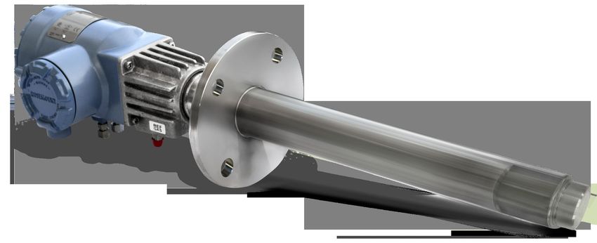
Figure 2-1: Typical System Package
A. Optional Rosemount SPS 4001B or Rosemount IMPS Autocalibration Sequencer
(Requires use of Rosemount 6888 Xi Advanced Electronics option)
B. Quick Start Guide
C. Optional mounting or adapter plate
D. Optional traditional architecture cable
E. HART® Field Communicator package (optional)
F. Optional reference & calibration gas accessories
G. Rosemount 6888C probe
H. Optional Rosemount 6888 XI Advanced Electronics
Manual 11Typical system package Manual
January 2023 00809-0100-4891
2.1 Rosemount 6888C Hazardous Area Probe
product matrix
Table 2-1: Rosemount 6888C Product Matrix
Model Description
Rosemount O2 Transmitter approved for hazardous locations
6888C
Measurement
1OXY Oxygen, standard sensing cell
2OXY Oxygen, high sulfur resistant sensing cell
Probe length(1)
1A 18-in. probe, 3-in. ANSI Class 150 flange
1D 18-in. probe, DIN flange
2A 3-ft probe, 3-in. ANSI Class 150 flange
2D 3-ft probe, DIN flange
3A 6-ft probe, 3-in. ANSI Class 150 flange
3D 6-ft probe, DIN flange
Diffuser
1 Snubber diffuser, 400 °C (572 °F) with process flame arrestors
2 Ceramic diffuser, 825 °C (1517 °F) with process flame arrestors
3 Alloy diffuser 705 °C (1301 °F) with both ambient and process flame arrestors
Housing and electronics
1HT Standard housing, transmitter electronics, HART communications
2HT Integral autocal, transmitter electronics, HART communications
4FF Integral autocal, transmitter electronics, FOUNDATION Fieldbus™ communications
5DR Standard housing, direct replacement, requires remote electronics
6DRY Standard housing, direct replacement, for use with YEW Electronics
Certifications
A ATEX/IECEx
C CSA
Mounting Plate
00 None
04 New installation - square weld plate with ANSI 2 in.(50.8 mm)- 150# studs and flange (2.5 in.
(63.5 mm) process hole required)
05 New installation - square weld plate with DIN studs and flange (2.5 in. (63.5 mm) process
hole required)
08 Adapter to existing ANSI 3 in. (76.2 mm), 150# flange
12 Rosemount 6888CManual Typical system package 00809-0100-4891 January 2023 Table 2-1: Rosemount 6888C Product Matrix (continued) 09 Adapter to existing ANSI 4 in. (101.6 mm), 150# flange 10 Adapter to existing ANSI 6 in. (152.4 mm), 150# flange 11 Adapter to existing ANSI 3 in. (76.2 mm), 300# flange 12 Adapter to existing ANSI 4 in. (101.6 mm), 300# flange 99 Special adapter - provide existing flange dimensions, including thru-hole diameter Manual calibration accessories 00 None 01 Calibration and reference gas flowmeters and reference regulator/filter diffuser 02 Calibration/reference panel Stoichiometer function(2) 0 No 1 Yes Programmable reference function(2) 0 No 1 Yes Extended temperature reference function(2) 0 No 1 Yes Diffuser warning function(2) 0 No 1 Yes (1) Flanges are flat-faced and for mounting only. Flanges are not pressure-rated. (2) FOUNDATION Fieldbus only (for HART versions, order this feature with Rosemount 6888 Xi Electronics) Manual 13
Typical system package           Manual
January 2023             00809-0100-4891

14                        Rosemount 6888C
Manual                                                                                 Specifications
00809-0100-4891                                                                         January 2023

3                 Specifications
3.1               Measurement specifications
3.1.1             Net O2 range
                  Variable 0 - 10% to 0-50% (Xi electronics of 0-50% range)

3.1.2             Accuracy in oxidizing condition
                  ±0.75% of reading at 0.05% O2, whichever is greater. ±1% of full scale for 0-10%
                  ranges and above.

3.1.3             Lowest detectable limit
                  0.02% O2

3.1.4             Process temperature effect
                  Less than 0.05% O2 from 100 to 700 °C (212 to 1292 °F)

3.1.5             System speed of response to calibration gas
                  Initial response in less than 3 seconds; T90 in less than 8 seconds. Response to
                  process gas changes varies depending on process gas velocity and particulate
                  loading of the diffuser.

3.1.6             Calibration validity
                  Presentation of calibration gases matches the bottle value to within 0.02% O2

3.1.7             Accuracy in reducing conditions (requires
                  stoichiometer feature)
                  ±10% of reading or 0.1% O2, whichever is different size

3.1.8             System response in reducing conditions (requires
                  stoichiometer feature)
                  Going from oxidizing to reducing - T90 in 120 seconds
                  Going from reducing to oxidizing - T90 in 30 seconds

Manual                                                                                               15
Specifications Manual
January 2023 00809-0100-4891
3.2 Environmental specifications
3.2.1 Transmitter probe
Process-wetted materials are 316L stainless steel.
3.2.2 Transmitter probe process temperature limits
0 to 705 °C (32 to 1300 °F)
550 to 825 °C (1022 to 1517 °F) with Xi heaterless operation feature(1)
Optional bypass and jacket accessories permit operation to 1050 °C (1922 °F).
3.2.3 Probe electronics ambient temperature limits
-40 to 70 °C (-40 to 158 °F)
3.2.4 Temperature limit as measured inside probe
electronics
-40 to 85 °C (-40 to 185 °F)
3.2.5 DR probe, no electronics inside, ambient
temperature limits
-40 to 90 °C (-40 to 194 °F)
3.3 Optional General Purpose 6888 Xi
Electronics
3.3.1 Material
NEMA® 4X, polycarbonate material
3.3.2 Rosemount 6888 Xi ambient temperature limits
-20 to -50 °C (-4 to 122 °F)
(1) Reduced cell life can be expected if operated continuously at temperatures above 705 °C (1300 °F).
16 Rosemount 6888CManual Specifications
00809-0100-4891 January 2023
3.3.3 Rosemount 6888 Xi temperature limits as
measured inside the electronics housing
-20 to 70 °C (-4 to 158 °F)
3.4 Installation specifications - probe
3.4.1 Probe mounting flange
Vertical or horizontal-3 in. 150 6 in. (152.4 mm) bolt circle
CAUTION
Flanges are flat-faced and for mounting only. Flanges are not pressure-rated. A
2.5 in. (63.55 mm) diameter hole in the process is required.
Spool piece P/N 3D39761G02 is available to offset probe electronics housing from
hot ductwork.
Many adapter flanges are available to mate to existing flanges.
3.4.2 Probe lengths and approximate shipping weights
18 in. (457 mm) package: 16 lb (7.3 kg)
3 ft (0.91 m) package: 21 lb (9.5 kg)
6 ft (1.83 m) package: 27 lb (12.2 kg)
9 ft (2.74 m) package: 33 lb (15.0 kg)
12 ft (3.66 m) package: 39 lb (17.7 kg)
3.4.3 Reference air (optional)
Maximum 2 scfh (1 L/min), clean, dry, instrument-quality air (20.95% O2) regulated
to 5 psi (34 kPa)
3.4.4 Calibration
Semi-automatic or automatic
3.4.5 Cal gases
0.4% O2 and 8% O2 balance N2 recommended. Instrument air may be used as a
high cal gas but is not recommended. 100% nitrogen cannot be used as the low
cal gas. No explosive gases or gases with % O2 greater than that found in ambient
air (i.e., 20.95% O2) can be used.
Manual 17Specifications Manual
January 2023 00809-0100-4891
3.4.6 Calibration gas flow
5 scfh (2.3 L/min) at 15 psi, maximum
3.4.7 Heater electrical power
120/240 V ±10%, 50/60 Hz, 1/2 in. - 14 NPT conduit ports
3.4.8 Traditional architecture cable
200 ft (61 m) maximum length
3.4.9 Power consumption of transmitter probe/integral
autocal probe
776 W maximum during warm-up
3.5 Installation specifications - Rosemount
6888 Xi with Rosemount 6888C Transmitter
probe
3.5.1 Electrical power of optional Rosemount 6888 Xi
Electronics
120/240 V ±10%, 50/60 Hz
3.5.2 Power consumption of Rosemount 6888 Xi
10 W maximum
3.5.3 Rosemount 6888 Xi alarm relays
2 provided- 2 amps, 20 Vdc
3.5.4 Rosemount 6888 Xi optional loss of flame contact
Removes heater power
3.5.5 Electrical noise
3.5.6 Traditional architecture cable
200 ft (61 m) maximum length
18 Rosemount 6888CManual Specifications
00809-0100-4891 January 2023
3.5.7 Transmitter electrical 4-20 mA power
12 - 42 Vdc (looped-powered from the control room or from the Rosemount 6888
Xi box)
3.6 Installation specifications for traditional
architechture Rosemount 6888 Xi for use
with DR or other probe
3.6.1 Power consumption of Rosemount 6888 Xi
120/240 V ±10%, 50/60 Hz, 260/1020 VA max for 120 V probes
120 V ±10%, 50/60 Hz, 450 VA max for 44 V probes
3.6.2 Alarm relay outputs
2 provided - 2 Amperes, 30 Vdc, Form-C
3.6.3 Optional loss of flame input
Internally powered input to remove heater power actuated via dry contact output
form proof of flame device.
Emerson has satisfied all obligations coming from the European legislation to
harmonize the product requirements in Europe.
Manual 19Specifications Manual January 2023 00809-0100-4891 20 Rosemount 6888C
Manual                                                                                              Install
00809-0100-4891                                                                               January 2023

4                 Install
                    WARNING

                  Failure to follow safety instructions could result in serious injury or death.
                  Before installing this equipment, read the Essential instructions at the front of this
                  Reference Manual.

                    WARNING

                  ELECTRIC SHOCK
                  Failure to install covers and ground leads could result in serious injury or death.
                  Install all protective equipment covers and safety ground leads after installation.

4.1               Mechanical installation
                  Most combustion processes run only slightly negative or positive in pressure, so
                  that the probe flange is for mechanical mounting only. The probe is not rated for
                  high pressures. If this is a new installation, Emerson can supply a weld plate for
                  welding to the flue gas duct.

                    WARNING

                  Electric shock
                  Failure to install covers and ground leads could result in serious injury or death.
                  Install all protective covers and safety ground leads after installation.

4.2               Mounting the Rosemount 6888 Xi General
                  Purpose Advanced Electronics
                  Follow the steps below to mount the Rosemount 6888 Xi.

                  Prerequisites
                  The Rosemount 6888 Xi Advanced Electronics is available in a panel mounting or
                  wall/pipe mounting configuration. Refer to Figure 4-1 or Figure 4-2 for the panel,
                  wall, or pipe mounting details. The Rosemount 6888 Xi is rated for use in general
                  purpose locations only.
                  Ensure all components are available to install the Rosemount 6888 Xi.

                  Procedure
                     1. Select a mounting location near or removed from the O2 Probe.

Manual                                                                                                  21
Install Manual
January 2023 00809-0100-4891
Consider the temperature limitations of the Rosemount 6888 Xi (see
Rosemount 6888 Xi ambient temperature limits) when selecting the
mounting location.
2. Mount the Roseount 6888 Xi at a height convenient for viewing and
operating the interface.
Approximately 5 ft (1.5 m) is recommended.
3. The keypad window on the Rosemount 6888 Xi may have interior and
exterior protective membranes. Remove the protective membranes prior
to use of the Rosemount 6888 Xi enclosure.
CAUTION
EQUIPMENT DAMAGE
Failure to remove the protective membranes may cause the display to
appear distorted. The membrane may be difficult or impossible to remove
after extended use at elevated temperatures.
22 Rosemount 6888CManual Install
00809-0100-4891 January 2023
Figure 4-1: Wall/surface mount and pipe mount
A. 4X cover screw
B. Front panel
C. 6X 1/2-in. NPT conduit openings
D. Mounting bracket
E. U-bolts
F. 2-in. pipe supplied by customer
Dimensions are in inches with millimeters in parentheses.
Manual 23Install Manual
January 2023 00809-0100-4891
Figure 4-2: Panel mount
A. Maximum panel thickness 0.375 (9.52)
B. Panel mount gasket
C. 4X mounting brackets and screws provided
D. 6X 1/2 in. NPT conduit openings
NOTICE
Dimensions are in inches with millimeters in parentheses.
24 Rosemount 6888CManual Install
00809-0100-4891 January 2023
NOTICE
The front panel is hinged at the bottom. The panel swings down for easy access to
wiring locations.
4.3 Electrical installation
All wiring must conform to local and national codes. Multiple wiring diagrams are
shown in this section. Always refer to the diagrams that apply to your analyzer
configuration and disregard all other wiring diagrams.
WARNING
ELECTRIC SHOCK
Disconnect and lock out power before connecting the power supply.
Install all protective covers and safety ground leads after installation. Failure to
install covers and ground leads could result in serious injury or death.
To meet the safety requirements of IEC 61010-1 (EC requirement) and ensure safe
operation of this equipment, connect the main electrical power supply through a
circuit breaker (min 10 A) which will disconnect all current-carrying conductors
during a fault situation. This circuit breaker should also include a mechanically
operated isolating switch. If not, keep another external means of disconnecting
the supply from the equipment located close by. Circuit breakers or switches must
comply with a recognized standard such as IEC 947.
WARNING
Before installing this equipment, read the Essential instructions at the front of this
instruction manual. Failure to follow safety instructions could result in serious
injury or death.
CAUTION
EQUIIPMENT DAMAGE
If external loop power is used, the power supply must be a safety extra low
voltage (SELV) type.
NOTICE
To maintain proper earth grounding, ensure a positive connection exists between
the analyzer housing and earth. The connecting ground wire must be 14 AWG
minimum.
NOTICE
Line voltage, signal, and relay wiring should be rated for at least 105 °C (221 °F).
Manual 25Install Manual
January 2023 00809-0100-4891
NOTICE
If metal conduit is used with the Rosemount 6888 Xi, the conduit should be
reliably bonded to protective earth (PE). The grounding plate inside the
Rosemount 6888 Xi is not bonded to PE and does not provide adequate
grounding.
4.4 Connecting the Hazardous Area
Transmitter Probe to the Rosemount
General Purpose 6888 Xi Electronics
The Rosemount 6888 Xi Electronics serve as an operator interface unit with a
back-lit display and keypad. It is capable of two channels, serving two Rosemount
6888 probes.
Procedure
1. Remove cover screws from the front cover of the Rosemount 6888 Xi. Swing
down the front cover of the interface box.
2. Pull out the I/O board on the right side of the card rack inside the
Rosemount 6888Xi.
If your system is configured to operate two transmitter probes, there are
two I/O interface boards.
3. See Figure 4-3. Connect the 4-20 mA signal wires at J4 of the I/O board.
Attach the supplied ferrite clamp over the 4-20 mA OUT wires that extend
past the shield.
NOTICE
Installation of the ferrite clamp over the 4-20 mA OUT wires is required for
compliance with the European EMC directive.
4. Terminate the shield of the 4-20 mA signal wires at the designated ground
terminal of the Rosemount 6888 Xi. Do not allow bare shield wires to
contact the circuit boards. Insulate the shield wires prior to termination.
5. Connect the signal wires from the SPS or IMPS (if used) to the applicable
terminals of J3. Refer to the SPS or IMPS instruction manual for wiring
details.
6. Reinstall the I/O board at the card rack of the Rosemount 6888 Xi.
7. If your system is configured for two channel operation, repeat steps 2
through 6 to connect the other probe's signal wires.
8. Remove the probe's connector from the power supply board located on the
left-hand side of the card rack inside the Rosemount 6888 Xi.
9. Connect the line, or L1, wire to the L1 terminal and the neutral, or L2, wire
to the N terminal.
10. Reinstall the power supply connector in the power supply board.
26 Rosemount 6888CManual Install 00809-0100-4891 January 2023 Figure 4-3: Single/dual channel wiring diagram Manual 27
Install                                                                                            Manual
January 2023                                                                               00809-0100-4891

NOTICE
 1. Except for JP5, JP7, and JP8 on IO board, jumper and switch settings are factory set and are shown for
    reference only.
 2. IO board 4-20 mA/HART® loop power settings
    • JP5
       — Pins 1-2: internal loop power Rosemount 6888 Xi to Rosemount 6888 Transmitter
         — Pins 2-3: external power Rosemount 6888 Xi to Rosemount 6888 Transmitter (requires 2,500
           resistor across J4 PR+ to PR-)
     •   JP7/JP8
         — Pins 1-2: internal power from Rosemount 6888 Xi to DCS
         — Pins 2-3: external power Rosemount 6888 Xi to DCS

4.5                Connecting the analyzer probe to the
                   single-channel safe area Xi and flame
                   safety interlock
                   A flame safety interlock by Emerson is available for the heater power disconnect
                   whenever there is a loss of the process flame or a heater runaway condition
                   (heater over-temperature) in the O2 probe. This input is internally powered by the
                   Rosemount 6888 Xi and is actuated via a dry contact output from the user's flame
                   scanner. A closed contact indicates a flame is present. An open contract indicates
                   a loss of flame.

                   Procedure
                      1. Refer to Figure 4-4. Connect the signal wires from the burner management
                         system flame status output to the flame status input terminals of J2.
                         You must supply the flame status sensing device. Refer to the applicable
                         OEM documents for signal wiring details.
                      2. Remove the J1 and J2 connectors from the AC relay board.
                      3. Connect the AC line input to the J1 connector.
                      4. Connect the AC power to the Rosemount 6888C probe to the J2 connector.
                      5. Reinstall connector J1 and J2 to the AC relay board.
                   Rosemount 6888C product matrix
                   Compare the configuration matrix below to the model number on the probe tag
                   to confirm the features present in this specific probe.
                   Table 4-1: Housing and Electronics
                   1HT             Standard housing, transmitter electronics, HART communications
                   2HT             Integral autocal, transmitter electronics, HART communications

28                                                                                           Rosemount 6888C
Manual Install
00809-0100-4891 January 2023
Table 4-1: Housing and Electronics (continued)
4FF Integral autocal, transmitter electronics, Fieldbus communications
5DR Standard housing, direct replacement, no electronics
6DRY Standard housing, direct replacement, YEW electronics
Rosemount 6888 Xi product matrix - safe area only
Compare the configuration matrix below to the model number on the probe tag
to confirm the features present in this specific probe.
Table 4-2: Remote Type
1OXY Single channel O2
2OXY Single channel O2 with flame safety interlock for heater
3OXY Dual channel O2
4OXY Single channel O2 traditional architecture for 120 V probes
Manual 29Install Manual January 2023 00809-0100-4891 Figure 4-4: Single channel with flame safety wiring diagram 30 Rosemount 6888C
Manual                                                                                                     Install
00809-0100-4891                                                                                      January 2023

NOTICE
 A. See Rosemount 6888 Xi Instruction Manual for additional installation and operating instructions.
 B. All wiring marked with an asterisk (*) is factory wiring inside the Rosemount 6888 Xi.
 C. Except for JP5, JP7, and JP8 on the input/output (IO) board, jumper and switch settings are factory set and are
    shown for reference only.
 D. IO board: 4-20 mA/HART loop power settings
    • JP5
        — Pins 1-2: internal power Rosemount 6888Xi to Rosemount 6888 analyzer
         — Pins 2-5: external power Rosemount 6888Xi to Rosemount 6888 analyzer (requires 2,500 resistor across
           J4, PR+ to PR-)
    •    JP7/JP8
         — Pins 1-2: internal power to DCS
         — Pins 2-3: external power Rosemount 6888Xi to DCS

Manual                                                                                                            31
Install Manual
January 2023 00809-0100-4891
Figure 4-5: Rosemount 6888 Xi front and bottom views
A. Power supply board
B. Channel #2 IO board
C. Shield ground
D. Channel #1 IO board
E. AC input to P/S
F. Plug
G. Channel #2 alarm relay, SPS/IMPS
H. Channel #2 4-20 mA/HART output
I. Channel #1 Alarm relay, SPS/IMPS
J. Channel #1 4-20 mA HART output
32 Rosemount 6888CManual Install
00809-0100-4891 January 2023
4.6 Connect the analyzer probe with integral
autocalibration to HART® communications
This probe contains gas-switching solenoids, Field Communicator, or Asset
Management Solutions (AMS) software, so that the Rosemount 6888Xi Electronics
can control the introduction of calibration gases.
You can initiate calibrations in the following ways
• Automatically with a calibration recommended diagnostic
• Automatically with time since last calibration
• Manually with external dry contact
• Manually with HART communications
• With the Rosemount 6888Xi local operator interface (LOI). You can only use
integral autocalibration with a Rosemount 6888Xi.
Procedure
1. Remove the two covers from the analyzer.
2. Refer to Figure 4-6. Connect the line (L1 wire) to the L1 terminal, the neutral
(L2 wire) to the L2/N terminal, and the ground wire to the ground lug.
The analyzer accepts line voltage at 120/240 Vac ±10 percent, 50/60 Hz. No
setup is required.
3. Connect the 4-20 mA signal wires from the Rosemount 6888Xi to the
connections in the side chamber of the analyzer.
Do not connect the signal wires to the terminals in the main chamber where
the AC input wires are connected. Use a shielded twisted wire pair. Do not
allow bare shield wires to contact the circuit boards. Insulate the shield
wires prior to termination. The 24 VDC loop power is sourced from the
Rosemount 6888Xi.
4. Terminate the shield at both the probe and the Rosemount 6888Xi.
Note
The 4-20 mA signal represents the O2 value and also powers the
probe-mounted electronics. Superimposed on the 4-20 mA signal is
HART information accessible through a Field Communicator or Asset
Management Solutions (AMS) software.
5. Reinstall both covers on analyzer.
6. Follow the remaining electrical installation instructions for the Rosemount
6888Xi included with your system configuration.
Manual 33Install Manual January 2023 00809-0100-4891 Figure 4-6: Integral autocalibration and HART communications A. Ferrite clamp B. Signal C. Test points D. #8 pan htd scr (internal ground) E. Power F. Test point group 34 Rosemount 6888C
Manual                                                                                                     Install
00809-0100-4891                                                                                      January 2023

Note
 A. Except for JP5, JP7, and JP8 on the input/output (IO) board, jumper and switch settings are factory set and are
    shown for reference only.
 B. IO board: 4-20 mA/HART loop power settings
    • JP5
       — Pins 1-2: internal power Rosemount 6888Xi to Rosemount 6888 analyzer
         — Pins 2-5: external power Rosemount 6888Xi to Rosemount 6888 analyzer (requires 2,500 resistor across
           J4, PR+ to PR-)
    •    JP7/JP8
         — Pins 1-2: internal power to DCS
         — Pins 2-3: external power Rosemount 6888Xi to DCS

Note
IO board Channel 2 is a duplicate of Channel 1.

4.7                Connect the analyzer probe with integral
                   autocalibration to FOUNDATION™ Fieldbus
                   communications
                   This probe contains gas-switching solenoids enabling the Rosemount 6888 Xi
                   Electronics, Field Communicator, or Asset Management Solutions (AMS) software
                   to control the introduction of calibration gases.
                   You can initiate calibrations in the following ways
                   •   Automatically with a calibration recommended diagnostic
                   •   Automatically with time since last calibration
                   •   Manually with external dry contact
                   •   With the Rosemount 6888 Xi local operator interface (LOI). You can only use
                       integral autocalibration with a Rosemount 6888 Xi.

                   Procedure
                       1. Remove the two covers from the analyzer.
                       2. Connect the line (L1 wire) to the L1 terminal, the neutral (L2) wire to the
                          L2/N terminal, and the ground wire to the ground lug.
                          The analyzer accepts line voltage at 120/240 VAC ±10 percent, 50/60 Hz. No
                          setup is required.
                       3. Connect the FOUNDATION Fieldbus wires from the analyzer side housing to
                          the FF segment.

Manual                                                                                                            35
Install Manual
January 2023 00809-0100-4891
WARNING
The Rosemount 6888 probe is not rated as intrinsically safe (IS) and will
render any IS or FISCO segment it is wired to as non-IS.
Use a shielded twisted wire pair.
Do not allow bare shield wires to contact the circuit boards.
4. Terminate the shield at both the probe and the Rosemount 6888 Xi
Advanced Electronics.
Note
The FOUNDATION Fieldbus signal represents the O2 value and also powers the
probe-mounted electronics.
5. Reinstall both covers on analyzer.
6. Follow the remaining electrical installation instructions for the Rosemount
6888 Xi included with your system configuration.
Rosemount 6888C ordering information
Compare the ordering information below to the model number on the probe tag
to confirm the features present in this specific probe.
Table 4-3: Housing and electronics ordering information
1HT Standard housing, analyzer electronics, HART communications
2HT Integral autocal, analyzer electronics, HART communications
4FF Integral autocal, analyzer electronics, Fieldbus communications
5DR Standard housing, direct replacement, no electronics
6DRY Standard housing, direct replacement, YEW electronics
36 Rosemount 6888CManual Install
00809-0100-4891 January 2023
Figure 4-7: Integral autocalibration and FOUNDATION Fieldbus communication
without optional Rosemount 6888Xi
A. Signal
B. Not used
C. #8 pan htr scr (internal ground)
D. Power
E. Probe test point group
NOTICE
A. All wiring marked with an asterisk (*) is factory wiring inside the Rosemount
6888 Xi.
B. Except for JP5, JP7, and JP8 on the input/output (IO) board, jumper and switch
settings are factory set and are shown for reference only.
C. IO board: 4-20 mA/HART loop power settings
• JP5
— Pins 1-2: internal power Rosemount 6888Xi to Rosemount 6888 analyzer
— Pins 2-5: external power Rosemount 6888Xi to Rosemount 6888 analyzer
(requires 2,500 resistor across J4, PR+ to PR-)
• JP7/JP8
— Pins 1-2: internal power to DCS
— Pins 2-3: external power Rosemount 6888Xi to DCS
Rosemount 6888Xi ordering information: safe area only
Compare the ordering information below to the model number on the probe tag
to confirm the features present in this specific probe.
Manual 37Install Manual
January 2023 00809-0100-4891
Table 4-4: Remote type ordering information
1OXY Single channel O2
2OXY Single channel O2 with flame safety interlock for heater
3OXY Dual channel O2
4OXY Single channel O2 traditional architecture for 120 V probes
38 Rosemount 6888CManual Install
00809-0100-4891 January 2023
Figure 4-8: Integral autocalibration and FOUNDATION Fieldbus communication
with optional Rosemount 6888Xi
A. Ribbon cable to display board J2 Sensor 1
B. Signal
C. HART® connection (Used as a communication bus from probe analyzer
electronics to optional Rosemount 6888Xi. Not accessible to Field Communicator
or AMS)
D. #8 pan htr scr (internal ground)
E. Power
F. Probe test point group
IO board switch/jumpers
Jumper settings
Manual 39Install Manual
January 2023 00809-0100-4891
JP1 Pins 2-3
JP2 Pins 2-3
JP5 Pins 1-2: internal power
Pins 2-3: external power
JP7 Pins 1-2: internal power
Pins 2-3: external power
JP8 Pins 1-2: internal power
Pins 2-3: external power
SW4 switch settings
• Position 1: Off
• Position 2: Off
• Position 3: Off
• Position 4: Off
NOTICE
A. Except for JP5, JP7, and JP8 on the input/output (IO) board, jumper and switch
settings are factory set and are shown for reference only.
B. IO board 4-20 mA/HART loop power settings
JP5
• Pins 1-2: internal power Rosemount 6888Xi to Rosemount 6888 Analyzer.
• Pins 2-3: external power Rosemount 6888Xi to Rosemount 6888 Analyzer
(requires 2,500 resistor across J4, PR+ to PR-).
JP7/JP8
• Pins 1-2: internal power Rosemount 6888Xi to DCS.
• Pins 2-3: external power Rosemount 6888Xi to DCS.
40 Rosemount 6888CManual Install
00809-0100-4891 January 2023
Figure 4-9: Rosemount 6888 Xi front and bottom view
A. Power supply board
B. AC relay board
C. Shield ground
D. IO board
E. AC input to power supply
F. Plug
G. AC input to relay board
H. AC output to analyzer
I. Alarm relay, Rosemount SPS
4.8 Connecting the traditional architecture to
the direct replacement hazardous area
replacement probe (no electronics inside)
Here there are no electronics inside the probe head, so the raw sensor signals
for the heater thermocouple and zirconium O2 sensor are sent to a remote
Rosemount 6888 Xi Electronics. The Rosemount 6888 Xi electronics will also
directly apply power to the probe heater in order to maintain the correct sensor
Manual 41Install Manual
January 2023 00809-0100-4891
temperature. This arrangement calls for a 7-conductor cable to carry this power
and the sensor signals. Maximum length for this cable is 200 feet.
Procedure
1. Remove cover from probe.
2. Feed all DR probe wiring through the conduit port of probe.
3. Refer to Figure 4-10. Connect DR probe heater power leads to DR probe
connector.
4. Connect O2 signal and thermocouple wires to DR probe connector.
Model 6888C product matrix
Compare the configuration matrix below to the model number on the probe tag
to confirm the features present in this specific probe.
Table 4-5: Housing and Electronics
1HT Standard housing, transmitter electronics, HART communications
2HT Integral autocal, transmitter electronics, HART communications
4FF Integral autocal, transmitter electronics, Fieldbus communications
5DR Standard housing, direct replacement, no electronics
6DRY Standard housing, direct replacement, YEW electronics
Model 6888Xi product matrix - safe area only
Compare the configuration matrix below to the model number on the probe tag
to confirm the features present in this specific probe.
Table 4-6: Remote Type
1OXY Single channel O2
2OXY Single channel O2 with flame safety interlock for heater
3OXY Dual channel O2
4OXY Single channel O2 traditional architecture for 120 V probes
42 Rosemount 6888CManual Install
00809-0100-4891 January 2023
Figure 4-10: Traditional architecture with direct replacement hazardous area replacement
probe (no electronics inside)
NOTICE
A. See Rosemount 6888 Xi Instruction Manual for additional installation and operating instructions.
B. All wiring marked with an asterisk (*) is factory wiring inside the Rosemount 6888 Xi.
C. Except for JP5, JP7, and JP8 on the input/output (IO) board, jumper and switch settings are factory set and are
shown for reference only.
4.9 Connect traditional architecture system to
the direct replacement probe
Use a traditional architecture configuration to provide for remote location of the
analyzer electronics. All electronics are housed inside the Rosemount 6888Xi. A
multi-conductor power/signal cable connects the probe to the Rosemount 6888Xi.
Manual 43Install Manual
January 2023 00809-0100-4891
Use the following procedure to connect the traditional architecture probe to the
Rosemount 6888Xi.
NOTICE
The traditional architecture cable is provided at the specified length and is ready
for installation. The cable glands must be properly terminated to maintain EMC/
electromagnetic interference (EMI) noise protection.
Procedure
1. Run the seven-conductor cable between the traditional architecture probe
and the installation site for the Rosemount 6888Xi.
Use new cable conduit or trough as needed.
2. Install the cable and lead wires to the probe per manufacturer's
instructions.
3. Install the cable at the probe housing and at the Rosemount 6888Xi
enclosure.
a) Unscrew locking nut from gland assembly and slide locking nut back
along cable.
b) Pull the gland body away from the plastic insert.
NOTICE
Use care not to damage the cable shield braid.
c) Insert the cable wires into the proper entry port in either the probe
housing or the Rosemount 6888Xi enclosure.
d) At the probe housing, apply PTFE tape or similar sealing compound
to the tapered pipe threads. Thread the gland body into the probe
housing until properly seated.
e) At the Rosemount 6888Xi enclosure, insert the gland body into the
left front cable port from the inside of the enclosure. Use the rubber
O-ring provided to seal the cable port.
f) Ensure the cable shield braid is evenly formed over the gray insert.
When properly formed, the braid should be evenly spaced around
the circumference of the insert and not extend beyond the narrow
diameter portion.
g) Carefully press the gray insert into the gland body.
The grooves on the insert should align with similar grooves inside the
gland body. Press the insert in until it bottoms out in the gland body.
h) Slide the locking nut up and thread it onto the gland body. Tighten
the locking nut so the rubber grommet inside the plastic insert
compresses against the cable wall to provide an environmental seal.
44 Rosemount 6888CManual Install
00809-0100-4891 January 2023
4. At the Rosemount 6888Xi, connect the cable leads to the connectors on the
analyzer input/output (IO) board.
Figure 4-11: Traditional architecture general purpose cable gland assembly
WARNING
ELECTRIC SHOCK
Disconnect and lock out power before working on any electrical components.
There is voltage up to 240 Vac.
Manual 45Install Manual
January 2023 00809-0100-4891
Figure 4-12: Traditional architecture with direct replacement (DR) probe (no
electronics inside)
Note
A. See the Rosemount 6888 Xi Reference Manual for additional installation and
operating instructions.
B. All wiring marked with an asterisk (*) is factory wiring inside the Rosemount
6888 Xi.
C. Except for JP7 and JP8 on IO board, jumper and switch settings are factory set
and are shown for reference only.
46 Rosemount 6888CManual Install
00809-0100-4891 January 2023
Figure 4-13: Traditional architecture with direct replacement probe (no
electronics inside)
A. Power supply board
B. DR board
C. Shield ground
D. IO board
E. Plug
F. Probe cable
G. AC input
H. Alarm relay, Rosemount SPS
I. 4-20 mA/HART® output
Manual 47Install Manual
January 2023 00809-0100-4891
4.10 Pneumatic installation
4.10.1 Reference air package
After the Rosemount 6888C is installed, connect the reference air set to the
analyzer unit.
Refer to the schematic diagram in Figure 4-14 for a locally assembled reference
air supply.
Instrument air (reference air): 5 psig (0.34 barg) minimum, 8 psig (0.55 barg)
maximum at 2.0 scfh (1.01 L/min) maximum; less than 40 parts per million
total hydrocarbons. Set regulator outlet pressure at 5 psig (0.34 barg). Use the
reference air set or the optional Rosemount SPS 4001B to supply reference air.
Reference air is recommended, or the reference air fittings can be left open to
atmosphere. Rosemount SPS 4001B autocalibration boxes contain reference air
sets.
Figure 4-14: Plant schematic diagram, standard housing
A. Vent
B. Calibration gas: ¼-in. tube
C. To analyzer
D. Reference air flow meter
E. Instrument air supply: 10 psig (0.69 barg) to 80 psig (5.52 barg) pressure
F. ¼-in.-18 NP female inlet connection
G. ¼-in. or 6 mm O.D. tubing (supplied by customer)
H. Reference gas: ¼-in. tube
48 Rosemount 6888CManual Install
00809-0100-4891 January 2023
Figure 4-15: Plant air schematic diagram, accessory housing
A. Vent
B. Calibration gas 1: ¼-in. tube
C. Calibration gas 2: ¼-in. tube
D. To analyzer
E. Reference air flow meter
F. Instrument air supply: 10 psig (0.69 barg) to 80 psig (5.52 barg) pressure
G. ¼-in.-18 NPT female inlet connection
H. ¼-in. or 6 mm O.D. tubing (supplied by customer)
I. Reference gas: ¼-in. tube
Manual 49Install Manual
January 2023 00809-0100-4891
Figure 4-16: Manual calibration panel
Note
Dimensions are in inches with millimeters in parentheses.
50 Rosemount 6888CManual Power up
00809-0100-4891 January 2023
5 Power up
5.1 Powering up the standalone Rosemount
6888 Transmitter probe (without
Rosemount 6888 Xi)
Complete the following steps to power up the Rosemount 6888C Transmitter
probe.
Procedure
1. Apply AC line power to the transmitter.
2. Apply 24 Vdc loop power to the transmitter.
3. Using either the DCS control or a field communicator, verify
communications to the transmitter.
The analyzer probe takes approximately 45 minutes to warm up to the 736 °C
(1357 °F) heater setpoint. The 4-20 mA signal remains at a default value of 3.5 mA,
and the O2 reading remains at 0% through this warm-up period. After warm up,
the probe begins reading oxygen, and the 4-20 mA output is based on the default
range of 0-10% O2.
If there is an error condition at startup, an alarm message is displayed on the
Rosemount 6888Xi.
Manual 51You can also read