Ripper for processing slope fields - E3S Web of Conferences
←
→
Page content transcription
If your browser does not render page correctly, please read the page content below
E3S Web of Conferences 264, 04034 (2021)                                 https://doi.org/10.1051/e3sconf/202126404034
CONMECHYDRO - 2021

      Ripper for processing slope fields
      Berdirasul Khudayarov1, Sherzod Mardonov2, Nurbek Rashidov3, Xasan Sodikov3 and
      Dilshod Baratov4*
      1
        Tashkent Institute of Irrigation and Agricultural Mechanization Engineers, Tashkent, Uzbekistan
      2
        Beshkent Agricultural Technical School under the Tashkent Institute of Irrigation and Agricultural
      Mechanization Engineers, Karshi, Uzbekistan
      3
        Karshi Engineering Economic Institute, Karshi, Uzbekistan
      4
        Karshi branch of Tashkent Institute of Irrigation and Agricultural Mechanization Engineers, Karshi,
      Uzbekistan

                    Abstract. The purpose of the study is to substantiate the parameters of a
                    spherical disk working body. New technology of tillage of slope fields that
                    prevent water erosion, a design scheme of a ripper for its implementation is
                    presented. The ripper consists of lower and upper working bodies of the
                    "paraglider" type and a spherical disk. The study applied the laws and rules
                    of theoretical mechanics, agricultural mechanics, mathematical statistics,
                    and methods of strain measurement and the methods given in the existing
                    regulatory documents (TSt 63.04.2001, TSt 63.03.2001). The new
                    technology of tillage of slope fields makes it possible to form step ridges
                    on the surface of the arable land and on the bottom of the furrow, which
                    protects the soil of the slopes from water erosion. It is established that
                    when the diameter of the spherical disk of 510 mm, the curvature radius of
                    56 mm, tilt angle relative to the direction of motion of 28-30° to the
                    vertical at an angle of 17-18°, the transverse and longitudinal distance
                    between the disc and work on the bottom ripper respectively 30 and 20 cm
                    ensures the formation of ridges on the surface of the field according to
                    agrotechnical requirements at a minimum cost of energy.

      1 Introduction
      Currently, the leading position is occupied by developing and implementing energy - and
      resource-saving, and highly efficient machines for tillage. If we consider that " 31% of the
      land is subject to water erosion, and 34% to wind erosion, and annually more than 60
      billion tons "tons of fertile soil is washed into the world ocean" [5-6, 9, 17, 24-25, 27-30],
      then the development of energy - and resource-saving machines and tools that protect the
      soil from wind and water erosion is considered an important task.
           In the world, research works are being conducted aimed at developing soil protection
      technologies for protecting the soil from wind and water erosion and technical means for
      their implementation [32-33]. It is relevant to conduct targeted scientific research on the
      development of dump and non-dump anti-erosion working bodies, ensuring resource

      *
          Corresponding author: sh.doniyorbek@mail.ru

© The Authors, published by EDP Sciences. This is an open access article distributed under the terms of the Creative Commons
Attribution License 4.0 (http://creativecommons.org/licenses/by/4.0/).
E3S Web of Conferences 264, 04034 (2021) https://doi.org/10.1051/e3sconf/202126404034
CONMECHYDRO - 2021
conservation in the processes of their interaction with the soil.
Research on the development and application of machinery to protect the soil from water
and wind erosion, in particular machinery working bodies of the "paraplu", studying their
performance and justification of the parameters studied F.Mamatov [1-23], B.Mirzayev [4-
12, 14-23] V.Alexandrian [28], A.Vagin [29], N.N.Nagorny [30], V.Svetlichniy [30],
V.M.Drinca [32], D.A.Tryapitsyn [34], Pazova T [33], B.Borisenko [32] and others.
The machines and tools created as a result of these studies are used with certain positive
results in the tillage of the slopes. However, these studies have not sufficiently studied the
issues of substantiating the parameters of the disk working bodies of rippers that form
ridges on the surface of the field to protect the soil from water erosion and ensure high
quality of work with minimal energy costs [38-39].
The purpose of the study is to substantiate the parameters of a spherical disk working body.
2 Methods
The study applied the laws and rules of theoretical mechanics, agricultural mechanics,
mathematical statistics, and methods of strain measurement and the methods given in the
existing regulatory documents (TSt 63.04.2001, TSt 63.03.2001).
Analysis of studies has shown that the prevention of water erosion and increasing the
degree of soil crumbling, as well as reducing fuel consumption, labor, and other costs when
processing slope fields, can be achieved by using a ripper that forms ridges on the surface
of the arable land and at the bottom of the furrow.
Fig. 1. Scheme of soil loosening technology and formation of ridges on slope fields: A, B, A1, B1 are
grooves and ridges, respectively
The loosening of the soil and the formation of ridges are carried out on inclined fields
simultaneously (Fig.1). The technology is carried out as follows: at first, the soil of the
slope field is loosened in the form of steps without a fall. In this case, the bottom of the
furrow of the loosened layer looks like in Fig.1. On the surface of the loosened layer, ridges
B, B are formed due to the formation of grooves A, Ot. In this case, rain precipitation is
absorbed into the loosened layer. Due to the different heights of the steps, the soil water
does not flow down the slope.
2E3S Web of Conferences 264, 04034 (2021) https://doi.org/10.1051/e3sconf/202126404034
CONMECHYDRO - 2021
Fig. 2. Technological process of the ripper equipped with spherical disks: 1 is frame; 2, 3 are lower
and upper rippers with an inclined rack; 4 are inclined ripper racks; 5 is knife; 6 are chisels; 7 is field
board; 8 is plate; 9 is spherical disk; 10 is turning lever
A ripper scheme has been developed to implement the above technology, equipped with
lower and upper ripping working bodies of the "paraglau" type and a spherical disk (Fig. 2).
The slope of slope fields in the Republic, especially in the Kashkadarya region, is 3-12°. At
the same time, the protection of the slope soil from water erosion depends on the
parameters of the ridge
The ridge parameters, in addition to the slope of the field, depending on the amount of
precipitation, their duration, and variety. In this regard, in the autumn months of 2017-
2018, ridges of various cross-sectional areas and sizes were formed on the slope fields with
the help of hand tools. These ridges were preserved in their natural form until the sowing
works. Based on these studies, it was found that the cross-sectional area of the ridge is at
least 97.5 cm2.
The technological process of forming ridges in the direction of the slope of the slopes of
agricultural fields according to agrotechnical requirements can be carried out by cutting out
a layer of a certain cross-section and turning it in the direction of the slope.
For the formation of ridges and furrows on the surface of the arable land, a working
body of the spherical disk type is selected. It is equipped with a turning mechanism. The
spherical disk rotation mechanism parameters include the length of the handle OA=R, the
length of the slot in the lever ln, and the length of the hydraulic cylinder rod AA2 (Fig 3).
3E3S Web of Conferences 264, 04034 (2021) https://doi.org/10.1051/e3sconf/202126404034
CONMECHYDRO - 2021
Fig. 3. Scheme for determining the parameters of the rotary mechanism
Considering that the disk rack is installed on the side of its working surface and the design
features of attaching the rack to the frame, the length of the lever R is assumed to be 130
mm.
To move the spherical disk from the working position of the CL to the next one-A2, the
lever must turn to position A1. From Fig. 3, the length of the AB slot in the lever is
determined by the following expression
АВ=R-Rcost=R(1-cost). (1)
Given that to move the lever to the final position of OA2, it must rotate at an angle of t=50º-
60º and R=130 mm, we find AB=65 mm. The length of the rod is determined from the
triangle OAB 1: ls=2AB 1=224 mm. To implement the working process of this mechanism,
a hydraulic cylinder C-40 was selected; its piston stroke is 250 mm.
The width of the formed ridge depends on the distance of the spherical disk throwing
the soil particles in the transverse direction. The distance of the discarding of soil particles
by a spherical disk is found by the following formula
а cos a sin( ) а 2 sin( ) 2 ghn (2)
Ху
g
where, va is the absolute velocity of the soil particles thrown by the spherical disk, m/s; a is
the angle of the spherical disk to the direction of movement of the unit, degree; hn is the
difference of the horizontal planes formed by furrows and ridges based on the slope of the
field, m. ξ is the central angle of the arc of the spherical disk, degree; g is the acceleration
of gravity, m/s2.
The range of transverse rejection of soil particles by a spherical disk can be determined
by the following expression (Figure 4).
4E3S Web of Conferences 264, 04034 (2021) https://doi.org/10.1051/e3sconf/202126404034
CONMECHYDRO - 2021
Fig. 4. Scheme for determining the range of transverse discarding of soil by a spherical disk
а cos a sin( ) а 2 sin( ) 2 ghn b , (3)
Х k d
sin
g 2
From (3), we see that the range of cross drop of soil particles Hc depends on the
absolute velocity of a spherical disc, the angle of incidence of the soil, slope fields, and the
width of the disk.
Figure 5 shows graphs of the dependence of the cross-drop distance of the soil on the
absolute velocity Va and the angle of installation of the disk.
а) α=28º; hп=0,01 m b) Vа=2,0 m/s; hп=0,01 m
Fig. 5. Graphs of changes in Hc as a function of Va, α, and hp
The graphs analysis shows that to place the discarded soil particles along the axis of the
formed ridge, the speed of movement of the spherical disk should be 1,75-25,05 m/s, and
the installation angle should be within 28-30°.
The minimum transverse distance from the post of the lower ripper to the spherical disk
was determined taking into account the zone of soil deformation of the bit of the upper
ripper:
5E3S Web of Conferences 264, 04034 (2021) https://doi.org/10.1051/e3sconf/202126404034
CONMECHYDRO - 2021
Lkp bki bi аi сtg 1bk R 2 ( R a d ) 2 sin . (4)
The calculations performed by expression (4) at bk=35 cm, bk=10 cm, bi=6 cm, ψ1=45°,
R=25,5 cm, ai=25 cm, and ad=12 cm showed that at a transverse distance between the lower
ripper stand and the spherical disk of at least 18 cm, their clogging with soil is excluded.
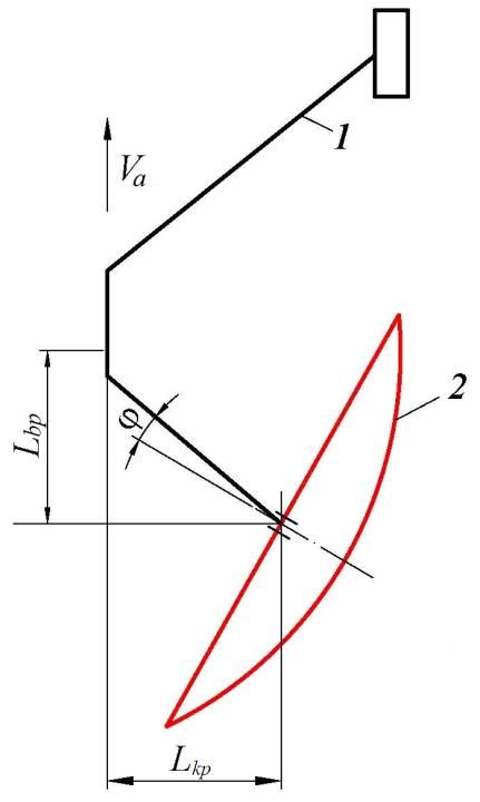
According to Fig.7, the longitudinal distance from the spherical disk to the lower ripper
rack is determined by the following expression:
2 [bkp bi аi сtg 1 bk R 2 ( R a d ) 2 sin ] t t
Lbp , (5)
2 cos( )
where tt is the thickness of the ripper stand, cm;
According to the formula (5), for Lbp=20-26 cm, tt=5 cm, α=30° if=30°, the longitudinal
distance between the lower ripper stand and the spherical disk should be at least 26 cm.
The minimum longitudinal distance from the upper ripper to the spherical disk is
determined from the condition that the soil deformation zone treated with the upper ripper
bit does not reach the structural elements of the spherical disk:
Lbi bt H kt sin b li cos i аi сtg R 2 ( R a d ) 2 cos (6)
where bt is width stone burner ripper, cm; Nkt is the slant height of the rack, cm; li are length
drill bits, cm; ψ is the angle of shearing the soil in the longitudinal direction, degree.
Calculations carried out according to expression (6) at bt=200 mm, ai=65°, φ=30°,
Nkm=0,20 m, βb=25° showed that the longitudinal distance between the upper ripper rack
and the spherical disk should be at least 33 cm.
3 Results and Discussion
In experimental research studied the effect of the scheme relative position of the working
bodies on the frame, the transverse and longitudinal distances between the spherical disk
and lowered the working body, parameters spherical disk, and the operating speed of the
traction resistance of the cultivator, the degree of cracking of the soil and the height of the
ridge, and in the second stage was conducted multivariate experiments with the use of
mathematical planning of experiments.
According to the data of the conducted one-factor experiments, it was found that at
speeds of 6-9 km/h to ensure the required quality of work and the height of the ridge with
minimal energy consumption, the spherical disk should be installed at an angle of 28-30° to
the direction of movement, the transverse and longitudinal distance between the disk and
the lower ripper should be 30 and 20 cm, respectively.
6E3S Web of Conferences 264, 04034 (2021) https://doi.org/10.1051/e3sconf/202126404034
CONMECHYDRO - 2021
Fig. 6. Scheme for determining the longitudinal distance between the spherical disk and the lower
ripper rack: 1 is the lower ripper; 2 is the spherical disk
According to the results obtained at speeds of 6-9 km/h to ensure the required quality of
work with minimal energy consumption, the angle of installation of the spherical disk to the
direction of movement should be within 28-30° and the transverse distance between the
lower ripper and the spherical disk 18-20 cm. These results correspond to the results of
theoretical studies.
4 Conclusions
1. The new technology of tillage of slope fields makes it possible to form step ridges on
the surface of the arable land and the furrow's bottom.
2. The ripper's most optimal design scheme is considered a scheme consisting of upper
and lower working bodies with inclined posts of the "paraglider" type and a ridge
shaper of the spherical disk type.
3. With a diameter of a spherical disk of 510 mm, a radius of curvature of 56 mm, an
angle of installation relative to the direction of movement of 28-30°, and to the
vertical at an angle of 17-18°, the formation of ridges on the surface of the field is
ensured following agricultural requirements with minimal energy consumption.
4. At the transverse and longitudinal distance between the disc working body and the
lower ripper, respectively, 30 and 20 cm, the width and length of the field board,
respectively, 7 and 18 cm, clogging of the working bodies with plant residues is
excluded, high-quality loosening of the soil and stable movement of the ripper are
ensured.
7E3S Web of Conferences 264, 04034 (2021) https://doi.org/10.1051/e3sconf/202126404034
CONMECHYDRO - 2021
References
1. Mamatov, F.M., Eshdavlatov, E., Suyunov, A. The Shape of the Mixing Chamber of
the Continuous Mixer // Jour of Adv Research in Dynamical & Control Systems, Vol.
12, 07-Special Issue, (2020). DOI: 10.5373/JARDCS/V12SP7/20202318 ISSN 1943-
023X.
2. Mamatov, F., Ergashev, I., Ochilov, S., Pardaev, X. Traction Resistance of Soil
Submersibility Type "Paraplau" // Jour of Adv Research in Dynamical & Control
Systems, Vol.12, 07-Special Issue, (2020). DOI:
10.5373/JARDCS/V12SP7/20202336 ISSN1943-023X.
3. Aldoshin, N., Mamatov, F., Ismailov, I., Ergashov, G. Development of combined
tillage tool for melon cultivation // 19th international scientific conference engineering
for rural development Proceedings, Jelgava, 20. (2020). Volume 19. ISSN 1691-5976.
DOI:10.22616/ERDev.2020.19.TF175.
4. Umurzakov, U., Mirzaev, B., Мaмatov, F., Ravshanov, H., Kurbonov, S. A rationale
of broach-plow's parameters of the ridge-stepped ploughing of slopes // XII
International Scientific Conference on Agricultural Machinery Industry IOP Conf.
Series: Earth and Environmental Science 403(2019) 012163 IOP Publishing
doi:10.1088/1755-1315/403/1/012163.
5. Mirzaev, B., Mamatov, F., Chuyanov, D., Ravshanov, X., Shodmonov, G.,
Tavashov, R and Fayzullayev, X. Combined machine for preparing soil for
cropping of melons and gourds // XII International Scientific Conference on
Agricultural Machinery Industry. doi.org/10.1088/1755-1315/403/1/012158.
6. Mirzaev, B., Mamatov, F., Ergashev, I., Ravshanov, H., Mirzaxodjaev, Sh., Kurbanov,
Sh., Kodirov, U and Ergashev, G. Effect of fragmentation and pacing at spot
ploughing on dry soils // E3S Web of Conferences 97.
doi.org/10.1051/e3sconf/201913501065.
7. Mamatov, F., Mirzaev, B., Shoumarova, M., Berdimuratov, P., Khodzhaev, D. Comb
former parameters for a cotton seeder// International Journal of Engineering and
Advanced Technology (IJEAT) Volume-9 Issue1 October/ DOI:
10.35940/ijeat.A2932.109119.
8. Mamatov, F., Mirzaev, B., Batirov, Z., Toshtemirov, S., Tursunov, O., Bobojonov, L.
Justification of machine parameters for ridge forming with simultaneous application
of fertilizers // CONMECHYDRO – 2020 IOP Conf. Series: Materials Science and
Engineering 883(2020) 012165 IOP Publishing. doi:10.1088/1757-
899X/883/1/012165.
9. Mirzaev, B., Mamatov, F., Avazov, I., Mardonov, S. Technologies and technical
means for anti-erosion differentiated soil treatment system // E3S Web of
Conferences. doi.org/10.1051/e3sconf/20199705036.
10. Aldoshin, N., Didmanidze, O., Mirzayev, B., Mamatov, F. Harvesting of mixed crops
by axial rotary combines // Proceeding of 7th International Conference on Trends in
Agricultural Engineering 2019. 17th-20th Prague, Czech Republic. – pp.20-26.
September (2019).
11. Mirzaev, B., Mamatov, F., Aldoshin, N and Amonov, M. Anti-erosion two-stage
tillage by ripper// Proceeding of 7th International Conference on Trends in
Agricultural Engineering 17th-20th. Prague, Czech Republic. – pp.391-396.
September (2019)
12. Mirzaev, B., Мaмatov, F., Ergashev, I., Islomov, Yo., Toshtemirov, B., Tursunov O.
Restoring degraded rangelands in Uzbekistan // Procedia Environmental Science
№ 6. – pp 395-404. (2019).
13. Uzakov, Z.U., Mamatov, F.M., Begulov, O. Implementation of object-oriented
8E3S Web of Conferences 264, 04034 (2021) https://doi.org/10.1051/e3sconf/202126404034
CONMECHYDRO - 2021
Programming technology in the one-dimensional oil displacement problem //
International Conference on information Science and Communications Technologies:
ICISCT 2019/0012008. Tashkent, Uzbekistan. INSPEC Accession
Number: 19412491. DOI: 10.1109/ICISCT47635.2019.9012008.
14. Mamatov, F., Mirzaev, B., Berdimuratov, P., Turkmenov, Kh., Muratov, L.,
Eshchanova, G. The stability stroke of cotton seeder moulder // CONMECHYDRO –
(2020). IOP Conf. Series: Materials Science and Engineering 883 (2020) 012145 IOP
Publishing. doi:10.1088/1757-899X/883/1/012145.
15. Mamatov, F., Mirzaev, B., Tursunov, O. A Justification of Broach-Plow's Parameters
of the Ridge-Stepped Ploughing // E3S Web of Conferences 97, 05035 (2019).
doi.org/10.1051/e3sconf/20199705035.
16. Ahmedov, B.J., Mirzaev, B.S.,Mamatov, F.M., Khodzhaev, D.A., Julliev, M.K.
Integrating of gis and gps for ionospheric perturbations in d- And f-layers using vlf
receiver // InterCarto, InterGIS 26, - pp. 547-560. DOI: 10.35595/2414-9179-2020-1-
26-547-560.
17. Mamatov, F., Mirzaev, B., Tursunov, O., Ochilov, S and Chorieva, D. Relief, physico-
mechanical and technological properties of soil in the cotton growing area // ICECAE
(2020). IOP Conf. Series: Earth and Environmental Science 614(2020) 012169. IOP
Publishing. doi:10.1088/1755-1315/614/1/012169.
18. Shamsutdinov, Z., Ubaydullaev, Sh., Shamsutdinov, N., Mirzaev, B., Mamatov, F.,
and Chorshabiyev, N. The concept of the phytogenic field: theory, research experience
and practical significance // ICECAE 2020. IOP Conf. Series: Earth and
Environmental Science 614(2020) 012164. IOP Publishing. doi:10.1088/1755-
1315/614/1/012164.
19. Umurzakov, U., Mamatov, F., Aldoshin, N., and Mirzaev, B. Exploration of tillage
technologies in the Republic of Uzbekistan // ICECAE (2020) IOP Conf. Series: Earth
and Environmental Science 614(2020) 012168. IOP Publishing. doi:10.1088/1755-
1315/614/1/012168.
20. Mamatov, F., Aldoshin, N., Mirzaev, B., Ravshanov, H., Kurbаnov, Sh and
Rashidov, N. Development of a frontal plow for smooth, furless plowing with
cutoffs // IPICSE 2020. IOP Conf. Series: Materials Science and Engineering 1030
(2021) 012135 IOP Publishing. doi:10.1088/1757-899X/1030/1/012135.
21. Мamatov, F., Mirzaev, B., Mirzahodzhaev, Sh., Uzakov, Z and Choriyeva, D.
Development of a front plow with active and passive working bodies // IPICSE
(2020). IOP Conf. Series: Materials Science and Engineering 1030 (2021) 012164.
IOP Publishing. doi:10.1088/1757-899X/1030/1/012164.
22. Mamato, F.M., Eshdavlatov, E., Suyuno, А. Continuous Feed Mixer Performance
//Journal of Advanced Research in Dynamical and Control Systems (JARDCS). –
Volume-12, 07-Spesia1 Issue, (2020). DOI: 10.5373/JARDCS/V12SP7/20202343.
ISSN 1943-023X.
23. Mamatov, F., Ergashev, I., Mirzaev, B., Pardaev, X, Chorieva, D. Research of the
Penetration Process of the Frontal Plow // 2nd Bukittinggi International Conference on
Education (BICED) (2020). Journal of Physics: Conference Series 1779 (2021)
012002. IOP Publishing. doi:10.1088/1742-6596/1779/1/012002.
24. Kodirov, U., Aldoshin, N., Ubaydullayev, Sh., Sharipov, E., Muqimov, Z and
Tulaganov, B. The soil preparation machine for seeding potatoes on comb //
CONMECHYDRO – (2020) IOP Conf. Series: Materials Science and Engineering
883(2020) 012143 IOP Publishing doi:10.1088/1757-899X/883/1/012143.
25. Ravshanov, Kh., Fayzullaev, Kh., Ismoilov, I., Irgashev, D., Mamatov, S. The
machine for the preparation of the soil in sowing of plow crops under film //
CONMECHYDRO – (2020) IOP Conf. Series: Materials Science and Engineering
9E3S Web of Conferences 264, 04034 (2021) https://doi.org/10.1051/e3sconf/202126404034
CONMECHYDRO - 2021
883(2020) 012138 IOP Publishing doi:10.1088/1757-899X/883/1/012138.
26. Ravshanov, H, Babajanov, L, Kuziev, Sh, Rashidov, N, Kurbanov, Sh. Plough hitch
parameters for smooth tails// CONMECHYDRO – 2020 IOP Conf. Series: Materials
Science and Engineering 883(2020) 012139 IOP Publishing doi:10.1088/1757-
899X/883/1/012139.
27. Chuyanov, D., Shodmonov, G.,Avazov, I., Rashidov, N, Ochilov, S. Soil preparation
machine parameters for the cultivation of cucurbitaceous crops // CONMECHYDRO
– (2020) IOP Conf. Series: Materials Science and Engineering 883(2020) 012139 IOP
Publishing doi:10.1088/1757-899X/883/1/012122.
28. Mamatov F.M., Mirzaev B.S., Avazov I.Zh.. Agrotehnicheskie osnovy sozdanija
protivojerozionnyh vlagosberegajushhih tehnicheskih sredstv obrabotki pochvy v
uslovijah Uzbekistana // – Prirodoobustrojstvo, [In Russian]. (2014).
29. Mamatov F.M., Mirzaev B.S. Erosion preventive technology of crested ladder-shaped
tillage and plow design // European Applied Sciences. Stuttgart (Germany), – pp. 71-
73. (2014).
30. Lobachevskij Ja.P., Mamatov F., Jergashev I.T. Frontal'nyj plug dlja hlopkovodstva //
– Hlopok, № 6. – 35-37 str. [In Russian]. (1991).
31. Alexandryan K, Gasparyan A, Karakhanyan K Machines for the development of
mountain slopes and combat water erosion of soil (Agropromizdat). (1985).
32. Vagin A Mechanization of soil protection from water erosionin the Nonchernozem
strip (Kolos). (1977)
33. Nagorniy N Technologies and means of mechanization for soil protection from
erosion on arable slope lands of Ukrainep 34. (1989).
34. Svetlichniy A, Cherniy S, Shvebs G 2004 Erososcience theoretical and applied
aspects(ITD University Book)
35. Drincha V, Borisenko I, Pleskachev Y Agrotechnical aspects of the development of
soilprotective technologies(Transit). (2004).
36. Pazova T Technologies and means of mechanization for anti-erosion treatment of
sloping soils of the Kabardino-Balkarian Republicp 32. (2009).
37. Tryapitsyn D.A. Justification of the parameters of the chisel working body with
an upright tilted in the transverse vertical plane // Research and development of
tillage and sowing machines. Tr. VISCOM. - M., -pp. 61-70. (1988).
38. Fayzullayev, Kh, Mamatov, S, Radjabov, M, Sharipov, Sh, Tavashov, R and
Nurmanova, M. The quality of loosening the soil with subsoilers of the
combined machine // IPICSE (2020). IOP Conf. Series: Materials Science and
Engineering 1030 (2021) 012171.IOP Publishing. doi:10.1088/1757-
899X/1030/1/012171.
39. Temirov, I, Ravshanov, Kh, Fayzullaev, Kh, Ubaydullaev, Sh and Kodirov, U.
Development of a machine for preparing the soil for sowing melons under the
film // IPICSE (2020). IOP Conf. Series: Materials Science and Engineering 1030
(2021) 012169. IOP Publishing. doi:10.1088/1757-899X/1030/1/012169.
10You can also read


