Power Xpert Release trip units for Power Defense molded case circuit breakers - MN012007EN - Eaton
←
→
Page content transcription
If your browser does not render page correctly, please read the page content below
MN012007EN

Power Xpert ® Release trip units for Power Defense
molded case circuit breakers
DISCLAIMER OF WARRANTIES AND LIMITATION OF LIABILITY
The information, recommendations, descriptions and safety notations in this document are based on Eaton Corporation’s
(“Eaton”) experience and judgment and may not cover all contingencies. If further information is required, an Eaton sales
office should be consulted. Sale of the product shown in this literature is subject to the terms and conditions outlined in
appropriate Eaton selling policies or other contractual agreement between Eaton and the purchaser.
THERE ARE NO UNDERSTANDINGS, AGREEMENTS, WARRANTIES, EXPRESSED OR IMPLIED, INCLUDING WARRANTIES
OF FITNESS FOR A PARTICULAR PURPOSE OR MERCHANTABILITY, OTHER THAN THOSE SPECIFICALLY SET OUT IN ANY
EXISTING CONTRACT BETWEEN THE PARTIES. ANY SUCH CONTRACT STATES THE ENTIRE OBLIGATION OF EATON. THE
CONTENTS OF THIS DOCUMENT SHALL NOT BECOME PART OF OR MODIFY ANY CONTRACT BETWEEN THE PARTIES.
In no event will Eaton be responsible to the purchaser or user in contract, in tort (including negligence), strict liability or other-
wise for any special, indirect, incidental or consequential damage or loss whatsoever, including but not limited to damage or
loss of use of equipment, plant or power system, cost of capital, loss of power, additional expenses in the use of existing
power facilities, or claims against the purchaser or user by its customers resulting from the use of the information, recom-
mendations and descriptions contained herein. The information contained in this manual is subject to change without notice.

ii               PXR trip units for Power Defense molded case circuit breakers MN012007EN January 2022 www.eaton.com
MN012007EN
Contents
1. INTRODUCTION TO THE POWER XPERT® RELEASE TRIP UNIT . . . . . . . . . . . . 1
1.1 Protection settings overview . . . . . . . . . . . . . . . . . . . . . . . . . . . . . . . . . . . . . . . . . 1
1.2 Metering features. . . . . . . . . . . . . . . . . . . . . . . . . . . . . . . . . . . . . . . . . . . . . . . . . . 4
1.3 Health monitor . . . . . . . . . . . . . . . . . . . . . . . . . . . . . . . . . . . . . . . . . . . . . . . . . . . . 5
1.4 Communication features. . . . . . . . . . . . . . . . . . . . . . . . . . . . . . . . . . . . . . . . . . . . . 6
1.5 Control features. . . . . . . . . . . . . . . . . . . . . . . . . . . . . . . . . . . . . . . . . . . . . . . . . . . . 6
2 PXR USER INTERFACE. . . . . . . . . . . . . . . . . . . . . . . . . . . . . . . . . . . . . . . . . . . . . 7
2.1 Key interface elements . . . . . . . . . . . . . . . . . . . . . . . . . . . . . . . . . . . . . . . . . . . . . 7
2.2 PXR 25, PXR 25 Motor Protection, and 20D display with keypad. . . . . . . . . . . . . 9
2.3 PXR 20 with rotary switches. . . . . . . . . . . . . . . . . . . . . . . . . . . . . . . . . . . . . . . . 10
2.4 PXR 10 simplified rotary switches . . . . . . . . . . . . . . . . . . . . . . . . . . . . . . . . . . . 10
2.5 PXR 10 motor protection simplified rotary switches. . . . . . . . . . . . . . . . . . . . . . 11
3 PROTECTION SETTING DESCRIPTION. . . . . . . . . . . . . . . . . . . . . . . . . . . . . . . 11
3.1 Long delay pickup and time setting. . . . . . . . . . . . . . . . . . . . . . . . . . . . . . . . . . . 11
3.2 Short delay pickup and time settings. . . . . . . . . . . . . . . . . . . . . . . . . . . . . . . . . . 12
3.3 Instantaneous pickup setting. . . . . . . . . . . . . . . . . . . . . . . . . . . . . . . . . . . . . . . . 12
3.4 Ground fault settings. . . . . . . . . . . . . . . . . . . . . . . . . . . . . . . . . . . . . . . . . . . . . . 12
3.5 Motor Protection settings description. . . . . . . . . . . . . . . . . . . . . . . . . . . . . . . . . 14
3.6 Maintenance Mode protection. . . . . . . . . . . . . . . . . . . . . . . . . . . . . . . . . . . . . . . 16
3.7 Override. . . . . . . . . . . . . . . . . . . . . . . . . . . . . . . . . . . . . . . . . . . . . . . . . . . . . . . . 17
3.8 Zone selective interlocking (ZSI). . . . . . . . . . . . . . . . . . . . . . . . . . . . . . . . . . . . . .17
3.9 Operating temperature. . . . . . . . . . . . . . . . . . . . . . . . . . . . . . . . . . . . . . . . . . . . . 18
4 COMMUNICATION FUNCTIONALITY . . . . . . . . . . . . . . . . . . . . . . . . . . . . . . . . 18
4.1 Integrated Modbus - remote terminal unit (RTU). . . . . . . . . . . . . . . . . . . . . . . . . 18
4.2 USB port. . . . . . . . . . . . . . . . . . . . . . . . . . . . . . . . . . . . . . . . . . . . . . . . . . . . . . . . 19
4.3 External communications adapter modules (CAMs). . . . . . . . . . . . . . . . . . . . . . 19
5 EXTERNAL WIRING OF THE TRIP UNIT. . . . . . . . . . . . . . . . . . . . . . . . . . . . . . . 20
5.1 Wiring table . . . . . . . . . . . . . . . . . . . . . . . . . . . . . . . . . . . . . . . . . . . . . . . . . . . . . 20
5.2 Auxiliary power. . . . . . . . . . . . . . . . . . . . . . . . . . . . . . . . . . . . . . . . . . . . . . . . . . . 21
5.3 General purpose relay mapping. . . . . . . . . . . . . . . . . . . . . . . . . . . . . . . . . . . . . . 21
5.4 Neutral voltage sensor . . . . . . . . . . . . . . . . . . . . . . . . . . . . . . . . . . . . . . . . . . . . . 24
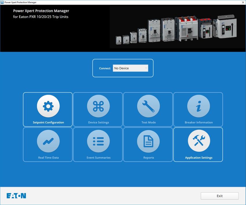
6 POWER XPERT® PROTECTION MANAGER - CONFIGURATION SOFTWARE.25
6.1 Set point configuration through PXPM . . . . . . . . . . . . . . . . . . . . . . . . . . . . . . . . 25
6.2 Remote control. . . . . . . . . . . . . . . . . . . . . . . . . . . . . . . . . . . . . . . . . . . . . . . . . . .27
6.3 Testing the breaker and trip unit. . . . . . . . . . . . . . . . . . . . . . . . . . . . . . . . . . . . . . 28
6.4 Record keeping . . . . . . . . . . . . . . . . . . . . . . . . . . . . . . . . . . . . . . . . . . . . . . . . . . 30
7 EVENT, ALARM, AND TRIP RECORDING WITH WAVEFORM CAPTURE . . . . . 31
7.1 Trigger and data log matrix. . . . . . . . . . . . . . . . . . . . . . . . . . . . . . . . . . . . . . . . . . 32
PXR trip units for Power Defense molded case circuit breakers MN012007EN January 2022 www.eaton.com iii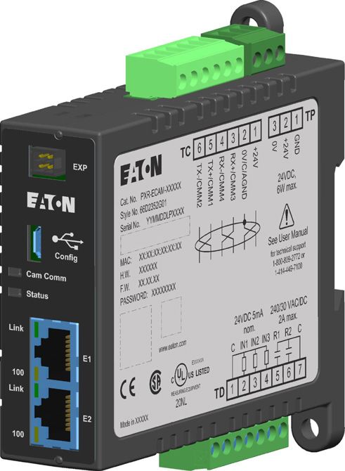
MN012007EN

8 HEALTH MONITOR. . . . . . . . . . . . . . . . . . . . . . . . . . . . . . . . . . . . . . . . . . . . . . . . 33
         8.1 Health Monitor description and function. . . . . . . . . . . . . . . . . . . . . . . . . . . . . . . . 33
         8.2 Health Monitor values. . . . . . . . . . . . . . . . . . . . . . . . . . . . . . . . . . . . . . . . . . . . . . 33
         8.3 Health Monitor Reset procedure. . . . . . . . . . . . . . . . . . . . . . . . . . . . . . . . . . . . . . 34

9 MAINTENANCE OF THE TRIP UNIT. . . . . . . . . . . . . . . . . . . . . . . . . . . . . . . . . . 36
         9.1 Replacing the battery. . . . . . . . . . . . . . . . . . . . . . . . . . . . . . . . . . . . . . . . . . . . . . 36
         9.2 Replacing the ETU. . . . . . . . . . . . . . . . . . . . . . . . . . . . . . . . . . . . . . . . . . . . . . . . 36

10 AVAILABLE PROTECTION SETTINGS. . . . . . . . . . . . . . . . . . . . . . . . . . . . . . . . 36
         10.1 Identifying the trip unit. . . . . . . . . . . . . . . . . . . . . . . . . . . . . . . . . . . . . . . . . . . . 36
         10.2 Detailed settings tables. . . . . . . . . . . . . . . . . . . . . . . . . . . . . . . . . . . . . . . . . . . 38

11 MODBUS REGISTER MAP . . . . . . . . . . . . . . . . . . . . . . . . . . . . . . . . . . . . . . . . 54
         11.1 Viewing/setting Modbus parameters . . . . . . . . . . . . . . . . . . . . . . . . . . . . . . . . . 54
         11.2 Communication protocol. . . . . . . . . . . . . . . . . . . . . . . . . . . . . . . . . . . . . . . . . . . 56
         11.3 Modbus register map. . . . . . . . . . . . . . . . . . . . . . . . . . . . . . . . . . . . . . . . . . . . . 57

iv                   PXR trip units for Power Defense molded case circuit breakers MN012007EN January 2022 www.eaton.com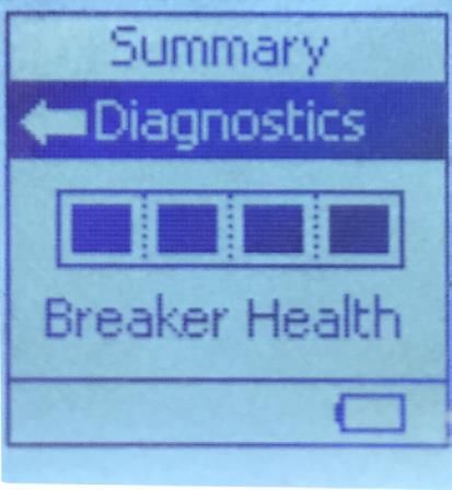
1. Introduction to the Power Xpert® Release trip unit
1. Introduction to the Power Xpert® Release trip unit
The Power Xpert Release (PXR) trip unit has features and flexibility that allow configuration
for a wide variety of protection applications. Communication options support integration
into supervisory systems to monitor performance and, if desired, control the circuit breaker.
Advanced metering of current, voltage, energy and power allow monitoring of real-time
energy use.
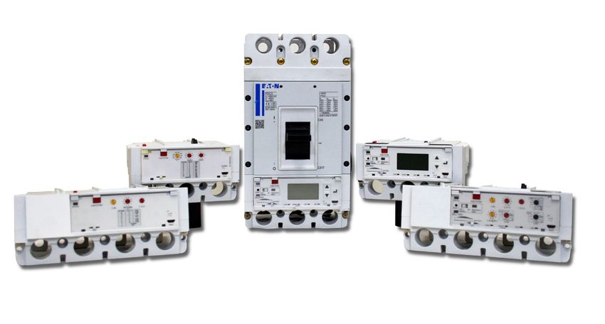
The PXR trip unit is available in multiple models from 15 A (60 A frame) through 2500 A in
MCCBs. All PXR trip units share common features including configuration of their protective
functions, cause-of-trip information, built in secondary injection for testing and a USB port for
connection to configuration and monitoring software. Certain models include energy meter-
ing with 1% accuracy, network connectivity, multi-language display and advanced protection
features.
The PXR trip unit, with its current sensors and a trip actuator, is the subsystem of a circuit
breaker that provides a wide variety of protective functions. The PXR analyzes signals from
the current sensors; if current level and time delay settings are exceeded then the PXR will
trip the circuit breaker. The overload and short circuit tripping characteristics for a specific
circuit breaker are determined by the current rating and user selected protection settings.
Metering uses those same current sensors to monitor and record current. In models that
include voltage metering, a full set of power and energy data is available with 1% accuracy.
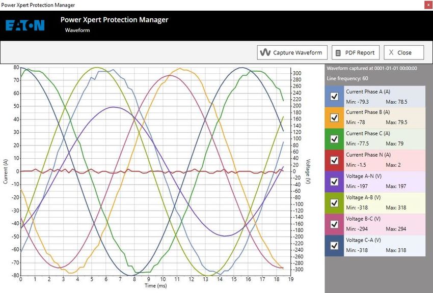
Additionally the PXR supports a waveform capture mechanism by which you can monitor
your systems currents and voltages.
The communication systems provide real-time status and data from the PXR for integration
with business information systems, control schemes or other systems used by service
personnel. The PXR trip units support several field-busses including ModbusRTU, ethernet
Modbus TCP and ProfibusDP. Ethernet communications also includes an advanced web-
interface for use with phone, tablet or PC browsers.
Certain models have a LCD display to make set-up and system monitoring possible from
the face of the MCCB. Other models have rotary switches to set the available protection
settings. Regardless of the interface on the PXR trip units, all aspects of the configuration
and performance are available using PXPM software.
This manual covers the Power Xpert Release family in the Power Defense line of molded
case circuit breakers. Instruction leaflets (IL) are provided with each circuit breaker that
covers the installation. Both this manual and circuit breaker instruction leaflets should be
consulted when applying the PXR trip unit. Please access www.eaton.com/powerdefense
for full details.
1.1 Protection settings overview
The following table shows an overview of protection functionality available in the PXR family
trip units in Power Defense circuit breakers. Detailed information for each trip unit and
circuit breaker are in Section 10: Available protection settings. Note that external control
voltage is not required for protection functionality.
PXR trip units for Power Defense molded case circuit breakers MN012007EN January 2022 www.eaton.com 1
1. Introduction to the Power Xpert® Release trip unit

Line protection settings                            PXR 10                           PXR 20                               PXR 20D and 25                       Units
         Available protection styles                LI                               LSI                                  LSI
                                                    LSI                              LSIG,                                LSIG,
                                                                                     LSI with ARMS                        LSI with ARMS
                                                                                     LSIG with ARMS                       LSIG with ARMS
Overload protection (L)
Ir       Pickup                                     10 settings                      10 settings                          Variable                            Amps
tr       Time delay @ 6 x Ir                        Fixed at 10                      10 settings                          Variable from 0.50                  Seconds
         Time delay slope                           I2t, I4t                         I2t, I4t                             I2t, I4t
         Thermal memory                             Enable/disable                   Enable/disable                       Enable/disable
Short circuit protection (S)
         Enable/disable (OFF position)              Yes                              Yes                                  Yes
Isd      Pickup                                     6 settings 2.0 to 10             9 settings from 1.5                  Variable from 1.5                   x Ir
tsd      Time delay flat                            2 settings 0.15 or 0.30          7 settings from 0.05 to 0.50         Variable from 0.05 to 0.50          Seconds
         Time delay I2t @ 8 x Ir                    0.30                             3 settings 0.07, 0.15, 0.30          Variable from 0.07 to 0.30
         Zone selective interlock                   Not available                    Enable/disable                       Enable/disable with visual
                                                                                                                          indication
Instantaneous protection (I)
Ii       Pickup                                     10 settings                      10 settings                          Variable from 2.0                   x In
Ground (Earth) fault protection (G)
         Enable/disable (OFF position)                                               Enable/disable                       Enable/disable
Ig       Pickup - trip                                                               6 settings from 0.2 to 1.0 (up to    Variable from 0.2 to 1.0 (up to     x In
                                                                                     1200A)                               1200A)
         Pickup - alarm only                                                         3 settings 0.20, 0.50, 1.0           Variable from 0.2 to 1.0 (up to
                                                    Not available                                                         1200A)
tg       Time delay flat                                                             7 settings from 0.10, to 1.0         Variable from 0.10 to 1.0           Seconds
         Time delay I2t @1.0 x In                                                    3 settings 0.07, 0.15, 0.30          Variable from 0.07 to 0.30
         Alarm contact                                                               Optional / configurable              Included / configurable
         Thermal memory                                                              Enable/disable                       Enable/disable
Neutral protection
         4th pole or external neutral trip          3 settings 60% 100% off          3 settings 60% 100% off              3 settings 60% 100% off             x Ir
Maintenance mode protection (ARMS)
         Maintenance mode with visual               Not available                    Local OFF w/ remote enable -or-      Local OFF w/ remote enable
         indication                                                                  local ON                             -or- local ON
         Pickup                                                                      5 settings 2.5, 4.0, 6.0, 8.0, 10    5 settings 2.5, 4.0, 6.0, 8.0, 10   x ln
         Status contact                                                              Optional / configurable              Optional
General
         Cause-of-trip                              Stored in memory                 Stored in memory                     Stored in memory
                                                    Available through PXPM           LED indication                       LED indication
         High load alarm 1 Pickup                                                    85%                                  Variable 50% to 120%                x Ir
         High load alarm 2 Pickup                   Not available                    105%
         High load alarm Contact                                                     Optional / configurable              Configurable
         Temperature trip                           105 °C / 220 °F                  105 °C / 220 °F                      105 °C / 220 °F
Notes:
         Section 9 contains a detailed list of all available settings for each trip unit and breaker frame combination.
         Light gray shaded settings are only configurable through the USB with PXPM software.

2                    PXR trip units for Power Defense molded case circuit breakers MN012007EN January 2022 www.eaton.com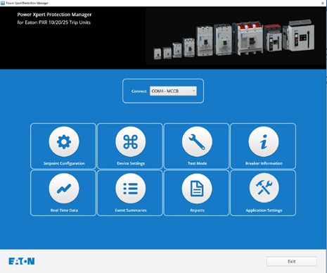
1. Introduction to the Power Xpert® Release trip unit

Motor protection settings                                               PXR 10 -MP                       PXR 25 -MP               Units
Motor overload protection (L)
Ie         Full load amps (FLA)                                         10 settings                      Variable                 Amps
te         Motor trip class                                             5 settings 5 to 30               Variable                 Seconds
                                                                                                         from 5 to 30
           Thermal memory                                               Enable/disable                   Enable/disable
Short circuit protection (S)
I sd       Pickup                                                       10 settings                      Variable                 x Ie
                                                                        3.0 to 13                         from 3 to 13
t sd       Time selay dlat                                              3 settings                       Variable                 Seconds
                                                                        0.05, 0.15 or 0.30               from 0.05 to 0.50
           Zone selective interlock                                     Not available                    Enable/disable
                                                                                                         with visual indication
Instantaneous protection (I)
Ii         Pickup                                                       Fixed                            Variable                 x In
                                                                        (see settings tables)            from 3.0
Ground (earth) fault protection (G)
Ig         Pickup – trip, alarm                                         Not available                    Variable                 x In
           only or OFF                                                                                   from 0.20
tg         Time delay flat                                                                               Variable                 Seconds
                                                                                                         from 0.10 to 1.0
           Thermal memory                                                                                Enable/disable
Motor protection voltage functions
                                    Pickup                               not available                   Variable, 180 to 720     Volts
Over voltage
                                    Time                                                                 Variable, 1 to 300       Seconds
                                    Pickup                               not available                   Variable, 60 to 670      Volts
Under voltage
                                    Time                                                                 Variable, 1 to 300       Seconds
                                    Pickup                               not available                   Variable, 5 to 25        % of Volts
Voltage unbalance
                                    Time                                                                 Variable, 1 to 300       Seconds
                                    Pickup                               variable, 5 to 35               Variable, 5 to 25        % of Amps
Current unbalance
                                    Time                                 variable, 1 to 300              Variable, 1 to 300       Seconds
                                    Pickup                               Yes - use the current           Fixed at 75              % of Amps
Phase loss                                                               Unbalance function
                                    Time                                                                 Variable, 1 to 240       Seconds
                                    Configuration                        Not available                   ABC or CBA               Sequence
Phase rotation
                                    Time                                                                 Fixed at 200             Milliseconds
                                    Pickup                               Not available                   Variable, 1 to 65,500    kW
Reverse power
                                    Time                                                                 Variable, 1 to 300       Seconds
Each function can be set to: a) trip the breaker, b) alarm only, or c) be disabled (OFF)
Neutral protection (N)
                                                                        Described in line protection table above
General protection Functions
        Section 9 contains a detailed list of all available settings for each trip unit and breaker frame combination.
        Light gray shaded settings are only configurable through the USB with PXPM software.

1.1.1 Time current curves
Time current curves (TCC) for every Power Defense circuit breaker within the PXR family of trip units are available at www.
eaton.com/powerdefense.

       PXR trip units for Power Defense molded case circuit breakers MN012007EN January 2022 www.eaton.com                                       3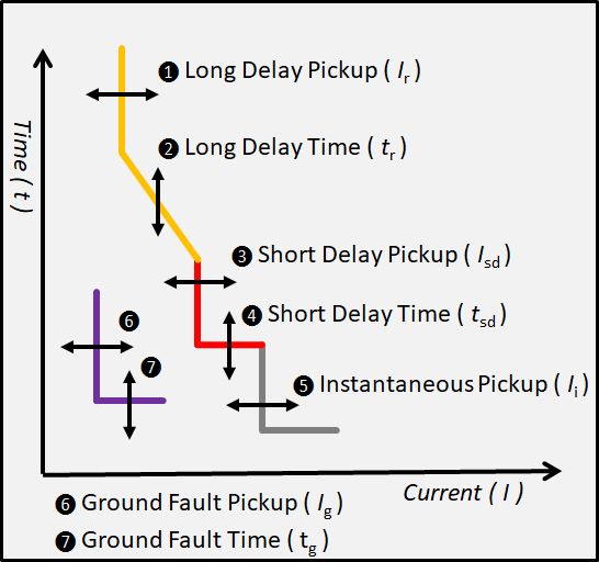
1. Introduction to the Power Xpert® Release trip unit

1.2 Metering features
The following table shows the electrical system information which is metered by the trip
unit. It is available for viewing in PXPM, on the display (if equipped) or for reading via
communication channels.
Metering data                                        PXR 10        PXR 20            PXR 20D          PXR 25
Current                                              *             *                 *                *
Current maximum and minimum                                        *                 *                *
Voltage line to line and line to neutral                                                              *
Voltage maximum and minimum ( L-L and L-N )                                                           *
Power kW (real, demand, peak)                                                                         *
Power kVAR (reactive, demand, peak)                                                                   *
Power kVA (apparent, demand, peak)                                                                    *
Energy kWh (total, fwd, rev) VARh (net), VAh (net)                                                    *
Frequency                                                                                             *
Power factor                                                                                          *

1.2.1 Metered data specifications
Metered data accuracy is as follows:
Metered value       Range of conditions (units)                         PXR 10     PXR 20      PXR 20D      PXR 25
                    5 to 10 % of In (A)                                     na          Na       1.00%        1.00%
Current (I)         10 to 20 % of In (A)                                    na          5.00%    0.50%        0.50%
                    20 to 120% of In (A)                                    5.00%       2.00%    0.50%        0.50%
                    60 to 102 (V)                                                                             1.00%
Voltage (V)         102 to 690 (V)                                                                            0.50%
                    690 to 750 (V)                                                                            1.00%
                    5% to 10% of In (A)                                                                       1.50%
                    102 to 690 (V)
Power (kW)          Power factor = 1
Energy (kWh)        10 to 120 % of In (A)                                                                     1.00%
                    102 to 690 V                                                            na
                    Power factor = 1
                    10 to 20 % of In (A)                                                                      1.50%
                    102 to 690 (V)
Power (kW)          Power factor = 0.5 inductive or 0.8 capacitive
Energy (kWh)        20 to 120% of In (A)                                                                      1.00%
                    102 to 690 (V)
                    Power factor = 0.5 inductive or 0.8 capacitive
Note:               Accuracy is expressed as % of reading, currents are RMS, voltages are RMS line-to-line. Where
                    na trip may report data with a higher lower than 5% accuracy or Zero and should not be used for
                    measuring purposes. All protections will still function as intended..

4                    PXR trip units for Power Defense molded case circuit breakers MN012007EN January 2022 www.eaton.com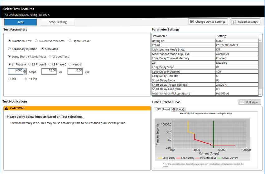
1. Introduction to the Power Xpert® Release trip unit

In addition to the electrical system information metered for line protection, the following data
is available from the motor protection function in the PXR 25 -MP. It is viewed on the display,
in PXPM, or via communication channels.
Metered data                      Description                                                                 Units
Voltage unbalance                 Difference between the maximum and minimum of the 3 voltage readings        Volts
                                  (Vab, Vbc, Vca)
Current unbalance                 Difference between the maximum and minimum of the 3 current readings (Ia,   Amps
                                  Ib, Ic)
Total harmonic distortion (THD)   Voltage, line-to-line (Vab, Vbc, Vca)
                                  Voltage, line-to-neutral (Van, Vbn, Vcn)
                                  Current (Ia, Ib, Ic, In)
Harmonic content
                                                                                                              %
(1st through 35th at 50 Hz)
(1st through 29th at 60 Hz)       Voltage, line-to-line (Vab, Vbc, Vca)
                                  Voltage, line-to-neutral (Van, Vbn, Vcn)
                                  Current (Ia, Ib, Ic, In)

1.3 Health monitor
The PXR 20, 20D, and 25 trip units utilize an innovative algorithm to determine a health
status. The health status is continuously updated as overloads and interruption events
occur. To view the factors that affect the health monitor, select the “Diagnostics” menu.
The summary screen shown below is 100% of life with all four bars shaded. Each bar is
approximately 25% of breaker health according to the algorithm. As the life is decreased, the
shading in the leading bars will disappear. In the PXR 20 the alarm will be generated at 25%
of health remaining. In the PXR 20D and PXR 25 the alarm can be adjusted from 0% - 50%
percent with a default of 25%.

         Summary
        Diagnostics

    Breaker Health

See Chapter 8 Health monitor

       PXR trip units for Power Defense molded case circuit breakers MN012007EN January 2022 www.eaton.com                          5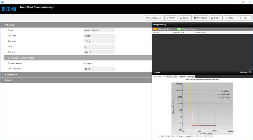
1. Introduction to the Power Xpert® Release trip unit

1.4 Communication features
The PXR 20, 20D, and 25 trip units feature options for built-in communications. Standard
embedded serial communications (optional on the PXR 20) and optional Communications
Adapter Modules (CAM) allow for easy connections over the serial protocol Modbus-RTU,
Ethernet protocols such and Modbus-TCP (CAM), or industrial protocols such as Profibus-DP
(CAM).
The communication features in conjunction with the metering, health, and control functions
can be utilized in IOT based systems, thus allowing for greater visibility in to the facility,
process, or machine, and adhering to the Design Principles of Industry 4.0.

1.5 Control features
The PXR trip units allow for full control of the breaker. This control is available using commu-
nications, discrete I/O or both. This allows the PXR to be easy integrated in to larger control
schemes.
Discrete I/O options for Undervoltage Release (UVRs), Shunt Trips, and relays that can be
configured for a wide range of functions such as trips and alarms, to monitoring of features
like Maintenance Mode or Breaker Health.
Communications capabilities allow options to control even more features, such as the ability
to open the breaker, control configurable relays, enable Maintenance Mode, reset trips,
health, counters, metering and other diagnostic data.

6                PXR trip units for Power Defense molded case circuit breakers MN012007EN January 2022 www.eaton.com
2 PXR user interface

2 PXR user interface
The PXR trip unit interface is common across all frame sizes of the Power Defense family of
circuit breaker frames. This common user interface ensures rapid configuration and makes it
easier to train service personnel. In each frame size, the elements of the interface are easily
recognized even when compressed into smaller fames or mounted horizontally.
The PXR 10 has the simplest user interface (UI), including the essential protection settings
and status. The PXR 20D and PXR 25 have the richest UI, providing setting and operational
information at a glance. Refer to the front panel illustrations of the PXR 10, PXR 20,
PXR 20D and PXR 25 to determine which user interface elements are provided.
There is a setting for the PXR 20D and PXR 25 to rotate the text in the display for breakers
that are mounted horizontally in a panelboard.

2.1 Key interface elements
2.1.1 Status indicator
All PXR trip units have an indicator in the top left labeled “STATUS”. During normal opera-
tion, this indicator blinks green (on and off approximately once each second), indicating that
the trip unit is operating normally.
The status indicator blinks red if the trip unit detects an internal problem. This indicates a
problem with the trip actuator coil, a firmware error, or a mechanism error. Take immediate
action to replace the trip unit or breaker.
When the status indicator remains off, there is no auxiliary power applied or insufficient
primary current to power the trip unit. PXR trip units in MCCB will self-power around
20% of the circuit breaker frame In. For example if a PXR Frame Rating (In) is 60A and
the Long Delay Pickup (IR) is set to 15A the unit will still require 12A ... 20% of 60A to be
self powered. It is recommend to use Aux power if lower power levels are normal, this will
insure that non-protection oriented features such as communication, status indicator and
display remain functional.

2.1.2 USB – test and configuration port
The lower right corner of all PXR trip units has a standard micro-B USB connector. PXPM
software uses the USB port to configure, test and monitor the trip unit. Download the
installation package for PXPM software from www.eaton.com/pxpm.
A USB cable connection from a host PC will power the trip unit when the trip unit is
not harvesting sufficient energy from the mains or there is no auxiliary power applied.
Commercially available battery packs can also power the trip unit. This connection is
intended for temporary use while a user is configuring, monitoring or testing the trip unit.

2.1.3 Pickup/cause-of-trip indicators
All PXR family trip units record the cause-of-trip (CoT) in memory. The CoT is available by
using PXPM software and via the communication networks.
There are four pickup/cause-of-trip indicators labeled “LONG”, “SHORT”, “INST”, and “GND”
on all except the PXR 10. The appropriate indicator blinks when a current level pickup
setting is exceeded. After a trip event, the appropriate indicator flashes (0.25 second on,
three seconds off) and is annunciated on the display.
•   “LONG”      – Long delay or over temperature
•   “SHORT”     – Short delay
•   “INST”      – Instantaneous, override or maintenance mode
•   “GND”         –        Ground fault
2.1.4 Reset
The button labeled “RESET” can be pressed using a small tool. When pressed, it clears the
cause-of-trip indicators, clears any latched alarms on the configurable relays and clears the
ZSI “check mark” on the display (illuminates after a ZSI input signal is detected).

      PXR trip units for Power Defense molded case circuit breakers MN012007EN January 2022 www.eaton.com            7
2 PXR user interface
2.1.5 Battery
For PXR units, which have cause-of-trip indicators, within the trip unit is a small tray that
holds the battery. The battery supports the cause-of-trip indicators for 20 days when the
trip unit is not powered. The battery plays no part in the protection functions of the trip
system. On the initial installation of the circuit breaker, remove and discard the insulating
tab to enable the battery. This battery is a standard CR type “coin-cell”, for replacement use:
CR1216. The battery also holds the power for the real time clock chip for time and date infor-
mation. After replacing the battery, the time and date should be reprogrammed.
The “RESET” button can be pressed and held for two seconds to test the battery. If OK,
the “LONG” LED will illuminate green, if the battery should be replaced it will illuminate
yellow, and if the battery is either low or missing it will blink yellow. For PXR 20D and PXR
25 the battery status is also indicated in the lower right corner of the display.
2.1.6 High load indicator
On the PXR 20D and PXR 25, the indicator labeled “Alarm1/Alarm2” (high-load indicator) is
illuminated yellow based on the configured load setting. The LED will be solid when above
the high load warning (Alarm1) pickup, and the LED will blink when above the high load
alarm (Alarm2) pickup. Note that high load alarm (Alarm2) (blink) takes precedence over high
load warning (Alarm1) (solid).
On the PXR 20, the indicator labeled “85%Ir/105%Ir” (high-load indicator) is illuminated
yellow based on fixed setting. The LED will be solid when above the the 85% of Ir fixed
load setting, and the LED will blink when above the 105% of Ir fixed load setting. Note that
fixed laod setting 105% Ir (blink) takes precedence over fixed load setting 85% Ir (solid).
2.1.7 Maintenance Mode switch
When supplied, the PXR trip unit incorporates the Arc Flash Reduction Maintenance
System™. The switch is labeled “Maintenance Mode” and has two positions labeled “OFF/
Remote” and “ON”. A blue light next to the Maintenance Mode switch illuminates when the
Arc Flash Reduction Maintenance System protection is enabled.
• “ON” – Arc Flash Reduction Maintenance System is enabled locally and cannot be
disabled remotely
• “OFF/Remote” – Arc Flash Reduction Maintenance System is OFF, or can be remotely
controlled by a dry contact, communications or PXPM. See Section 3.6: Maintenance
Mode protection for complete details
2.1.8 Push to trip
A red button on the front of the trip unit or circuit breaker provides a mechanical means of
tripping the circuit breaker. Use a small tool to depress it and trip the breaker mechanism.
2.1.9 Tamper proof cover
A clear plastic cover allows the settings to be viewed but not changed. Controlling physical
access is a key element in your comprehensive security policy. Unauthorized access to
change settings is prevented by insertion of a standard sealing wire through the security
holes in order to meet applicable tamper-proof requirements.
2.1.10 Password security
Protecting your system from cyber security threats is very important. In addition to the
tamper-proof cover, PXR trip units have a four-digit password used to secure certain settings
and to enable secondary injection testing. To change a setting, which is not set by a physical
switch, will require you to enter the four-digit password. Authorization to make changes will
timeout after 10 seconds of inactivity. Password security is also enforced when using the
display, PXPM software and when another device attempts a change via a communication
network.
Changing the factory default password is a key element of a comprehensive cyber security
policy. From the factory the default is ‘0-0-0-0’. Upon installation of the PXR, the password
should be changed (under the settings menu) and only made available to those individuals
who require it.
8 PXR trip units for Power Defense molded case circuit breakers MN012007EN January 2022 www.eaton.com2 PXR user interface
For additional information and cyber security best practices, please go to www.eaton.com/
cybersecurity. Detailed guidance is under the “Documentation” tab on this cybersecurity
home page.
2.1.11 Catalog number and In rating
Trip unit family and protection functionality are printed in the upper right of the front panel.
The rated In values are printed near the test port. The catalog number is also printed on the
front, it starts with “PD” and the last three digits define the factory configuration options.
See Section 10.1: Identifying the trip unit for a full list of options.
2.1.12 QR code
The 2D barcode (QR code) on the front of each trip unit encodes the trip unit catalog and
serial number. This can be used to look-up product information that is available on-line from
Eaton.
PXR 25, PXR 25 Motor Protection, and 20 D display with keypad
2.2 PXR 25, PXR 25 Motor Protection, and 20D display with keypad
The PXR 20D and PXR 25 user interface (UI) has a display and keypad on the front of the trip
unit. This display provides information regarding the operation of the trip unit and the
method to select configuration options. The keypad provides for navigation through the
menu structures. Information is presented on the display in English, Chinese, German,
Spanish, or up to two additional languages (loaded by PXPM). To provide for easier reading
of the display with the circuit breaker mounted on its side, the display is configurable to
rotate 90 degrees left or right.
There are three navigation buttons near the
display used to control the information shown Events Menu title
on the display and to select configuration
options: Main Menu
Example of a
Events
Summary highlighted field
Up arrow button - Used to move up in
Trip
the menu display screen or increase an Battery life
adjustment value. Alarm indicator
Down arrow button - Used to move ZSI
down in the menu screens or decrease Indicates menu
an adjustment value. fields above or
ZSI indicator below the
Enter button - Used to enter a menu or
highlighted field
configuration setting or to go back to the
previsions menu.
Each trip unit style has configurable settings for protection and other features. They can
be configured using either the front panel or by using PXPM software. Details regarding
the available protection settings for each frame are found in Section 9: Available protection
settings.
PXR trip units for Power Defense molded case circuit breakers MN012007EN January 2022 www.eaton.com 92 PXR user interface
When the PXR trip unit is initially powered-up, the display will briefly show a loading screen
and then change to the main menu. During this time, the trip unit is already functioning
and performing protection operations. Depending on the trip unit style, there are up to 12
submenu selections from the main menu.
Each is accessed by pressing the down arrow or up arrow buttons to highlight the appropri-
ate submenu, then pressing the enter button
Back lighting is included on the display with a power saver feature that after two minutes of
inactivity will extinguish the backlight. In addition, after 20 minutes of inactivity, the display
will enter an idle-screen mode that scrolls through the most important status information
and settings. Pressing any button will light the backlight and, if active, stop automatic scroll-
ing, allowing you to navigate the menu structure. With the tamper-proof cover secured,
only the up arrow and down arrow buttons are accessible, pressing either will light the
PXR backlight,
20 with rotary
stopswitches
the automatic scrolling and allow you to navigate and view status and setting
information.
2.3 PXR 20 with rotary switches
Depending on the trip unit style, up to seven rotary switches can be found on the trip unit’s
front panel. The switches are color-coded and set protection settings using a surrounding
legend indicating the value of that setting. These are the core protection settings, other
configurable settings can be set using PXPM. Details regarding the available protection
settings for each frame are found in Section 9: Available protection settings.
Each switch has ten positions and is set to achieve the appropriate trip-curve response.
The yellow color switches set the overload configuration, red switches set the short circuit
behavior and grey switches set the ground fault behavior. The “PICKUP” switches set
the levels as a function of the breaker ratings. The “TIME” switches set the response
in seconds.
PXR 10 simplified rotaryEach switch can be set using a small screwdriver, the arrow pointing to the
switches
selected value.
2.4 PXR 10 simplified rotary switches
The PXR 10 trip curve configuration is simple, using the switches on the front panel. LSI trip
units have three rotary switches, while the LI version has only two, eliminating the center
“SD Profile” switch. For all, the yellow color rotary switch sets the Ir and the red switches
define short circuit behavior. Details regarding the available protection settings for each
frame are found in Section 9: Available protection settings.
10 PXR trip units for Power Defense molded case circuit breakers MN012007EN January 2022 www.eaton.com3 Protection setting description
PXR 10 Motor Protection simplified rotary switches
2.5 PXR 10 motor protection simplified rotary switches
The PXR 10 motor protection trip curve configuration is simple, using the switches on the
front panel. MLSI trip units have three rotary switches. The yellow color rotary switch sets
the full load amps FLA Ie (A) and the red switches trip profile and Instantaneous lsd(X le).
Details regarding the available protection settings for each frame are found in Section 9:
Available protection settings.
3 Protection setting description
The PXR trip unit protection settings are easily customized to any application. Settings
for long delay pickup, long delay time, short delay pickup, short delay time, instantaneous
pickup, ground fault pickup, and ground fault time are all configurable. These functions are
set using PXPM software, or rotary switches or the UI on the front of the trip unit.
Maximum and minimum settings will vary by trip unit style and breaker frame. A summary
of the available settings by PXR model and breaker frame is shown in Section 1.1, please
consult the detailed tables within Section 9: Available protection settings.
Before placing any circuit breaker in operation, set each trip unit protection setting to the
values specified by the engineer responsible for the installation.
3.1 Long delay pickup and time setting
The PXR trip unit offers a wide range of settings for long delay pickup (LDPU or Ir). The
actual pickup value for long delay will be 110% of the set point value with a +/- 5% tolerance
to ensure that the circuit breaker can carry the full rating of (Ir), without tripping.
The long delay time setting value represents the clearing times when the current value
equals six times (Ir). All times are referenced from the top of the tolerance band, ensuring
that the time never exceeds that maximum setting.
Ir is also the base for the short delay current setting.
PXR trip units for Power Defense molded case circuit breakers MN012007EN January 2022 www.eaton.com 113 Protection setting description
3.1.1 Long delay slope selection
The I2t setting is the factory default curve for long delay. Certain styles of trip unit offer
other slope selections. The curve can be changed using PXPM software or the UI to better
match application requirements for protection and coordination.
• I2t - Inverse time current curve, used in standard distribution protection (factory default).
• I4t - Extremely inverse time current curve, for coordination with fuses or special types of
loads.
3.1.2 Long delay thermal memory
In addition to the standard long delay protection, a long time memory (LTM) function is
supported. This protects load circuits from the effects of repeated overload conditions.
LTM is enabled from the factory but can be reconfigured using the UI or by using PXPM
software.
As an example, if a circuit breaker is closed soon after a long delay trip, and the current
again exceeds the long delay setting (Ir), the LTM automatically reduces the time to trip to
allow for the fact that the load conductor temperature is already higher than normal because
of the prior overload condition. When the load current returns to normal, below pickup, the
LTM will begin to reset (after about ten minutes it will have reset fully) so the next long
delay trip time will again correspond to cold start on the curve. In certain applications and
when doing repetitive field testing, it may be desirable to disable the LTM function.
3.2 Short delay pickup and time settings
Settings for short delay pickup (SDPU or Isd) are expressed as multiples of the long delay
pickup current setting (Ir).
The short delay time (tsd) is selected in conjunction with one of two short delay slopes, flat,
or I2t. The I2t response curve will provide a longer time delay for currents below eight times
Ir as compared with a flat response curve. For currents greater than eight times Ir, the I2t
response reverts to a flat response.
The optional zone selective interlocking (ZSI) feature may affect the tripping times for the
short delay protective function. Please refer to the section on ZSI.
3.3 Instantaneous pickup setting
The instantaneous (Ii) setting is expressed as multiples of the circuit breaker frame rating
(In). The instantaneous protection trips the breaker with no intentional time delay.
3.4 Ground fault settings
When the PXR 20, 20D or 25 trip unit includes ground fault protection features, the distribu-
tion system characteristics (such as system grounding, number of sources, and number
and location of ground points) must be considered along with the manner and location in
which the circuit breaker is applied to the system. To ensure correct ground fault equipment
performance and compliance, you must conduct the field testing required to comply with
country or regional requirements.
3.4.1 Ground fault pickup
The PXR trip unit provides flexibility in detecting and acting on ground currents. A ground
fault alarm can provide an early warning of a ground fault condition and a ground fault trip
can provide protection under these conditions. Three modes of operation are selectable
from the front of the trip unit.
• The ground detection may be turned off by selecting “OFF”.
• The ground fault detection pickup level with an alarm only action can be used by selecting
“Alarm”. Multiple levels of pickup are available depending on the trip unit style.
• The ground fault detection pickup level with an action of trip may also be used by selected
“Trip”. If a ground fault causes the circuit breaker to trip.
12 PXR trip units for Power Defense molded case circuit breakers MN012007EN January 2022 www.eaton.com3 Protection setting description
3.4.2 Ground fault time
The PXR trip unit provides selection for two different ground fault slopes: a fixed time (flat)
or I2t response. The slope should be chosen to match coordination needs. The I2t slope
response provides a longer time delay for coordination of currents below 1.0 x In frame.
After 1.0x the response reverts to a fixed time (flat) response. The time delay and slope are
selected using PXPM or the user interface (UI).
3.4.3 Ground fault thermal memory
In addition to standard ground fault protection, the PXR trip unit also has a ground fault
memory. This protects load circuits from the effects of intermittent ground faults over a
short period of time. Ground fault memory is enabled from the factory but can be reconfig-
ured using the UI or by using PXPM software.
Consider an example where there is “sputtering” ground fault. With ground fault memory,
the trip unit “remembers” the sputtering ground current. When the ground current returns
to normal, below pickup, the memory will begin to reset (after about ten minutes it will have
reset fully). The next ground trip time will again correspond to the curve. Without this func-
tion enabled, ground fault protection memory resets each time the arc goes out, so that a
sputtering fault may not trip the circuit breaker.
3.4.4 Ground fault relay
If the ground fault alarm option is selected, a red ground alarm indicator will illuminate to
show the presence of ground current in excess of the ground alarm setting. The optional
relays in the trip unit can be configured to energize an alarm relay upon this condition. The
indicator and relay will reset automatically when the ground current reduces to a value less
than the ground fault pickup setting.
If the ground fault trip option is selected, the trip unit can indicate when the circuit breaker
has tripped on a ground fault. You must then push the “RESET” button in order to reset the
relay contact.
3.4.5 Ground fault sensing
The PXR 20/25 trip unit provides for three modes of sensing to detect ground fault currents:
residual, source ground, and zero sequence. The mode is selected using the UI or by using
the configuration software.
See Section 3.5: Special consideration for ground fault test for guidance when testing
ground fault functionality.
Residual current sensing
Residual sensing is the standard mode of ground fault sensing in PXR based circuit break-
ers. This mode uses one current sensor on each phase conductor and one on the neutral
for a four-wire system. If the system neutral is grounded, but phase to neutral loads are not
used, the PXR trip unit includes all of the components necessary for ground fault protection.
This mode of sensing sums the outputs of the three or four individual current sensors. If
the sum is zero, then no ground fault exists. Residual ground fault sensing features are
adaptable to main and feeder circuit breaker applications. If an external neutral sensor is
used with reverse feed breaker applications, the proper polarity of the neutral needs to be
considered.
Source ground / zero sequence sensing
These two methods are only available on Power Defense frames five and six. The source
ground return method is usually applied when ground fault protection is desired only on
the main circuit breaker in a simple radial system. This method is also applicable to double-
ended systems where a mid-point grounding electrode is employed.
For this mode of sensing, a single current sensor mounted on the equipment-bonding
jumper will directly measure the total ground current flowing in the grounding electrode
conductor. Setting the ground fault type will enable this protection.
PXR trip units for Power Defense molded case circuit breakers MN012007EN January 2022 www.eaton.com 133 Protection setting description
Zero sequence sensing also referred to as vectoral summation, available in certain styles, is
applicable to mains, feeders, and special schemes involving zone protection.
Ground (Earth) sensing method Frame Sensor catalog #
PD2 – 60, 63, 100 Amp w/o bus-bar PDG2XNCTD0100
PD2 – 150, 160, 200, 225, and 250 Amp w/o bus-bar PDG2XNCTD0225
PD2 – 60, 63,100 Amp for cable PDG2XNCTB0100
PD2 – 150, 160, 200, 225, and 250 Amp for cable PDG2XNCTB0225
Residual
PD3 for bus-bar PDG3XNCTB0600
PD4 for bus-bar PDG4XNCTB0800
PD5 for bus-bar PDG5XNCTB1200
PD6 for bus-bar PDG6XNCTB2500
Source ground / zero sequence PD5 and PD6 Tbd
3.4.6 Special consideration for ground fault test
3.4.6.1 NEC requirements and UL standards
The National Electric Code (NEC) under Article 230-95-C requires that any ground-fault
protection system be performance tested when first installed. UL Standard 489 amd 1053
specify that instructions for ground fault testing accompany each ground fault protection
system. Please consult Instruction leaflet number IL012125EN available at www.eaton.com/
powerdefense to aid you in ground fault testing the Power Defense circuit breaker.
3.5 Motor Protection settings description
The PXR trip unit motor protection settings are easily customized to any application.
Available protection features and specific settings will vary by trip unit style and breaker
frame. Before placing any circuit breaker in operation, set each trip unit protection setting to
the values specified by the engineer responsible for the installation.
Overload and short circuit protection setting details for each trip unit and frame combination
are found in in section 9 - Detailed Protection Settings.
Overload Protection
Protection of motor loads is accomplished by the trip unit determining when a motor is
drawing currents over its rated current. An overload is a condition in which currents above
the rated value are present, but unlike a fault current, overloads may be of just a few
amperes over the rated current. Nevertheless, overloads can cause irreversible damage due
to the amount of heat released. Overload protection has a time delay. This has the purpose
of allowing short-duration overcurrent conditions, which are normal in the operation of some
types of equipment.
Short Circuit & Instantaneous Protection
Protection against short circuits and instantaneous is the same as line protection. Both can
be configured to meet a wide variety of motor protection applications.
Motor Protection Specific Functions
Motor protection circuit breakers include additional protection features which can be used to
protect equipment during certain system events, such as under/over voltage (sag/swell) and
phase current anomalies. See the table Additional Motor Protection Settings. The protection
functions have set points and/or time delays which should be matched to the specific needs
of the load. Each protection function is configured by accessing the menu system using the
LCD and buttons or by using Eaton’s Power Xpert Protection Manager software (PXPM).
14 PXR trip units for Power Defense molded case circuit breakers MN012007EN January 2022 www.eaton.com3 Protection setting description
Protection Function Actions
The protection functions can also be configured to take one of 3 actions;
1. Trip the breaker with alarm
2. Alarm only, do not trip
3. Be totally disabled
Hint: On the PXR25 LCD, use Main Menu > Settings > Motor > Feature to set one of the
3 actions. Or in PXPM for both the PXR 10 and PXR 25, use the drop-down menus
under the setpoint configuration.
Protection Function: Over Voltage
Line-to-line RMS voltages (Vab, Vbc, Vca) are continuously monitored. If any line-to-line
voltage is greater than the pickup setpoint for the specified time delay, then the configured
protection action will be taken.
Protection Function: Under Voltage
If any line-to-line voltage is less than the pickup setpoint for the specified time delay, then
the configured protection action will be taken.
Note: Setpoint ranges for under voltage and overvoltage overlap. If both are used in an
application, under voltage pickup should always be set less than over voltage pickup.
If under voltage pickup is set higher than overvoltage pickup and the breaker is
closed, the trip unit will see one or both conditions pickup satisfied, begin timing and
trip.
Protection Function: Voltage Unbalance
If the difference between the maximum and minimum of any of the 3 line-to-line voltages
is greater than the pickup for the specified time delay, then the configured protection action
will be taken. Action will be taken only when at least one line-to-line voltage is greater than
84 V.
Max(Vab,Vbc,Vca)-Min(Vab,Vbc,Vca)
The calculation for the voltage unbalance pickup is: x 100%
Max(Vab,Vbc,Vca)
Max
x(Vab,Vbc,Vca)
Protection Function: Current Unbalance
The RMS current in each of the phases (Ia, Ib, Ic) is continuously monitored. Unbalance
protection will protect against partial or full loss of one or two phases. If the difference
between the maximum and minimum of any of the 3 phase currents is greater than the
pickup for the specified time delay, then the configured protection action will be taken. The
Long Delay indicator on the front panel will illuminate. Action will be taken only when at
least one phase current is greater than 50% of the FLA setting (0.5 x Ie ).
Max(Ia,Ib,Ic)-Min(Ia,Ib,Ic)
The calculation for the current unbalance and phase loss pickup is: x 100%
Max(Ia,Ib,Ic)
Protection Function: Phase Loss
Phase loss protection is used for complete loss of one or two phases. If the difference
between the maximum and minimum of any of the 3 phase currents is greater than 75%,
for the specified time delay, then the configured protection action will be taken. Action will
be taken only when at least one phase current is greater than 50% of the FLA setting
(0.5 x Ie ).
Protection Function: Phase Rotation
The phase relationship of the line-to-line voltages is continuously monitored. If the phase
sequence is different from the setting, then after the fixed time delay, the configured protec-
tion action will be taken. Action will be taken only when at least one line-to-line voltage is
greater than 84 V.
PXR trip units for Power Defense molded case circuit breakers MN012007EN January 2022 www.eaton.com 153 Protection setting description
Protection Function: Reverse Power
Power flowing through the breaker is continuously monitored. If the reverse real power is
greater than the pickup for the specified time delay, then the protection action will be taken.
3.6 Maintenance Mode protection
The PXR trip units support Eaton’s Arc Flash Reduction Maintenance System, also known
as Maintenance Mode. When maintenance is being performed and the Arc Flash Reduction
Maintenance System is enabled, the trip unit will trip the breaker with no intentional delay
whenever the configured pickup level is exceeded. The Maintenance Mode protection over-
lays the LSI protection functions and operates in parallel. If Maintenance Mode causes the
circuit breaker to trip, the “INST” indicator will be illuminated and the “Maintenance Mode
Trip” message will be displayed if the style of trip unit has a display. A verification check
of the remote Arc Flash Reduction Maintenance System feature is recommend as part of
standard work practices relating to maintenance / service of electrical equipment that incor-
porates circuit breakers with remote Arc Flash Reduction Maintenance System feature.
The Maintenance Mode pickup level setting is configured using the UI or PXPM software.
They range from 2.5 (most protective) to 10, expressed as a multiplier of In. The adjustable
current settings allow for different levels of protection. A higher level may be needed when,
for example, another load fed from the Arc Flash Reduction Maintenance System protected
breaker may contain motors that are being started and create large inrush currents over the
lowest trip current level. The selection of one of the reduction settings should be deter-
mined and selected by a person who is experienced in power system analysis.
3.6.1 Actuating and indicating Maintenance Mode protection
There are three ways to actuate the Maintenance Mode function, locally, remotely using a
contact, or remotely using communications. A blue LED on the trip unit always illuminates
to confirm when the function is enabled.
• For locally actuating the Maintenance Mode function, use the slide switch on the front
of the trip unit. When in the “ON” position, Maintenance Mode is enabled locally and
cannot be turned-off remotely or by communications. This method does not require auxil-
iary power to the trip unit, and the blue LED on the face of trip unit will light when the trip
unit is self-powered.
• Maintenance Mode can be remotely actuated by an external contact wired to the breaker
when the local switch is in the “OFF/Remote” position. See Section 5.1: Wiring table
for details regarding the contact and wiring length. When Maintenance Mode is enabled
by an external contact, it must also be disabled via the external contact. Moving the
local switch from “OFF/Remote” to “ON” and back to “OFF/Remote” will not disable
Maintenance Mode. Auxiliary power (24 V DC) is required for Maintenance Mode remote
activation
• A third method to actuate Maintenance Mode is via communications. This can be done
through a modbus register, a communications adapter module (CAM) or by the configura-
tion software using the USB port. When Maintenance Mode is enabled by communica-
tions, it must also be disabled via communications. Moving the local switch from “OFF/
16 PXR trip units for Power Defense molded case circuit breakers MN012007EN January 2022 www.eaton.com3 Protection setting description
Remote” to “ON” and back to “OFF/Remote” will not disable Maintenance Mode.
Auxiliary power (24 V DC) is required for communications functionality, including mainte-
nance mode remote activation.
Any of the configurable relay contacts can be used to remotely indicate when Maintenance
Mode is active. Auxiliary power (24 V DC) is required for the remote indication via a relay
contact.
3.7 Override
The PXR trip unit provides an override trip function that will trip the circuit breaker at the
withstand rating of the circuit breaker frame. This function is factory set and reacts to the
peak current level. It is always active regardless of the user’s instantaneous adjustment
selection. The instantaneous (“INST”) indicator shows this cause-of-trip.
3.8 Zone selective interlocking (ZSI)
The zone selective interlocking (ZSI) function is an option when ordering the circuit breaker.
ZSI functions in conjunction with the short delay and ground fault protection functions. ZSI
provides the fastest possible tripping for faults within the zone of protection of the circuit
breaker and also provides positive coordination among all circuit breakers in the system
(mains, ties, feeders, and downstream circuit breakers). Application note (AP02602002E) is
available and has additional detail.
When ZSI is enabled, a fault within the zone of protection will immediately trip the breaker
and send a signal to upstream trip units to restrain them from tripping immediately. The
restraining signal causes the upstream circuit breakers to follow their set coordination time
delays so that the service is interrupted to the isolated fault area only while the fault is
cleared in the shortest time possible.
The ZSI is wired using a set of three wires labeled zone in (Zin), zone out (Zout), and zone
common (Zcom). These signals are compatible will all Eaton circuit breakers which have
the ZSI function. The zone out signal is sent whenever a ground fault pickup or short delay
pickup is exceeded. This provides maximum selectivity for coordination with larger upstream
circuit breakers.
ZOUT
ZIN
ZCOM
breaker
zone 1
ZOUT ZOUT
ZIN ZIN
ZCOM ZCOM
breaker breaker
zone 2
ZOUT ZOUT ZOUT
ZIN ZIN ZIN
ZCOM ZCOM ZCOM
breaker breaker breaker
zone 3
typical Zone Selective Interlock wiring
Motor protection circuit breakers are used in the final breaker (lowest zone) in a complete
ZSI enabled system. The zone out (Zout) signal is sent whenever a short circuit delay protec-
tion or ground fault protection pickup is exceeded. This indicates to the circuit breaker in
PXR trip units for Power Defense molded case circuit breakers MN012007EN January 2022 www.eaton.com 174 Communication functionality
the zone above that the fault has been seen and will be acted upon. For all motor protection
circuit breakers, the zone in (Zin) signal is not used.
ZSI in the PXR trip unit is fully compatible with ZSI in the Digitrip for Magnum, Digitrip for
NRX, OPTIM and 310+ Series C and Series G trip units. If a PXR trip unit has the ZSI option
but it is not needed in an application, it may be disabled using the Power Xpert Protection
Manager software or the menus on the UI, or the Zout and Zin may be connected to “self-
interlock” the unit.
ZOUT
ZIN
ZCOM
breaker
ZOUT ZOUT ZOUT
ZIN ZIN ZIN
ZCOM ZCOM ZCOM
MP MP MP
breaker breaker breaker
motor motor motor
Zone Selective Interlock - showing Zin on
the Motor Protection Breakers not used
PXR trip units with a display have a visual indication of the ZSI system being active and
connected to the other breakers in the ZSI system. A small check-mark will appear next to
the ZSI when the trip unit receives a ZSI-IN signal. The general-purpose, configurable, relay
contacts may also be programmed to indicate ZSI signals and status.
3.9 Operating temperature
All models of trip units are designed for commercial/industrial circuit breaker environments.
The frames are rated for load and temperature per individual circuit breaker. As an additional
protection, if temperatures in the PXR trip-unit exceed 105 °C (220 °F), a factory-set over-
temperature protection feature will trip the circuit breaker to protect the internal electronic
components.
4 Communication functionality
The PXR family of trip units offers wide support for communications. A USB port is present
on all PXR family trip units. All PXR 20, 20D and 25 support external communication adapter
modules (CAM) while certain models have built-in Modbus-RTU.
4.1 Integrated Modbus - remote terminal unit (RTU)
A Modbus communication port is integrated into the PXR trip unit for certain styles. Breaker
status (closed/tripped/open), set points and operating information are all available via
Modbus. The trip unit responds to messages from the master using the remote terminal
unit (RTU) protocol. Modbus port configuration can be viewed and set using the user
interface (UI) or using Power Xpert Protection Manager software. The trip unit uses Modbus
function codes 02, 03, 04, 06, 08, and 16 and supports up to 122 registers (244 bytes) in a
single Modbus transaction.
The detailed Modbus register map is shown in Section 10: Modbus communication port
register map. Auxiliary power (24 V DC) is required for integrated Modbus communications
18 PXR trip units for Power Defense molded case circuit breakers MN012007EN January 2022 www.eaton.com4 Communication functionality
4.2 USB port
The PXR includes a micro-B form USB port on the front of the trip unit. This USB connection
is used in conjunction with your PC running the PXPM software to configure, control, and
test the trip unit. The USB host-side also supplies power to the electronics for configuration
when the circuit breaker is not carrying current or when no auxiliary power is applied and for
trip unit testing (both trip and no-trip). A commercial USB battery supply may also be used.
The USB port is covered by the clear, lockable cover to prevent unauthorized modification to
settings. Controlling physical access to the USB port is a key element in your comprehen-
sive cyber security plan.
4.3 External communications adapter modules (CAMs)
The PXR 20, 20D and 25 trip units are equipped to handle a flexible and modular system of
communication adapter modules (CAMs). These modules provide communication from the
trip unit to a field bus network. These modules mount on a DIN rail and wired into the trip
unit. Auxiliary power (24 V DC) is required for CAM module communications.
The following networks are supported at the time of manual publication:
Network Module name Instruction leaflet Wiring harness
ETHERNET (Modbus TCP) PXR-ECAM – MTCP IL0131132EN Field wired
PROFIBUS PXR-PCAM IL120009EN Field wired
Please consult the respective instruction leaflet for details.
Please visit www.eaton.com/powerdefense and search for communications adapter modules
for current offerings.
PXR trip units for Power Defense molded case circuit breakers MN012007EN January 2022 www.eaton.com 19You can also read