MSR55P Back EMF Minotaur Safety Relay - User Manual - Literature ...

Page created by Dana Daniel
 
CONTINUE READING
MSR55P Back EMF Minotaur Safety Relay - User Manual - Literature ...
MSR55P Back EMF Minotaur
  Safety Relay
  Catalog Numbers 440R-S35011, 440R-S35012, 440R-S35013,
  440R-S35014, 440R-S35015, 440R-S35016

User Manual                              Original Instructions
MSR55P Back EMF Minotaur Safety Relay - User Manual - Literature ...
MSR55P Back EMF Minotaur Safety Relay User Manual

Important User Information
Read this document and the documents listed in the additional resources section about installation, configuration, and
operation of this equipment before you install, configure, operate, or maintain this product. Users are required to familiarize
themselves with installation and wiring instructions in addition to requirements of all applicable codes, laws, and standards.

Activities including installation, adjustments, putting into service, use, assembly, disassembly, and maintenance are required to
be carried out by suitably trained personnel in accordance with applicable code of practice.

If this equipment is used in a manner not specified by the manufacturer, the protection provided by the equipment may be
impaired.

In no event will Rockwell Automation, Inc. be responsible or liable for indirect or consequential damages resulting from the use
or application of this equipment.

The examples and diagrams in this manual are included solely for illustrative purposes. Because of the many variables and
requirements associated with any particular installation, Rockwell Automation, Inc. cannot assume responsibility or liability for
actual use based on the examples and diagrams.

No patent liability is assumed by Rockwell Automation, Inc. with respect to use of information, circuits, equipment, or software
described in this manual.

Reproduction of the contents of this manual, in whole or in part, without written permission of Rockwell Automation, Inc., is
prohibited.

Throughout this manual, when necessary, we use notes to make you aware of safety considerations.

              WARNING: Identifies information about practices or circumstances that can cause an explosion in a hazardous environment,
              which may lead to personal injury or death, property damage, or economic loss.

              ATTENTION: Identifies information about practices or circumstances that can lead to personal injury or death, property
              damage, or economic loss. Attentions help you identify a hazard, avoid a hazard, and recognize the consequence.

    IMPORTANT        Identifies information that is critical for successful application and understanding of the product.

These labels may also be on or inside the equipment to provide specific precautions.

              SHOCK HAZARD: Labels may be on or inside the equipment, for example, a drive or motor, to alert people that dangerous
              voltage may be present.

              BURN HAZARD: Labels may be on or inside the equipment, for example, a drive or motor, to alert people that surfaces may
              reach dangerous temperatures.

              ARC FLASH HAZARD: Labels may be on or inside the equipment, for example, a motor control center, to alert people to
              potential Arc Flash. Arc Flash will cause severe injury or death. Wear proper Personal Protective Equipment (PPE). Follow ALL
              Regulatory requirements for safe work practices and for Personal Protective Equipment (PPE).

The following icon may appear in the text of this document.

          Identifies information that is useful and can help to make a process easier to do or easier to understand.

2                                        Rockwell Automation Publication 440R-UM014H-EN-P - March 2022
Table of Contents

                                 Preface
                                 Who Should Use This Manual . . . . . . . . . . . . . . . . . . . . . . . . . . . . . . . . . . . . .                      5
                                 Download Firmware, AOP, EDS, and Other Files . . . . . . . . . . . . . . . . . . . .                                      5
                                 Summary of Changes. . . . . . . . . . . . . . . . . . . . . . . . . . . . . . . . . . . . . . . . . . . . .               5
                                 Definitions . . . . . . . . . . . . . . . . . . . . . . . . . . . . . . . . . . . . . . . . . . . . . . . . . . . . . .   5
                                 Additional Resources . . . . . . . . . . . . . . . . . . . . . . . . . . . . . . . . . . . . . . . . . . . . .            6

                                 Chapter 1
Overview                         Safety Relay Features . . . . . . . . . . . . . . . . . . . . . . . . . . . . . . . . . . . . . . . . . . . . . 7

                                 Chapter 2
Installation                     Mounting Dimensions . . . . . . . . . . . . . . . . . . . . . . . . . . . . . . . . . . . . . . . . . . . 9
                                 DIN Rail Mounting and Removal . . . . . . . . . . . . . . . . . . . . . . . . . . . . . . . . . . 9
                                    Removal . . . . . . . . . . . . . . . . . . . . . . . . . . . . . . . . . . . . . . . . . . . . . . . . . . . . 10
                                    Spacing. . . . . . . . . . . . . . . . . . . . . . . . . . . . . . . . . . . . . . . . . . . . . . . . . . . . . 10
                                 Removable Terminals . . . . . . . . . . . . . . . . . . . . . . . . . . . . . . . . . . . . . . . . . . . 10
                                 Enclosure Considerations. . . . . . . . . . . . . . . . . . . . . . . . . . . . . . . . . . . . . . . . 11
                                 Prevent Excessive Heat . . . . . . . . . . . . . . . . . . . . . . . . . . . . . . . . . . . . . . . . . . 11

                                 Chapter 3
Power, Ground, and Wire          Wiring Requirements and Recommendation . . . . . . . . . . . . . . . . . . . . . . 13
                                    Wire Size and Terminal Torque . . . . . . . . . . . . . . . . . . . . . . . . . . . . . . . 13
                                    Terminal Assignment . . . . . . . . . . . . . . . . . . . . . . . . . . . . . . . . . . . . . . . . 13
                                 Connect Power Supply. . . . . . . . . . . . . . . . . . . . . . . . . . . . . . . . . . . . . . . . . . . 14
                                 Motor Winding Inputs . . . . . . . . . . . . . . . . . . . . . . . . . . . . . . . . . . . . . . . . . . 15
                                 Safety Outputs. . . . . . . . . . . . . . . . . . . . . . . . . . . . . . . . . . . . . . . . . . . . . . . . . . 16
                                    Derating Curve . . . . . . . . . . . . . . . . . . . . . . . . . . . . . . . . . . . . . . . . . . . . . . 16
                                    Surge Suppressors . . . . . . . . . . . . . . . . . . . . . . . . . . . . . . . . . . . . . . . . . . . 17
                                 Auxiliary Outputs . . . . . . . . . . . . . . . . . . . . . . . . . . . . . . . . . . . . . . . . . . . . . . . 18
                                 Monitoring Input . . . . . . . . . . . . . . . . . . . . . . . . . . . . . . . . . . . . . . . . . . . . . . . 19
                                 Fault Reset Input. . . . . . . . . . . . . . . . . . . . . . . . . . . . . . . . . . . . . . . . . . . . . . . . 20

                                 Chapter 4
Configuration                    Vm - Monitoring Voltage . . . . . . . . . . . . . . . . . . . . . . . . . . . . . . . . . . . . . . . . 21
                                 ts - Time Delay . . . . . . . . . . . . . . . . . . . . . . . . . . . . . . . . . . . . . . . . . . . . . . . . . . 22

                                 Chapter 5
Timing Diagram                   Timing Diagram Procedure . . . . . . . . . . . . . . . . . . . . . . . . . . . . . . . . . . . . . . 23

                                 Chapter 6
Status Indicators and            ERR Flashing Codes . . . . . . . . . . . . . . . . . . . . . . . . . . . . . . . . . . . . . . . . . . . . . 26
Diagnostics                      Line Breakage . . . . . . . . . . . . . . . . . . . . . . . . . . . . . . . . . . . . . . . . . . . . . . . . . . 26
                                    With Motor at Standstill. . . . . . . . . . . . . . . . . . . . . . . . . . . . . . . . . . . . . . 26

                          Rockwell Automation Publication 440R-UM014H-EN-P - March 2022                                                                    3
Table of Contents

                                    With Motor Spinning . . . . . . . . . . . . . . . . . . . . . . . . . . . . . . . . . . . . . . . .                   26
                                Simultaneity of Measuring Signals . . . . . . . . . . . . . . . . . . . . . . . . . . . . . . .                           27
                                Potentiometer Error. . . . . . . . . . . . . . . . . . . . . . . . . . . . . . . . . . . . . . . . . . . . .              27
                                Internal Device Failure . . . . . . . . . . . . . . . . . . . . . . . . . . . . . . . . . . . . . . . . . .               28

                                Chapter 7
Application and Wiring          Guard Locking and E-stop with Electronic Drive . . . . . . . . . . . . . . . . . . .                                      29
Examples                        E-stop with Contactors . . . . . . . . . . . . . . . . . . . . . . . . . . . . . . . . . . . . . . . . . .                31
                                Wye-Delta Connections . . . . . . . . . . . . . . . . . . . . . . . . . . . . . . . . . . . . . . . . .                   32
                                Smart Motor Controller (SMC) Soft Starter . . . . . . . . . . . . . . . . . . . . . . . .                                 33

                                Chapter 8
Troubleshooting                 Tools Needed . . . . . . . . . . . . . . . . . . . . . . . . . . . . . . . . . . . . . . . . . . . . . . . . . . . 35
                                    Required Tools . . . . . . . . . . . . . . . . . . . . . . . . . . . . . . . . . . . . . . . . . . . . . . 35
                                Follow These Steps . . . . . . . . . . . . . . . . . . . . . . . . . . . . . . . . . . . . . . . . . . . . . . 36
                                View PWR Indicator (Step 1) . . . . . . . . . . . . . . . . . . . . . . . . . . . . . . . . . . . . . 37
                                ERR Indicator Flashes One Time (Step 2) . . . . . . . . . . . . . . . . . . . . . . . . . . 37
                                Wire Break at L1, L2, or L3 (Step 3) . . . . . . . . . . . . . . . . . . . . . . . . . . . . . . . . 38
                                Feedback Circuit Open (Step 4) . . . . . . . . . . . . . . . . . . . . . . . . . . . . . . . . . . . 38
                                ERR Indicator Flashes 5 Times (Step 5) . . . . . . . . . . . . . . . . . . . . . . . . . . . . 39
                                ERR Flashes 6 or 7 Times (Step 6) . . . . . . . . . . . . . . . . . . . . . . . . . . . . . . . . . 40
                                Output Is Energized but Contactors Are Off (Step 7). . . . . . . . . . . . . . . . 40
                                Output Is On While Motor Still Turns (Step 8) . . . . . . . . . . . . . . . . . . . . . 40

                                Appendix A
Specifications                  General . . . . . . . . . . . . . . . . . . . . . . . . . . . . . . . . . . . . . . . . . . . . . . . . . . . . . . . .   41
                                Environmental . . . . . . . . . . . . . . . . . . . . . . . . . . . . . . . . . . . . . . . . . . . . . . . . .           41
                                Power Supply (A1/A2). . . . . . . . . . . . . . . . . . . . . . . . . . . . . . . . . . . . . . . . . . . .               42
                                Inputs (L1/L2/L3) . . . . . . . . . . . . . . . . . . . . . . . . . . . . . . . . . . . . . . . . . . . . . . . .         42
                                Safety Outputs. . . . . . . . . . . . . . . . . . . . . . . . . . . . . . . . . . . . . . . . . . . . . . . . . .         42
                                Status Outputs. . . . . . . . . . . . . . . . . . . . . . . . . . . . . . . . . . . . . . . . . . . . . . . . . .         42

                                Appendix B
Regulatory Approval             Agency Certification . . . . . . . . . . . . . . . . . . . . . . . . . . . . . . . . . . . . . . . . . . . .              43
                                Compliance with European Union Directives . . . . . . . . . . . . . . . . . . . . . .                                     43
                                   EMC Directive . . . . . . . . . . . . . . . . . . . . . . . . . . . . . . . . . . . . . . . . . . . . . .              43
                                   Machine Safety Directive . . . . . . . . . . . . . . . . . . . . . . . . . . . . . . . . . . . . .                     44
                                   SIL Rating . . . . . . . . . . . . . . . . . . . . . . . . . . . . . . . . . . . . . . . . . . . . . . . . . .         44
                                   Performance Level/Category. . . . . . . . . . . . . . . . . . . . . . . . . . . . . . . . . .                          45

                                Index . . . . . . . . . . . . . . . . . . . . . . . . . . . . . . . . . . . . . . . . . . . . . . . . . . . . . . . . 47

4                        Rockwell Automation Publication 440R-UM014H-EN-P - March 2022
Preface

                                 This manual is a reference guide for Minotaur™ safety relays (MSR). It
                                 describes the procedures that you use to install, wire, and troubleshoot your
                                 relay. This manual explains how to install and wire your relay and gives an
                                 overview of the operation of the MSR safety relays

Who Should Use This              Use this manual if you design, install, program, or troubleshoot control
Manual                           systems that use the MSR safety relays.

                                 You must have a basic understanding of electrical circuitry and familiarity
                                 with safety-related control systems. If you do not, obtain the proper training
                                 before using this product.

Download Firmware, AOP,          Download firmware, associated files (such as AOP, EDS, and DTM), and access
EDS, and Other Files             product release notes from the Product Compatibility and Download Center at
                                 rok.auto/pcdc.

Summary of Changes               This publication contains the following new or updated information. This list
                                 includes substantive updates only and is not intended to reflect all changes.

                                  Topic                                                                                                  Page
                                  Updated the Table 11                                                                                    41

Definitions                      The following terms and abbreviations are used throughout this manual. For
                                 definitions of terms that are not listed here, refer to the Allen-Bradley
                                 Industrial Automation Glossary, publication AG-7.1.

                                  Term                       Definition
                                                             An electrical contact whose normal state (that is, no pressure or electrical potential
                                  N.C. (Normally Closed)     applied) is in the closed position.
                                                             An electrical contact whose normal state (that is, no pressure or electrical potential
                                  N.O. (Normally Open)       applied) is in the open position.
                                  PLC                        A programmable logic controller or a programmable automation controller.
                                                             Describes the time between the trigger of one input to the OFF state of the output.
                                  Response Time              Throughout this manual, the safety outputs can be described as turning off
                                                             immediately, which means that the safety outputs turn off within the response time.
                                                             Typically a pair of solid-state signals that are pulled up to the DC source supply. The
                                  OSSD (Output Signal        signals are tested for short circuits to the DC power supply, short circuits to the DC
                                  Switching Device)          common and shorts circuits between the two signals.
                                                             Table 1 on page 6 describes that state of the outputs in this manual when the output
                                                             is described as energized or de-energized.
                                  Outputs Energized/         The exception is the semiconductor output ERR, which is not described in
                                  De-energized               Table 1 on page 6. The ERR semiconductor output is ON when an error is detected
                                                             and OFF when no error is detected.

                          Rockwell Automation Publication 440R-UM014H-EN-P - March 2022                                                            5
Preface

                                                       Table 1 - State of the Outputs
                                                              Terminal             De-energized             Energized               Type                 Function
                                                                11/12                 Closed                  Open                                 Monitoring (non-safety)
                                                               23/24                   Open                  Closed
                                                               33/34                   Open                  Closed              Voltage free          Safety related
                                                               43/44                   Open                  Closed
                                                               53/54                   Open                  Closed
                                                                                                                                                         Status only
                                                                 ON                     Off                    On              Semi-conductor

Additional Resources                                   These documents contain additional information concerning related products
                                                       from Rockwell Automation.

Resource                                                                    Description
                                                                            Describes how to configure and use EtherNet/IP™ devices to communicate on the EtherNet/
EtherNet/IP Network Devices User Manual, publication ENET-UM006             IP network.
Ethernet Reference Manual, publication ENET-RM002                           Describes basic Ethernet concepts, infrastructure components, and infrastructure features.
                                                                            Provides guidance on how to conduct security assessments, implement Rockwell
System Security Design Guidelines Reference Manual, publication             Automation products in a secure system, harden the control system, manage user access,
SECURE-RM001                                                                and dispose of equipment.
Industrial Components Preventive Maintenance, Enclosures, and Contact       Provides a quick reference tool for Allen-Bradley® industrial automation controls and
Ratings Specifications, publication IC-TD002                                assemblies.
                                                                            Designed to harmonize with NEMA Standards Publication No. ICS 1.1-1987 and provides
Safety Guidelines for the Application, Installation, and Maintenance of     general guidelines for the application, installation, and maintenance of solid-state control in
Solid-state Control, publication SGI-1.1                                    the form of individual devices or packaged assemblies incorporating solid-state
                                                                            components.
Industrial Automation Wiring and Grounding Guidelines, publication 1770-4.1 Provides general guidelines for installing a Rockwell Automation industrial system.
Product Certifications website, rok.auto/certifications.                    Provides declarations of conformity, certificates, and other certification details.

                                                       You can view or download publications at rok.auto/literature.

6                                              Rockwell Automation Publication 440R-UM014H-EN-P - March 2022
Chapter   1

                               Overview

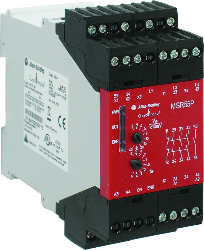
Safety Relay Features          Figure 1 - Overview of Key Features
                                                                                        Removable terminal blocks

                                 Three indicators for status
                                            and diagnostics                             Standstill voltage setting
                                                                                        Standstill time delay setting

                               MSR55P back electro-motive-force (EMF) safety relays monitor the voltage that
                               motors generate after their drive voltage is removed and the motor coasts or
                               brakes to a stop. MSR55P safety relays monitor either single- or three-phase
                               motors. MSR55P safety relays operate with pulse width modulated (PWM)
                               drives, smart motor controllers, and electromechanical contactors.

                               MSR55P safety relays are connected to the motor terminals and measure the
                               induced back EMF as the motor spins to a stop. MSR55P safety relays create a
                               two-channel system by measuring the voltage from L2 to L1 and the voltage
                               from L3 to L1. If the back EMF voltage drops to a certain threshold
                               simultaneously in both channels for a certain duration, standstill is considered
                               achieved, and the outputs are energized.

                               If the voltage measured on terminals L1/L2/L3 of the MSR55P safety relay rises
                               over the adjusted value plus hysteresis in at least one channel (the motor is
                               switched on or the shaft turns mechanically), the forcibly guided output
                               contacts are switched off immediately (contacts 23/24, 33/34 and 43/44 open
                               while contact 11/12 closes). The monitoring relay de-energizes (53/54 opened),
                               the semiconductor output ON goes off and the OUT indicator turns yellow
                               (= Vm over adjusted value).

                               To accommodate many types of motors, you can make two adjustments in
                               accordance with the machine risk assessment:
                                  •     The threshold of the back EMF voltage.
                                  •     A time delay to add additional assurance that the motor has stopped.

                        Rockwell Automation Publication 440R-UM014H-EN-P - March 2022                                          7
Chapter 1   Overview

                              MSR55P safety relays can monitor external safety relays and contactors. By
                              monitoring the normally closed contacts, MSR55P safety relays help prevent
                              re-energization of its outputs if the safety relays or contactors have not
                              de-energized. If feedback monitoring is not required, the monitoring circuit
                              must be jumpered.

                              MSR55P safety relays perform internal tests on startup and during operation.
                              Some faults are reset automatically when the fault is cleared. Other faults are
                              reset manually, by a manually operated switch, or automatically by a jumper.
                              See Status Indicators and Diagnostics on page 25 and
                              Troubleshooting on page 35 for further details.

                              Table 2 lists the six catalog numbers that are available. The key differences are
                              the power supply to terminals A1/A2 and the set point voltage to determine
                              safe standstill speed as the motor spins to a stop.

                              In general, select models that have the lower standstill monitoring voltage
                              when induction motors are monitored. Servo motors, which have permanent
                              magnets, generally create high voltages at slower revolutions, therefore, the
                              higher standstill monitoring voltage is usually the preferred solution. You
                              must evaluate your application and apply the risk assessment process to
                              determine the proper relay for their specific application.
                              Table 2 - Model Selection
                                                            Standstill Monitoring
                                 A1/A2 Supply Voltage                                  Typical Applications    Cat. No.
                                                               Voltage Range
                                        24V DC                  20…400 mV                                     440R-S35011
                                        115V AC                 20…400 mV                Induction motors     440R-S35012
                                        230V AC                 20…400 mV                                     440R-S35013
                                        24V DC                  200 mV…4V                                     440R-S35014
                                        115V AC                 200 mV…4V               Servo (permanent      440R-S35015
                                                                                         magnet) motors
                                        230V AC                 200 mV…4V                                     440R-S35016

8                      Rockwell Automation Publication 440R-UM014H-EN-P - March 2022
Chapter   2

                               Installation

Mounting Dimensions            MSR55P safety relays come standard with removable screw-type terminals.
                               Spring-clamp terminals are offered as an option. Figure 2 shows the mounting
                               dimensions.

                               Figure 2 - Dimensions [mm (in.)]
                                                                            121 (4.8)
                                      45 (1.8)                                          113 (4.4)

                                                                                                       104 (4.1)
                                                                    90                              Screw Terminals
                                                          35       (3.5)
                                                         (1.4)                                         111 (4.4)
                                                                                                     Spring-clamp
                                                                                                       Terminals

DIN Rail Mounting and          MSR55P safety relays mount onto 35 mm (1.4 in.) DIN rails:
Removal                        35x7.5x1 mm(1.4x0.3x0.03 in.) — EN 50022 - 5x7.5.
                                  1. Hold the top at an angle (Figure 3).
                                  2. Slide down until the housing catches the rail.
                                  3. Swing the bottom down and push until the latch clips onto the rail.
                               Figure 3 - DIN Rail Mounting

                                        DIN Rail Latch           DIN Rail

                        Rockwell Automation Publication 440R-UM014H-EN-P - March 2022                                           9
Chapter 2   Installation

                                  Removal

                                  To remove the MSR55P safety relay, use a screwdriver to pry the DIN rail latch
                                  downwards until it is in the unlatched position. Then, swing the module up.

                                  Spacing

                                  MSR55P safety relays can be mounted directly next to other MSR and GSR
                                  safety relays.

                                  Maintain a space of 50.8 mm (2 in.) above, below, and in front of the relay for
                                  adequate ventilation.

Removable Terminals               MSR55P safety relays have removable terminals to ease wiring and
                                  replacement.

                                  Figure 4 - Removable Terminals
                                  M4105_a

                                            1. Insert the tip of a small screwdriver into the slot near the terminal
                                               screws.
                                            2. To unlock the terminal block, rotate the screwdriver.

                                  The terminal block can then be removed from the housing.

10                         Rockwell Automation Publication 440R-UM014H-EN-P - March 2022
Chapter 2   Installation

Enclosure Considerations        Most applications require installation in an industrial enclosure to reduce the
                                effects of electrical interference and environmental exposure. Pollution
                                Degree 2 is an environment where normally only non-conductive pollution
                                occurs except that occasionally temporary conductivity from condensation can
                                be expected. Overvoltage Category II is the load level section of the electrical
                                distribution system. At this level, transient voltages are controlled and do not
                                exceed the impulse voltage capability of the product insulation.

                                This equipment is intended for use in a Pollution Degree 2 industrial
                                environment, in overvoltage Category II applications (as defined in
                                IEC 60664-1), at altitudes up to 2000 m (6562 ft) without derating. This
                                equipment is considered Group 1, Class A industrial equipment according to
                                IEC/CISPR 11. Without appropriate precautions, there can be difficulties with
                                electromagnetic compatibility in residential and other environments due to
                                conducted and radiated disturbances.

                                This equipment is supplied as open-type equipment. The relays must be
                                mounted within an enclosure that is suitably designed for those specific
                                environmental conditions that are present and appropriately designed to help
                                prevent personal injury as a result of accessibility to live parts. The interior of
                                the enclosure must be accessible only by the use of a tool. Subsequent sections
                                of this publication contain additional information regarding specific
                                enclosure-type ratings that are required to comply with certain product safety
                                certifications.

                                For more information, see:
                                   •    Publication 1770-4.1, for additional installation requirements.
                                   •    NEMA Standard 250 and IEC 60529, as applicable, for explanations of the
                                        degrees of protection provided by different types of enclosure.

Help Prevent Excessive          For most applications, normal convective cooling keeps the relay within the
Heat                            specified operating range. Verify that the specified temperature range is
                                maintained. Usually, proper spacing of components within an enclosure is
                                sufficient for heat dissipation.

                                In some applications, other equipment inside or outside the enclosure can
                                produce a substantial amount of heat. In this case, place blower fans inside the
                                enclosure to help with air circulation and to reduce hot spots near the
                                controller.

                                Additional cooling provisions are necessary when high ambient temperatures
                                are encountered. Do not bring in unfiltered outside air. Place the controller in
                                an enclosure to help protect it from a corrosive atmosphere. Harmful
                                contaminants or dirt could damage components or cause improper operation.
                                In extreme cases, you will need air conditioning to help protect against heat
                                buildup within the enclosure.

                         Rockwell Automation Publication 440R-UM014H-EN-P - March 2022                               11
Chapter 2   Installation

Notes:

12                         Rockwell Automation Publication 440R-UM014H-EN-P - March 2022
Chapter     3

                                 Power, Ground, and Wire

Wiring Requirements and
Recommendation                                  ATTENTION: Before you install and wire any device, disconnect power to
                                                the system.

                                                ATTENTION: Calculate the maximum possible current in each power and
                                                common wire. Observe all electrical codes that dictate the maximum
                                                current allowable for each wire size. Current above the maximum rating
                                                causes the wiring to overheat, which can cause damage.
                                    •    Allow for at least 50 mm (2 in.) between I/O wire ducts or terminal strips
                                         and the relay.
                                    •    Route incoming power to the relay by a path separate from the device
                                         wiring. Where paths must cross, their intersection must be
                                         perpendicular.
                                    •    Do not run signal or communications wiring and power wiring in the
                                         same conduit. Route wires with different signal characteristics by
                                         separate paths.
                                    •    Separate wiring by signal type. Bundle wiring with similar electrical
                                         characteristics together.
                                    •    Separate input wiring from output wiring.
                                    •    Label wiring to all devices in the system. Use tape, shrink-tubing, or
                                         other more dependable means to label wire. Use colored insulation as
                                         well to identify wiring by signal characteristics. For example, use blue for
                                         DC wiring and red for AC wiring.

                                 Wire Size and Terminal Torque

                                 See Table 11 on page 41.

                                 Terminal Assignment

                                 The safety relays have eight terminal blocks: four on the top and four on the
                                 bottom. Figure 5 on page 14 shows the front face marking of each of the relays,
                                 including the terminal and status indicator identifications. The difference
                                 between the two models is the standstill monitoring voltage, Vm.

                          Rockwell Automation Publication 440R-UM014H-EN-P - March 2022                                  13
Chapter 3   Power, Ground, and Wire

                                             In Figure 5, the monitoring voltage of the relay on the left is 200 mV…4V; the
                                             relay on the right has a monitoring voltage from 20…400 mV.

                                             Figure 5 - Relay Face and Terminal Identification

                                               53    54              L1         L2         L3     53   54           L1         L2        L3
                                               X1    X2     X3             11   23   33    43     X1   X2    X3           11   23   33   43
                                              PWR
                                                                                MSR55P           PWR
                                                                                                                               MSR55P
                                              OUT     .2 .3 .4    Vm       11 23 33 43 53        OUT    2 3 4     x10mVm 11 23 33 43 53
                                                               .5                                                 5
                                                                .7                                                 7
                                              ERR                1                               ERR                10
                                                      4 3 2   1.5                                               15
                                                                                                       40 30 20
                                                       .2 .3 .5                                          .2 .3 .5
                                                                 .7                                               .7
                                                                  1                                                1
                                                                  1.5      12 24 34 44 54                          1.5    12 24 34 44 54
                                                      6 4 3      2 ts                                   6 4 3 2 ts
                                                                           12   24   34    44                             12   24   34   44
                                              A3     A4     ON       ERR        A1         A2    A3    A4    ON     ERR        A1        A2

                                             Table 3 lists the terminal functions.

                                             Table 3 - Terminal Assignments and Functions
                                                         Terminal                                                    Function
                                                        A1(+)-A2(-)                                                Power supply
                                                         L1/L2/L3                                               Motor connections
                                                            11/12                         Voltage-free redundant monitoring (non-safety) contacts (N.C.)
                                                    23/24, 33/34, 43/44                            Voltage-free redundant safety contacts (N.O.)
                                                           53/54                                 Voltage-free monitoring (auxiliary) contact (N.O.)
                                                           X1/X2                                         Connection for feedback circuit
                                                           X3/X2                                             Reset for fault conditions.
                                                        A3(+) -A4(-)                                 Power supply for semiconductor outputs
                                                             ON                            Semiconductor output indicates that safety outputs are ON.
                                                            ERR                                  Semiconductor output indicates fault condition.

Connect Power Supply                         Power for the MSR55P safety relay depends on the model. The primary power
                                             supply is connected to terminals A1 and A2. An auxiliary (12…30V DC only)
                                             supply voltage can be connected to terminals A3/A4 to provide semiconductor
                                             diagnostics.

                                             Depending on the model, the primary supply can be 24V DC, 115V AC or 230V
                                             AC. When an AC supply is used, both 50 Hz and 60 Hz are acceptable.

                                             When powering with 24V DC in the European Union, the DC supply must have
                                             a Protective Extra-Low Voltage (PELV) rating. When powering with 24V DC in
                                             the United States, the DC supply must have both a PELV rating and an

14                                    Rockwell Automation Publication 440R-UM014H-EN-P - March 2022
Chapter 3            Power, Ground, and Wire

                              NEC Class 2 rating. Many of the Bulletin 1606 power supplies are PELV and
                              Class 2 compliant.

                              Figure 6 shows the power supply connections. Power to A1 is required to
                              operate the MSR55P safety relay. Power to A3 is only necessary if the solid-state
                              auxiliary status signals (ON and ERR) are used.

                              Figure 6 - Power Supply Connections
                              24V DC
                              or L1 115V AC                                                   12...30V DC
                              or L1 230V AC

                                                  A1    11    23   33   43   53        A3   X1 X2      X3

                                                   A2 12      24   34   44   54 ON ERR A4   L1 L2      L3

                              24V Com                                                         0 V DC
                              or L2 (Neutral)

Motor Winding Inputs          The motor windings are connected to terminals L1, L2, and L3. The
                              connections must be made at the motor level with no electrical devices (like
                              transformers and contactors) between the motor and the MSR55P safety relay.

                              Fuses are acceptable, but not required, between the motor and the MSR55P
                              safety relay. Fuses must be 0.05…0.5 A. You must select the appropriate voltage
                              rating. Fuses must be installed in a minimum IP54-rated enclosure. Catalog
                              number 140F-D3F-C30 is a 3-phase fuse holder for UL Class CC or midget fuses
                              and IEC 10x38 mm fuses. See publication 140F-TD001.

                              Check local regulations for the protection requirements when the sensing
                              wires are connected outside the control panel, directly to the motor.

                              Figure 7 shows wiring for a single-phase and DC motor. Figure 8 on page 16
                              shows wiring for a 3-phase motor.

                                    IMPORTANT                 The three connections create two safety monitoring channels. L1 is the
                                                              common to the two channels, which are L2 and L3.
                              Figure 7 - Single-phase and DC Motor Connections
                                  A3     X1 X2                          L1 N                 A3   X1 X2                                        L1 N
                                                  X3                                                        X3
                                                                                  K1                                                                  K1

                                                                                  K2                                                                  K2
                                        MSR55P                                                    MSR55P
                                  A4     L1 L2    L3                                         A4   L1 L2     L3
                                                         F1                                                            Protected   Cable
                                                                                                                         Protected Cable
                                                                                                                 F1
                                                         F2
                                          Sensor  Wiring
                                           Sensor Wiring                                                         F2
                                           Internal to Cabinet
                                          Internal     Cabinet                                      Sensor
                                                                                                     Sensor Wiring
                                                                                                            Wiring
                                                                         M                           External to
                                                                                                    External  to Cabinet
                                                                                                                 Cabinet                        M

                       Rockwell Automation Publication 440R-UM014H-EN-P - March 2022                                                                            15
Chapter 3   Power, Ground, and Wire

                                             Figure 8 - 3-phase Motor Connections
                                                 A3     X1 X2                           L1 L2    L3            A3    X1 X2                                 L1 L2   L3
                                                                 X3                                                             X3
                                                                                                     K1                                                             K1

                                                                                                     K2                                                             K2
                                                      MSR55P                                                         MSR55P
                                                 A4     L1 L2     L3                                           A4    L1 L2      L3     Protected   Cable
                                                                                                                                         Protected Cable
                                                                       F1
                                                                       F2                                                       F1
                                                                       F3                                                       F2
                                                       Sensor  Wiring                                                           F3
                                                        Sensor Wiring                                                Sensor Wiring
                                                                                                                    Sensor  Wiring
                                                        Internal to
                                                       Internal  to Cabinet
                                                                    Cabinet
                                                                                           M                         External totoCabinet
                                                                                                                    External       Cabinet                    M

Safety Outputs                               The safety outputs consist of two redundant positive-guided relays that are
                                             connected in series. Terminals 11/12 are normally closed monitoring
                                             (non-safety). Terminals 23/24, 33/34, and 43/44 are normally open. The outputs
                                             can drive loads that are either AC or DC powered. Figure 9 shows typical
                                             connections of the safety outputs to safety contactors.

                                             Figure 9 - Safety Outputs
                                             24V DC
                                             or L1 115V AC
                                             or L1 230V AC

                                                                  A1   11     23   33    43     53        A3   X1 X2      X3

                                                                  A2 12       24   34    44     54 ON ERR A4   L1 L2       L3

                                                                              K1   K2    K3
                                             24V Com
                                             or L2 (Neutral)

                                             Derating Curve
                                             The currents through the safety outputs are subject to derating. The derating
                                             depends on the current through each of the outputs and the ambient
                                             temperature. Figure 10 shows a graphical representation of the current limit
                                             over the ambient temperature range.

                                             Calculate the total quadratic current, which is the sum of the squares of the
                                             currents through each of the safety outputs.

                                             I12+ I22 + I32 = ΣI2 (A2)

                                              Variable          Description
                                              I1, I2, I3        The currents in contact paths 23/24, 33/34 and 43/44

                                             Then, use the graph in Figure 10 on page 17 to find the highest ambient
                                             temperature that is allowed.

16                                    Rockwell Automation Publication 440R-UM014H-EN-P - March 2022
Chapter 3   Power, Ground, and Wire

       Figure 10 - Safety Output Derating Curve

                                           80

       Total Quadratic Current Σ I2 (A2)
                                           70
                                           60
                                           50
                                           40
                                           30
                                           20
                                           10

                                                 0     10        20      30       40   50   60
                                                            Ambient Temperature (°C)

                             •                  Example 1: A 5-amp load through each of the three output circuits.

                                                52 + 52 + 52 = 75 A

                                                From the derating curve, the maximum permitted ambient temperature
                                                is 40 °C (104 °F).
                             •                  Example 2: A 2-amp load through each of the three output circuits.

                                                22 + 22 + 22 = 12 A

                                                From the derating curve, the maximum permitted ambient temperature
                                                is 60 °C (140 °F).

       Surge Suppressors

       Because of the potentially high current surges that occur when switching
       inductive load devices, such as motor starters and solenoids, the use of surge
       suppression is required. The addition of a suppression device prolongs the life
       of the relay outputs and reduces the effects of voltage transients and electrical
       noise from radiating into adjacent systems.

       Since this system is safety-related, the surge suppression device must be
       connected across the load device. The surge suppression device must not be
       connected across the MSR55P relay contacts.

       Figure 11 shows examples of output contactors with a suppression device. We
       recommend that you locate the suppression device as close as possible to the
       load device.

       For outputs that use 24V DC, we recommend 1N4001 (50V reverse voltage) to
       1N4007 (1000V reverse voltage) diodes for surge suppression for the OSSD
       safety outputs, as shown in Figure 11. The diode must be connected as close as
       possible to the load coil.

       For outputs that use 120V AC or 240V AC, we recommend metal oxide
       varistors.

Rockwell Automation Publication 440R-UM014H-EN-P - March 2022                                                                     17
Chapter 3   Power, Ground, and Wire

                                             Some devices, like the Bulletin 100S-CxxEJ and 100S-CxxQJ safety contactors
                                             have built-in suppression, therefore additional suppression devices are not
                                             needed.

                                             Figure 11 - Surge Suppression Components
                                             Metal Oxide Varistors                                  Diodes
                                                for VAC supply                                  for VDC supply

                                                  K1                K2                         K1              K2

                                                     V common                                       V common

Auxiliary Outputs                            Auxiliary contacts are intended to convey status information to the machine
                                             control system (programmable logic controller [PLC]) or to an indicator light.
                                             They must not be used in the safety-related circuits. Figure 12 shows an
                                             example of the auxiliary circuits.

                                             MSR55P safety relays have one auxiliary voltage-free contact and two
                                             solid-state contacts.

                                             The voltage-free contact is terminals 53/54. This contact can accommodate a
                                             DC or AC voltage up to 230V. Terminal 53/54 closes when the safety outputs are
                                             energized.

                                             MSR55P safety relays have two semiconductor auxiliary outputs. The ON
                                             output turns on when the outputs are energized. The ERR output turns on
                                             when an error is detected by the MSR55P safety relay. The semiconductor
                                             outputs require a separate 24V DC connection and must have a common
                                             reference to the PLC.

                                             Figure 12 - Example Auxiliary Circuits
                                              24V DC
                                              or L1 115V AC                                                 12...30V DC
                                              or L1 230V AC

                                                               A1   11   23     33   43   53          A3   X1 X2    X3

                                                               A2 12     24     34   44   54 ON ERR A4     L1 L2     L3

                                                                    PLC                                              PLC
                                                               DC or AC Input                                      DC Input

                                             24V Com
                                             or L2 (Neutral)                                                        OV DC

18                                    Rockwell Automation Publication 440R-UM014H-EN-P - March 2022
Chapter 3      Power, Ground, and Wire

Monitoring Input                Monitoring of external devices, like safety control relays and safety contactors,
                                can be accomplished by adding their normally closed contacts between X1 and
                                X2. The safety outputs of the MSR55P safety relay are enabled only if the
                                feedback loop X1/X2 is closed while standstill is detected, that is the external
                                contactors/components are in initial state (N.C. contacts are closed).

                                The feedback circuit X1/X2 must be closed as long as the safety outputs are
                                disabled. If not, the ERR indicator shows fault code 4.

                                In some applications, where monitoring cannot be done, install a jumper
                                between X1 and X2. The jumper is shown in the No Monitoring diagram in
                                Figure 13.

                                If additional devices must be controlled, safety control relays or contactors can
                                be connected to the safety outputs of the MSR55P safety relay. The MSR55P
                                safety relay can monitor the status of these devices by connecting their
                                voltage-free contacts in series, as shown in the Contactor Monitoring diagram
                                in Figure 13.

                                The MSR55P safety relay is shipped from the factory with a jumper from X1 to
                                X2.

                                                         ATTENTION: Terminals X1-X2-X3 have electrical connections to measuring
                                                         inputs L1-L2-L3. Voltage-free contacts that are rated for L1-L2-L3 voltage
                                                         must be used for these connections.
                                Figure 13 - Examples of Feedback Monitoring Circuits

                                                                                                                                     K1

                    24V DC                                                                                                           K2

                                                                                                                                     K3

                    A1    11   23    33     43    53             A3   X1 X2   X3          A1    11   23   33   43   53          A3        X1 X2   X3

                    A2 12      24    34     44    54 ON ERR A4        L1 L2   L3          A2 12      24   34   44   54 ON ERR A4          L1 L2   L3

                                          Guard Locking Device
                                           (Power to Unlock)
                                          Unlock Command                                             K1    K2 K3
                                          24V Com

                   24V Com
                                    No Monitoring                                              Contactor Monitoring

                         Rockwell Automation Publication 440R-UM014H-EN-P - March 2022                                                             19
Chapter 3   Power, Ground, and Wire

Fault Reset Input                            The X2/X3 connection can reset some external faults. The reset can occur
                                             automatically or manually. The MSR55P safety relay is shipped from the
                                             factory with a jumper from X2 and X3 for automatic reset. A voltage-free
                                             contact can be used to reset a fault condition manually.

                                                                     ATTENTION: Terminals X1-X2-X3 have electrical connections to measuring
                                                                     inputs L1-L2-L3. Voltage-free contacts that are rated for L1-L2-L3 voltage
                                                                     must be used for these connections.

                                             If control of terminal X3 must be by a push button or by a PLC via an
                                             interposing relay, the push button or relay must have the necessary insulation
                                             between the motor voltage and PLC potential. Figure 14 shows two typical
                                             connections to the fault reset input.

                                             Figure 14 - Fault Reset Circuit Examples

                                               A1   11   23   33     43   53           A3   X1 X2   X3   A1   11   23   33   43   53              A3   X1 X2   X3

                                               A2 12     24   34     44   54 ON ERR A4      L1 L2   L3   A2 12     24   34   44   54 ON ERR A4         L1 L2   L3
                                                                   Automatic Fault Reset                                     Manual Fault Reset

20                                    Rockwell Automation Publication 440R-UM014H-EN-P - March 2022
Chapter        4

                                 Configuration

                                 The configuration of MSR55P safety relays is accomplished by adjusting the
                                 two switches on the front face. Each switch control knob rotates two
                                 potentiometers. The recommended practice is to set the switches to the
                                 minimum setting initially, and then adjust them as necessary to reduce
                                 nuisance tripping while maintaining a safe application.

Vm - Monitoring Voltage          The trip voltage of the back EMF is adjusted by the ten position Vm
                                 potentiometer. When the back EMF drops below the voltage level, the MSR55P
                                 safety relay begins the delay timer. When the voltage exceeds that voltage
                                 setting, the outputs are de-energized. Table 4 shows the settings of each of the
                                 catalog numbers.

                                 Table 4 - Vm - Monitoring Voltage Settings
                                                 440R-S35014, 440R-S35015, 440R-S35016    440R-S35011, 440R-S35012, 440R-S35013
                                   Position                     [Volts]                                  [x10mV]
                                       1                          0.2                                        2
                                       2                          0.3                                        3
                                       3                          0.4                                        4
                                       4                          0.5                                        5
                                       5                          0.7                                        7
                                       6                          1.0                                       10
                                       7                          1.5                                       15
                                       8                          2.0                                       20
                                       9                          3.0                                       30
                                      10                          4.0                                       40

                          Rockwell Automation Publication 440R-UM014H-EN-P - March 2022                                           21
Chapter 4   Configuration

ts - Time Delay                    When the back EMF of the motor drops below the Vm voltage setting, the
                                   standstill delay timer starts. The delay time is set by the 10 position ts
                                   potentiometer. During the timing cycle, the OUT indicator flashes. Table 5
                                   shows the delay time for each setting. After the delay expires, the outputs are
                                   energized.

                                   Table 5 - Delay Time Settings
                                           Position        Delay Time [seconds]
                                               1                    0.2
                                               2                    0.3
                                               3                    0.5
                                               4                    0.7
                                               5                    1.0
                                               6                    1.5
                                               7                    2.0
                                               8                    3.0
                                               9                    4.0
                                              10                    6.0

22                          Rockwell Automation Publication 440R-UM014H-EN-P - March 2022
Chapter          5

                             Timing Diagram

Timing Diagram Procedure     A typical timing diagram of MSR55P safety relays is shown in
                             Figure 15 on page 24.
                                1. Upon power-up, the MSR55P safety relay performs internal safety
                                    checks.
                                2. With the motor at standstill, the outputs are energized.
                                3. When the motor is turned ON, the outputs are de-energized.
                                4. A motor stop command is issued, and the motor spins down.
                                5. The back EMF reaches the level of the Vm setting, the standstill delay
                                    timer starts. The position of the ts potentiometer determines the
                                    duration of the delay.
                                6. When the timing cycle completes, standstill is considered achieved and
                                    the outputs are energized.
                                7. If one of the monitoring voltage signal lines break, the outputs are
                                    de-energized and the semiconductor ERR output turns ON after 2.5
                                    seconds.
                                8. If the line is reconnected, no changes are noticed if the manual fault reset
                                    is used.
                                9. When the fault reset is closed, the outputs are energized.
                                10. The motor is turned back on, and the safety outputs are de-energized.
                                11. When voltage-free contacts control the motor, the MSR55P safety relay
                                    can detect line breakage on L2 and L3. After a 2.5 second delay, the
                                    semiconductor ERR signal turns ON. The ERR signal must be used to
                                    initiate a stop command to the motor. The outputs remain de-energized.

                                 IMPORTANT         The MSR55P safety relay does not detect line breakage with the motor
                                                   running and connected to an electronic drive.
                                12. The line break is reinstated.
                                13. Upon closure of the reset signal, the outputs are energized.

                      Rockwell Automation Publication 440R-UM014H-EN-P - March 2022                                       23
Chapter 5   Timing Diagram

                                    Figure 15 - Typical Timing Diagram

                                                                                                                     Back EMF reaches trip point
                                                                        Safety Outputs Energized

                                                                                                                                                                                                           Line breakage (See text)
                                                                                                                     Standstill detected
                                                    Supply voltage on

                                                                                                                                                                                                           Motor runs down
                                                                                                                                                          Line breakage

                                                                                                                                                                              Reset X3 - X2

                                                                                                                                                                                                                                         Reset X3 - X2
                                                                                                                                                                                               Motor on
                                                                                                   Motor on

                                                                                                              Stop
                                                      1                   2                         3          4       5 6                           7                    8    9               10 11                                  12 13
                                            VS

                                       A1/A2                                                                                                                                                                                                                  t

                                    motor speed /
                                    voltage
                                     L1/L2/L3                                                                                                                                                                                                            Voltage level (Vm)

                                    line breakage
                                    L1/L2/L3

                                       23-24
                                       33-34
                                       43-44
                                       53-54
                                       ON

                                      11-12

                                      ERR                                                                                                 tE                                                  tE

                                                                                                                                                   Standstill delay time ts
                                                                                                                                                                                                   tE =2...2.5s
                                                                                                      Start up delay time

24                           Rockwell Automation Publication 440R-UM014H-EN-P - March 2022
Chapter        6

       Status Indicators and Diagnostics

       Three indicators on the front provide the operating status of the MSR55P
       safety relay. Table 6 describes the state of each indicator.

       Table 6 - Status Indicators
        Indicator        State                              Description
                         Off                                No power to A1
        VS               Green                              Normal operation
                         Red                                Internal Fault
                         Green                              Safety outputs are energized
                         Flashing green                     In a timing cycle
        OUT              Flashing orange                    Intermittent crossing of the Vm trip point
                         Orange                             Safety outputs are de-energized
                         Off                                Code 1 or code 5 error is present
                         Off                                No faults exist; normal operation
        ERR
                         Flashing red                       Fault is present. See ERR Flashing Codes on page 26.

       MSR55P safety relays include a number of facilities to detect faults that could
       influence the safety function of the module. Checks are conducted on power-
       up of the unit and in cycles during normal operation. If a fault occurs, the
       output relays switch off. The fault state is indicated with the ERR indicator, the
       VS indicator, and the semiconductor output ERR.

       With safety relevant failures, your MSR55P safety relay differentiates between
       external failures (broken wire/offset, simultaneity failure, or feedback circuit
       failure) and internal failures.

       Broken wire/offset failures and feedback circuit failures can be restored by
       using manual reset. They can also be reset automatically after removing the
       fault by placing a jumper from terminal X2 to X3.

       The number of times the ERR status indicator blinks communicates
       diagnostics. When multiple faults exist simultaneously, the ERR indicator
       shows the highest priority. After the highest priority fault is corrected, the ERR
       shows the next highest priority fault. Figure 16 on page 26 shows the codes in
       order of priority.

Rockwell Automation Publication 440R-UM014H-EN-P - March 2022                                                      25
Chapter 6   Status Indicators and Diagnostics

ERR Flashing Codes                              Figure 16 - ERR Flashing Codes
                                                             1) Undervoltage at VS

                                                    2) Wire-break/offset on L1 or L2

                                                          3) Wire-break/offset on L3

                                                4) Failure in feedback circuit X1-X2

                                                   5) Simultaneity failure signal L2/L3

                                                           6) Potentiometer error Vm

                                                             7) Potentiometer error ts
                                                                                          0s                                    2s       4s
                                                                                                                                     t
                                                                  Flashing codes of the ERR indicator in sequence of priority

Line Breakage                                   Line breakage can be detected at standstill or with the motor spinning.

                                                With Motor at Standstill

                                                With the motor at standstill, the outputs of the MSR55P safety relay are
                                                energized. A break in the wires at L1, L2, and L3 is detected. The ERR indicator
                                                flashes and the ERR semiconductor output turns ON.
                                                   •      L3 - The ERR indicator flashes three times.
                                                   •      L2 - The ERR indicator flashes two times.
                                                   •      L1 - The ERR indicator flashes two times.

                                                With Motor Spinning
                                                   •      Electronic Drive

                                                          In the case where the motor is spinning under the command of an
                                                          electronic drive, the outputs are de-energized. Line breakage is not
                                                          detected by the MSR55P safety relay. This state is still considered a safe
                                                          situation because the outputs of the MSR55P safety relay are
                                                          de-energized. When the drive turns off, and the motor spins to a
                                                          standstill; the line breakage is detected and the following occurs:
                                                          - The outputs of the MSR55P safety relay remain de-energized.
                                                          - The ERR output turns ON.
                                                          - The ERR status indicator flashes the code that is associated with the
                                                            breakage.

26                                       Rockwell Automation Publication 440R-UM014H-EN-P - March 2022
Chapter 6   Status Indicators and Diagnostics

                                  •    Voltage-free Contactor

                                       The MSR55P safety relay detects line breakage on L1, L2, and L3. The ERR
                                       semiconductor output turns ON and the ERR indicator flashes the
                                       appropriate number of times. The machine-controlled system continues
                                       to control the motor. This state is considered a safe situation because the
                                       outputs of the MSR55P safety relay are de-energized. The machine
                                       control system can respond to the ERR output and turn off the motor.
                                       When the contactor turns off, and the motor spins to a standstill; the line
                                       breakage is detected and the following occurs:
                                       - The outputs of the MSR55P safety relay remain de-energized.
                                       - The ERR output turns ON.
                                       - The ERR status indicator flashes the code that is associated with the
                                         breakage.

Simultaneity of Measuring      As an additional safety feature, the two input signals (L2 and L3) are compared
Signals                        continuously. This feature allows the MSR55P safety relay to detect internal
                               failures in one measuring signal.

                               If the signals are different for at least 2.5 s (one channel >Vm, the other
Chapter 6   Status Indicators and Diagnostics

Internal Device Failure                         Internal failures are always stored independent of the reset input X3. Internal
                                                failures cause the output relays to switch off immediately, the semiconductor
                                                output ERR to switch on, and the VS indicator to change from green to red.

                                                Examples for internal failures include:
                                                   •    Failure on safety relays (for example, welded output contacts).
                                                   •    Internal failures on measuring channels and measuring circuits.
                                                   •    Internal failures on control circuits for the safety relays.

                                                Cycle power to terminal A1 to clear the fault.

28                                       Rockwell Automation Publication 440R-UM014H-EN-P - March 2022
Chapter     7

                              Application and Wiring Examples

                              This chapter provides typical examples of applications and wiring diagrams to
                              help you understand how the MSR55P safety relay can be applied. You must
                              perform a risk assessment and make appropriate adjustments to these
                              examples to provide the safety performance that is required for your
                              application.

                              These applications show a focus on functional safety. You must also consider
                              safety features including fuses, circuit breakers, and overload protection.

Guard Locking and E-stop      Figure 17 on page 30 shows a typical application where the MSR55P safety relay
with Electronic Drive         monitors the speed of a motor. In this application, a PowerFlex® 525 drive
                              controls the speed and direction of the motor. The MSR55P safety relay allows
                              access to the hazard after the motor has achieved its standstill settings. The
                              GSR DIS safety relay monitors the MSR55P through contacts 23/24, the guard
                              locking switch, and the E-stop push button. The DIS safety relay enables the
                              drive to restart after the gate is closed and locked and the E-stop is released.

                              The 440G-LZ switch can be replaced with the TLS-ZR switch if a higher gate-
                              holding force is needed. The 440G-MZ switch can also be used in place of the
                              440G-LZ switch, but the wiring is different. See Figure 20 on page 34 for a 5-pin
                              wiring example.

                              Shielded cable must be used for the motor-monitoring wires L1, L2, and L3. The
                              shield must be grounded.

                       Rockwell Automation Publication 440R-UM014H-EN-P - March 2022                         29
Chapter 7       Application and Wiring Examples

Table 7 - Guard Locking and E-stop with Electronic Drive
Application            Description
                       Close and lock the safety gate, release the E-stop, and press the Reset button. The DIS safety outputs enable the STO inputs (S1 and S2) and the
Safety Enable          Start/Stop inputs of the PowerFlex 525 drive.
Production Start       With the safety system enabled, press the Start button to energize the PowerFlex 525 drive-controlled motor.
Production Stop        A normal production stop is accomplished by pressing the Stop push button.
Safety Stop            A safety stop is initiated by pressing the E-stop push button.
                       The MSR55P can detect standstill after a production stop or a safety stop is initiated. When the motor spins down to a level below the point where
                       it is generating less than 700 mV, the MSR55P safety relay starts its standstill time-delay timer. After 3 seconds, the MSR55P safety relay energizes
Standstill Detection   its outputs, which allows the gate to be unlocked. The unlock circuit must pass through one of the safety outputs of the MSR55P (for example
                       terminals 23/24).
                       Use the Lock/Unlock selector switch to unlock the gate and gain access to the hazardous area. The selector switch holds the 440G guard locking
Unlock the Safety Gate switch in the unlocked state. The 440G switch releases the lock and turns its safety outputs off. The DIS safety relay is set to AND logic, therefore,
                       the DIS safety relay cannot be reset until both the gate is closed and lock, AND the E-stop is released.
                       Close  the gate. Use the Lock/Unlock selector switch to lock the gate. With the E-stop released, press the Reset button to enable the safety system
Lock the Safety Gate and allow    production to restart.
                       This application has two safety functions:
                       1. Release of the guard locking only when the motor is stationary. This safety function meets Cat 4, PLe, SIL 3 due to the rating of the MSR55P.
                       2. STO of the drive when the gate is unlocked or the E-stop is pressed. This safety function is limited to Cat 3, PLd, SIL 2 due to the rating of the
Safety Rating              PF525.
                       For guidance on safety system analysis with frequency drives,
                       see https://www.dguv.de/medien/ifa/en/pub/rep/pdf/reports2013/ifar0713e/rep0713engl.pdf IFA Report 7/2013e,
                       Safe drive controls with frequency converters.

                                                             Figure 17 - Example Schematic
            +24V DC            440G-LZ
                               Guard Locking Switch                                                                                                                                         L1 L2 L3
                               440G-LZS21SPRA
                                                                     Reset R                                                                                                    PowerFlex   R S T
                                                                     800FM-                                                                                                       525
                                             E-stop                  F611MX10
                                   440G-LZ
                                             800FM-MT64MX02S                                                                                                               1 Stop
                                    Status
                                     Diag
                                                                        Status
                                                                        To PLC                                                                                             2 Start

                                               S11 S21 S12 S22 A1 L12 Y32 S34         A1   11   23   33      43   53                 A3        X1 X2            X3         4 Gnd
                                                           01                                                          MSR55P                         2 3 45
                                                                                                                                                 Vm            7
                                                   LOGIC     2                                                         440R-S35011             x10mV           10
                                                             3                                                                                       40 30 2015
                                                     8
                           889D-F5NC-5                 76 5 4                                                                                       .2 .3 .5.7
                                               DIS                                                                                                 ts         1            Gate control
                                               440R-D22S2                                                                                            64 32
                                                                                                                                                              1.5
                                                                                                                                                                           power supply
                                               S32 S42 L11 A2 34 44 14 24             A2 12     24   34      44   54 ON ERR A4                 L1 L2                L3
                                Brown Gray                                                                                                                                  Gate control
                                   Red                                                                                                                                         circuit
                                Yellow Pink
                                  Blue                                                                                                                                     S1
                                       Green                                                                                                                               S2
                                 White                                                                                                    F1        F2 F3                                   U V W
                                          Lock/Unlock
                                          800FM-
                                          SM22MX10                                               ON Status
                                                                                                                                                                         Shielded Cable
                                    Gate                                                               ON Status
                                    Unlocked
                                    800FM-P4MN3R                                                             Error Status
                                                                                                                                                                                              M
                                                                                                                                                                                              3~
              24V DC Com

30                                                    Rockwell Automation Publication 440R-UM014H-EN-P - March 2022
Chapter 7           Application and Wiring Examples

E-stop with Contactors                                 Figure 18 shows a typical application where the MSR55P safety relay monitors
                                                       the speed of a motor that contactors turn on and off. When the MSR55P safety
                                                       relay detects that the motor has achieved its standstill settings, the MSR55P
                                                       safety relay energizes its outputs. You must perform a risk assessment to
                                                       determine the proper settings of Vm and ts.

                                                       An E-stop initiates a safety stop. A PLC turns the motor on and off, provided
                                                       the safety system is enabled.

                                                       The SI safety relay monitors the contactors K1 and K2, the MSR55P safety relay
                                                       through its contacts 23/24, and the E-stop button is released. The PLC must
                                                       monitor the status of the SI safety relay (terminal Y32). The PLC must turn OFF
                                                       its outputs when the E-stop is pressed.
Table 8 - E-stop with Contactors
Application             Description
Safety Enable           Release the E-stop and press the Reset button.
Production Start/Stop   With the safety system enabled, the PLC can start and stop the motor.
                        Press the E-stop to stop the motor; the motor coasts to a stop. When the motor spins down to a speed below the Vm setting of 70 mV, the MSR55P
Safety Stop
                        safety relay begins its timing sequence. After 3 seconds, the MSR55P safety relay energizes its outputs.
                        The safety system has two functions (E-stop and speed monitoring). Both functions can be used in applications up to Category 4, PLe per ISO13849-1
                        and SIL CL 3 per IEC 60261. The speed monitoring rating of the system depends on how the outputs of the MSR55P safety relay are used.
                        This application has two safety functions:
Safety Rating           1. Enable safety devices only when the motor is stationary. This safety function meets Cat 4, PLe, SIL 3 due to the rating of the MSR55P.
                        2. Initiate a coast-to-stop by pressing the E-stop button. This safety function is limited to Cat 4, PLe, SIL 3 due to the rating of the SI relay, the
                           redundancy, of the E-stop contacts, and the redundancy and monitoring of the contactors.

                                                       Figure 18 - E-stop with Motor Controlled by Contactors
                                        +24V DC
                                                                      Start    Stop
                                          E-stop
                                          800FM-MT64MX02S
                                                                     Inputs
                                                                      PLC             Reset R
                                                                     Outputs          800FM-
                                                                                      F611MX10                                                                                    L1 L2   L3

                                            S11 S21 S22 S12 A1 13 23 S34                         A1   11   23     33     43   53                 A3    X1 X2              X3
                                                                                                                                   MSR55P                      2 3 45
                                               RESET      0                                                                                               Vm            7
                                                                                                                                   440R-S35011          x10mV
                                                                                                                                                              40 30 2015
                                                                                                                                                                        10

                                                  AM                                                                                                            .3 .5
                                                                                                                                                                                           K1
                                                                                                                                                             .2      .7
                                            SI           MM                                                                                                 ts         1
                                                                                                                                                                       1.5
                                            440R-S12R2                                                                                                        64 32
                                                                                                                                                                                           K2
                                                     L11    A2 14 24 Y32                         A2 12     24     34    44    54 ON ERR A4             L1 L2                 L3

                                                                                                                                                      F1 F2          F3
                                                                                                           Safety Devices

                                                                   K1 K2                                        ON Status
                                                                       100S Contactors
                                                                                                                       ON Status
                                                                                                                                                                                     M
                                                                                                                          Error Status                                               3~
                                          24V DC Com

                                               Rockwell Automation Publication 440R-UM014H-EN-P - March 2022                                                                               31
Chapter 7       Application and Wiring Examples

Wye-Delta Connections                                   Figure 19 shows a typical wye-delta application where the MSR55P safety relay
                                                        monitors the speed of a motor that contactors turn on and off. When the
                                                        MSR55P safety relay detects that the motor has achieved its standstill settings,
                                                        the MSR55P safety relay energizes its outputs. You must perform a risk
                                                        assessment to determine the proper settings of Vm and ts.

Table 9 - Wye Delta Connections
Application             Description
Main Start              When the main switch is closed, the wye contactor (K2) energizes and allows a start.
                        Press Start to pull in K1. The K1 contacts hold in the start circuit, starts the rotation of the motor and 700-FEY2QU23 timer relay begins timing.
Production Start        After the time expires, the 700-FEY2QU237 relay drops out the K2 wye contactor and pulls in the K3 delta contactor. The motor is now running at
                        full speed and torque.
                        Press the Stop button. The K1 contactor drops out, the 700-FEY2QU237 opens its outputs, and the motor coasts to a stop. When the motor spins
Production Stop         down to a speed below the Vm setting of 70 mV, the MSR55P safety relay begins its timing sequence. After 3 seconds, the MSR55P safety relay
                        energizes its outputs.
Safety Stop             When the MSR55P safety relay energizes its outputs, K4 and K5 are used to execute the necessary safety stops.
                        The speed monitoring function that is performed by the MSR55P safety relay meets the requirement of Category 4, PLe per ISO13849-1 and SIL CL
Safety Rating           3 per IEC 60261. The rating of the safety functions initiated by K4 and K5 depends on additional circuitry that is not shown.

                                                        Figure 19 - Wye-delta Connections
                        240V AC
                        L1
                        L2
                        L3

                             Main switch

                                                                                                                                                                        K1
                                             Stop

                                  K1         Start     K1
                                                                                                                                         F1       F2        F3                           K3
                                                                                                                                                                              U1 V1 W1
                                                        A1            17                A1   11   23   33   43   53                 A3        L1 L2                L3
                                                                                                                                                     2 3 45
                                                                                                                                                                                M
                                                                                                                      MSR55P                    Vm            7                3~
                                  K1        K2                                                                        440R-S35011             x10mV
                                                                                                                                                    40 30 2015
                                                                                                                                                              10

                                                                                                                                                   .2 .3 .5.7
                                                                                                                                                                              W2 U2 V2
                                                         700-                                                                                     ts         1
                                                                                                                                                             1.5
                                                         FEY2QU23                                                                                   64 32

                                                        A2        18       28           A2 12     24   34   44   54 ON ERR A4                 X1 X2            X3

                                                                                                                                         K4
                                       K1                        K3             K2
                                                                                                                                                                         K2
                                                                                                  K4   K5                                K5
                                                                      K2   K3
                         N

                                                             IMPORTANT               • K2 and K3 must be mechanically interlocked.
                                                                                     • With 3-phase connection of the MSR55P safety relay, the wye
                                                                                       contactor (K2) must be closed after the motor is switched off to
                                                                                       detect standstill. If not, the failure signal “broken wire” blocks the
                                                                                       output contacts in the off position.

32                                               Rockwell Automation Publication 440R-UM014H-EN-P - March 2022
Chapter 7        Application and Wiring Examples

Smart Motor Controller                                Figure 20 on page 34 shows an example application where the MSR55P safety
(SMC) Soft Starter                                    relay monitors the speed of a motor that is controlled by a Smart Motor
                                                      Controller. In this application, an SMC™ soft starter controls the start-up
                                                      acceleration and turn-off deceleration of the motor. The MSR55P safety relay
                                                      allows access to the hazard after the motor has achieved its standstill settings.
                                                      The DIS safety relay monitors the MSR55P through contacts 23/24, the guard
                                                      locking switch, and the E-stop push button. The DIS safety relay enables the
                                                      drive to restart after the gate is closed and locked and the E-stop is released.
Table 10 - SMC Connections
Application              Description
                         Close and lock the safety gate, release the E-stop, and press the Reset button. The DIS safety relay does the following:
                         1. Energizes K1, which applies 230VAC to the SMC soft starter.
Safety Enable
                         2. Applies control power to the SMC soft starter at terminal A1.
                         3. Applies 24V to the Start/Stop circuit.
                         With the safety system enabled, press the Start button to start the motor. The SMC soft starter executes its configured acceleration. The
Production Start         MSR55P safety relay monitors the motor speed. When the speed increases higher than the configured threshold voltage, the MSR55P safety
                         relay helps prevent the unlocking of the gate.
                         A normal production stop is accomplished by pressing the Stop button. The SMC soft starter decelerates the motor according to its
Production Stop          configuration. The MSR55P safety relay monitors the motor speed. When the speed drops below the configured threshold voltage for the
                         configured delay time, the MSR55P safety relay enables the gate to be unlocked.
                         A safety stop is initiated by pressing the E-stop. A safety stop is also initiated by unlocking the gate. In either case, the DIS safety relay turns off
Safety Stop              its safety outputs and helps prevent the motor from starting.
                         When the motor spins down to a level below the point where it is generating less than 20 mV, the MSR55P safety relay starts its standstill time-
Standstill Detection     delay timer. After 3 seconds, the MSR55P safety relay energizes its outputs, which allows the gate to be unlocked. The unlock circuit must pass
                         through one of the safety outputs of the MSR55P safety relay (for example, terminals 23/24).
                         Use the Lock/Unlock selector switch to unlock the gate and gain access to the hazardous area. The selector switch holds the 440G guard
Unlock the Safety Gate   locking switch in the unlocked state. The 440G switch releases the lock and turns its safety outputs off. The DIS safety relay is set to AND logic,
                         therefore, the DIS safety relay cannot be reset until both the gate is closed and lock, AND the E-stop is released.
                         Close the gate. Use the Lock/Unlock selector switch to lock the gate. With the E-stop released, press the Reset button to enable the safety
Lock the Safety Gate     system and allow production to restart.
                         This application has two safety functions:
                         1. Release of the guard locking only when the motor is stationary. This safety function meets Cat 4, PLe, SIL 3 due to the rating of the MSR55P
                            safety relay.
Safety Rating            2. The safety function that the gate or E-stop initiates meets Cat 4, PL3, SIL 3 due to the rating of the DIS safety relays, 100S contactor, and the
                            monitoring of both the contactor and the SMC soft starter.
                         For guidance on safety system analysis with frequency drives,
                         see www.dguv.de/medien/ifa/en/pub/rep/pdf/reports2013/ifar0713e/rep0713engl.pdf IFA Report 7/2013e,
                         Safe drive controls with frequency converters.

                                              Rockwell Automation Publication 440R-UM014H-EN-P - March 2022                                                                    33
Chapter 7          Application and Wiring Examples

                                                               Figure 20 - SMC Soft Starter Schematic, Cat. 4, PLe, SIL 3
     +24V DC
                      440G-MZS20SNRJ                                                                                                                                                                      230V AC
                      Power-To-Release                                                                                                                                                               L1    L2     L3
                      Guard Locking Switch                                                                                                                             Stop
                                                            Reset
                                     E-stop                 800FM-       R
                                     800FM-MT64MX02S        F611MX10                                                                                                                                                   K1
                                                                                                                                                                       Start

                                        S11 S21 S12 S22 A1 L12 Y32 S34       A1   11   23   33      43   53                 A3        X1 X2                X3          11      IN1 IN2 13 97    A1   1      3     5
                                                    01                                                        MSR55P                         2 3 45             150-
                                                                                                                                        Vm           7
                                            LOGIC     2                                                       440R-S35011             x10mV          10         CA11
                                              8       3                                                                                     40 30 2015                             Aux#1     OVLD
                                                76 54                                                                                         .3
                                                                                                                                           .2 .5.7                                           Fault
                   889D-F5NC-5          DIS                                                                                               ts         1
                                                                                                                                                     1.5
                                                                                                                                                                               SMC-3
                                        440R-D22S2                                                                                          64 32                              150-C3NBR
                                        S32 S42 L11 A2 34 44 14 24           A2 12     24   34      44   54 ON ERR A4                 L1 L2                L3    12    24                14 98 A2    2     4      6
                        Brown Black
                          Blue
                               White
                                                                                                                                 F1        F2 F3
                                 Gray
                                             Lock/
                                             Unlock
                                             800FM-                                     ON Status
                                             SM22MX10     100S- K1
                                                          C09EJ14BC
                                                                                              ON Status
                                                                                                                                                                                Aux#1
                                                                                                                                                                                                          Motor
                                                                                                    Error Status                                                                Normal or   OVLD
                                                                                                                                                                                                           3~
                                                                                                                                                                                At Speed    Fault
      24V DC Com

34                                                      Rockwell Automation Publication 440R-UM014H-EN-P - March 2022
Chapter   8

                      Troubleshooting

                      This chapter explains a systematic approach to determine the likely cause of
                      the MSR55P safety relay being in a faulted state or not operating properly. It
                      describes the procedures that you use to troubleshoot your relay.

Tools Needed          To troubleshoot your MSR55P safety relay, you need the following tools.

                      Required Tools
                         •    Medium-sized Screwdriver: For terminal screws, to remove terminal
                              blocks, and to configure the switches on the front face of the relays.
                                                                                     0.5 mm (0.02 in.)
                                                                   3 mm (0.12 in.)

                         •    Digital Multimeter: To measure signal levels and contact resistance.

               Rockwell Automation Publication 440R-UM014H-EN-P - March 2022                                       35
Chapter 8   Troubleshooting

Follow These Steps                                    To diagnose the condition of the MSR55P safety relay, follow the steps
                                                      in Figure 21.

                                                      Figure 21 - Troubleshooting Flowchart

                                  Start

                                                                                                           ERR indicator            Yes   Go to Step 5
                                                                                                            flashing 5x?                   (page 39)
                                Vs indicator             No       Go to Step 1
                                                                   (page 37)
                                   green?                                                                  No

                               Yes

                                                                                                            ERR indicator           Yes   Go to Step 6
                               ERR indicator            Yes       Go to Step 2                            flashes 6x or 7x?                (page 40)
                                flashes 1x?                        (page 37)

                                                                                                           No
                                No

                                ERR indicator           Yes       Go to Step 3                            Output energized          Yes   Go to Step 7
                              flashes 2x or 3x?                    (page 38)                               contactors off?                 (page 40)

                                                                                                           No
                                No

                               ERR indicator            Yes       Go to Step 4
                                                                   (page 38)                              Output on while           Yes   Go to Step 8
                                flashes 4x?
                                                                                                          motor still on?                  (page 40)

                                No
                                                                                                           No

                                                                                                    Relay is functioning properly

36                                             Rockwell Automation Publication 440R-UM014H-EN-P - March 2022
You can also read