MODULES 2022 - SYNTH-WERK
←
→
Page content transcription
If your browser does not render page correctly, please read the page content below
MODULES 2022

– EST. 2013 –
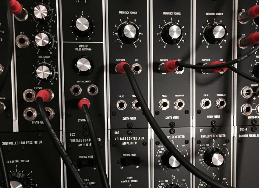
SYNTH-WERK is the result of a passion for synthesizer, elec-
tronic music, and the fascination for Dr. Bob Moog who laid
the foundation for music synthesizer technology along with
others about fifty years ago. That fascination that a Moog
modular system exerted likewise on musicians and audience
is still alive today almost 50 years later. For those who search
for the new sound, from back then to today, a modular system
is the gateway to complex and unique sounds.

SYNTH-WERK modules are based on original and unchan-
ged designs out of the 60s, utilizing the same hand assembly
methods used in the Moog Music factory in Trumansburg, NY
in the 60s. The modules are built just as the originals were,
by hand-stuffing and hand-soldering components to circuit
boards, and using traditional wiring methods. We are using
only high precision and selected components combined with
vintage NOS components.

The faceplates are etched as the original Moog® modules.
All modules follow the moog format ( 5U industry standard) and
come with the standard „.com“ connector for easy integration
in existing systems. The modules work with supply voltages of
+15/-15 Volt. All modules can be modified to work on the moog
standard of +12V and -6V, e.g. to be used in a Moog system
and on the internal power supply.

All modules are handcrafted with passion in Munich, Germany.
MODULES

Each module has its own power regulation
to +12/-6 Volt, except for the SW901AB/
SW921AB Oscillator Bank.
The power regulation for the SW901AB/
SW921AB is done on the 901A/ 921A
which supplies the 901B/921B`s.
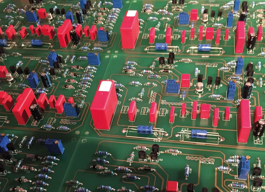
SW 901 OSCILLATOR

FUNCTION DESCRIPTION
The SW901 Voltage-Controlled Oscillator is a wide-
range generator of repetitive waveforms, the frequency
of which is controlled by the sum of applied control vol-
tages. The total frequency span of the oscillator is 0,1
to 15.000 Hz in six overlapping ranges. Four waveform
outputs are available: sawtooth, triangular, sine and
pulse. The width of the pulse waveform is continuously
variable, by means of a front panel potentiometer, from
complete symmetry to 8.1 asymmetry. One fixed and
one variable output are available for each waveform.

TECHNICAL SPECIFICATION
Number of control inputs:     3
Impedance:                    100k ohm
Characteristic:               1V/Octave
Waveforms:                    Sinewave / Sawtooth / Pulse / Triangular available simultaneously
Impedance of fixed outputs:   600 ohm
Level of outputs:             0,5 V RMS
Impedance of vari. outputs:   1500 ohm
Level of vari. outputs:       0 - 0,5 V RMS
Power Requirements:           +/-15 Volt at + 65 mA / - 55 mA
SW 901 AB OSCILLATOR BANK

FUNCTION / DESCRIPTION
The SW901A Oscillator Controller and the SW901B Oscillator
are, respectively, the controlling and the oscillating / wave-
shaping sections of the SW901 Voltage Controlled Oscillator.
The separation of the functions of the SW901 into two modu-
lar instruments allow the assembly of a bank of oscillators,
all of which are controllable from one controller.
The SW901A panel contains the control voltage input jacks
and potentiometer which vary the frequencies of all the
controlled oscillators simultaneously. The SW901B panel
contains frequency range controls and fixed level output
jacks for each waveform. One controller may control up to
7 Oscillators. A bank of oscillators in which the intervals
between the frequencies remain constant as the frequencies
themselves are varied obviously has great musical value.

TECHNICAL SPECIFICATION
SW 901 A
Number of control inputs: 3
Impedance:                100k ohm
Characteristic:           1V/Octave
SW 901 B
Number of outputs:      4 Sinewave / Sawtooth / Pulse / Triangular
Impedance of outputs:   600 ohm
Level of outputs:       0,5 V RMS
Power Requirements:     +/-15 Volt at + 120 mA /- 90 mA
                        All connected SW 901B´s are supplied from SW 901A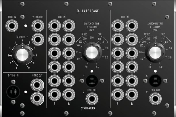
SW 921 OSCILLATOR

FUNCTION DESCRIPTION                                           MUSICAL APPLICATION
The SW921 Voltage Controlled Oscillator is a                   Besides the basic musical applications of a
variable waveform generator which produces                     Voltage Controlled Oscillator the SW921 offers
frequencies ranging from 0,01 to 40.000 Hz. Four               voltage controlled rectangular width which will
waveforms are available: sine, triangular, saw-                vary the harmonic structure of the rectangular
tooth and rectangular with variable duty cycle.                waveform and provide constant timbre chang-
Both fixed and variable levels can be obtained                 es within the oscillator, when controlled with
from front panel output jacks.Voltage controlled               a low frequency control voltage from another
rectangular width is set by a knob and with                    oscillator. An interesting phase cancellation
accompanying voltage input jacks. Clamping                     effect is created when a voltage controlled
point (waveform reset control) may be set by a                 rectangular waveform is added to the sawtooth
knob and accompanying trigger inputs. Multiple                 waveform from the same oscillator.
frequency control inputs can be plugged into
this module in parallel. This module functions
as both an audio or control voltage generator.

TECHNICAL SPECIFICATION

Characteristic:                   1V/Octave
Impedance:                        100k ohm
Number of control inputs:         3
Waveforms:                        sinewave / sawtooth / rectangular / triangular available simultaneously
Impedance of fixed level outputs: 800 ohm, except rectangular 50 ohm
Level of outputs:                 approx. 0,6 V RMS
Level of auxiliary outputs:       approx. 2,5V RMS
Power requirements:               +/-15 Volt at at +/- 50 mA
SW 921 AB OSCILLATOR BANK

FUNCTION DESCRIPTION
The SW921A Oscillator Driver is a control voltage processor
which runs associated SW921B oscillators through internally
wired connections. The SW921B generates frequencies from
1Hz to 40kHz minimum. This oscillator generates both sub-au-
dio and audio frequencies for control and audio signal use.
Fixed level outputs for sine, triangle, sawtooth and rectangular
waveforms are available. DC Modulate is a linear frequency
control input, AC Modulate input is a capacitor coupled circuit.
SW921B Oscillators may be phase locked together via the
Synch Input Jack and the associated three position Synch
Switch. A sawtooth waveform is recommended for best
synchronization results.

TECHNICAL SPECIFICATION
SW 921 A                            Synchronisation: Nominal input level -4 dBm
Impedance: 100k ohm                 Mode Switch: Center position defeats
Characteristic: 1V/Octave           synchronization. Strong position causes
Impedance: 100k ohm                 oscillator to lock onto harmonic or sub-har-
                                    monic signal. Weak position reduces locking
SW 921 B                            strength by a factor of 4.
Number of outputs: 4 Sinewave/      Power Requirements: +/-15V at +120mA/-
Sawtooth/ Rectangular/ Triangular 120mA.
Impedance of outputs: 1k ohm
                                    All connected SW921B´s are supplied from
Level of outputs: 0,6 V RMS         SW921A.
DC/AC Modulate: Linear FM / AC
Modulate input signal is rolled off
below 5 Hz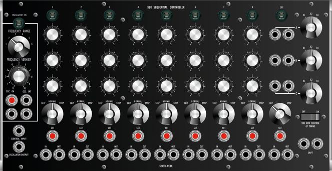
SWCP3 MIXER & SWCP3H MIXER

             FUNCTION DESCRIPTION                                   MUSICAL APPLICATION
             The SWCP3 module is a 4 x 1 mixer with positive and    The four channel mixer is useful for combining several
             negative outputs and a maximum gain of 2. This mixer   signals to form a single output. Audio signals from
             can combine both AC and/or DC voltages.                up to four different sources can be varied in relative
                                                                    volume before processing the mix through filters or
             The SWCP3H half size module has has the same
                                                                    amplifiers for a final result. Control voltages can be
             function like the SWCP3 plus a multiple in addition.
                                                                    mixed, attenuated and phase inverted before being in-
                                                                    troduced into a voltage controlled module. In addition,
                                                                    the CP3 mixer can be used for phase cancellation of
                                                                    complex sounds, e.g. if two or more signals with simi-
                                                                    lar frequency content are combined at opposite phase
                                                                    relationships and for feedback where the output of
                                                                    the mixer is sent directly back to an input of the CP3
                                                                    mixer.

                                                                    TECHNICAL SPECIFICATION
                                                                    Input Impedance:      25k ohm
                                                                    Output Impedance:     600 ohm
                                                                    Gain:                 x2 maximum
                                                                    S/N Ratios:           > 60 dB
                                                                    Outputs:              positive and negative outputs
                                                                    Power Requirements:   +/-15 Volt at +/- 30 mA
SWCP3H-SWITCH FUNCTION DESCRIPTION This CP Module has the same functionality like SW CP3 but in addition it containes routing switches for 4 external CV´s to the above Oscillator Bank like on the SW 3P-2020.
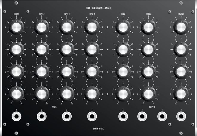
SW 984 FOUR CHANNEL MATRIX MIXER

FUNCTION DESCRIPTION                                      MUSICAL APPLICATION
The SW984 Four Channel Matrix Mixer is an AC cou-         The SW984 Mixer serves as a final audio summing
pled 4-input, 4-output matrix with bass and treble tone   device for up to four different inputs. Outputs can feed
controls for each output channel. Each input has a        any line level monitor or recording system. Optimum
separate attenuator for each of the four output chan-     impedance match is 10k ohm or less. The multiple in-
nels. Thus, a matrix of 16 input attenuators provides     puts and outputs of this module serve as good mixing
maximum channel separation, or variable combina-          point for external sound processors which will modify
tions of volume balance. Tone controls for each of the    or add echo to the synthesizer signal before entering
output channels can attenuate or emphasize bass or        the recording or monitoring system.
treble signals. Flat signal response is achieved with
the control settings kept at “5” on the potentiometers.
These are 2-pole active tone controls.
SW 984 FOUR CHANNEL MATRIX MIXER

TECHNICAL SPECIFICATION
Input Impedance:    25k ohm
Output Impedance:   5k ohm
Gain:               approx. x 1,25
S/N Ratios:         > 65 dB
Inputs:             Four input potentiometer per channel,
                    AC coupled
Outputs:            4, AC coupled
Power Requirements: +/-15 Volt at +/- 75 mA
SW 904 A VOLTAGE CONTROLLED LOW PASS FILTER
FUNCTION DESCRIPTION potentiometer is determined by the Frequency
Range switch, which moves the frequency
SW904A Voltage-Controlled Low Pass Filter
cutoff range in twooctave steps.
attenuates frequencies above the fixed control
voltage cutoff point at a rate of 24 dB per oc-
tave. The cutoff frequency is voltage controlled MUSICAL APPLICATION
through the control input jacks. The sum of the The Voltage Controlled Low Pass Filter is one
applied control voltages doubles the frequency of the building blocks of analog synthesis. The
of the cutoff point for each one Volt increase. characteristic upper spectral sweep found
The regeneration potentiometer varies the in wind instruments articulation is simulated
amount of internal feedback, creating a resonant utilizing this filter and the DC voltage supplied
peak at the cutoff frequency. This resonant peak by an Envelope Generator with each trigger
will break into oscillation at clockwise settings from a controller. Virtually, every instrumental
of the regeneration potentiometer, creating a simulation can use this filter arrangement as
voltage controlled sine wave generator. The part of its overall patch. The lowpass filter is a
fixed control voltage potentiometer covers a 12 key module in creating widely varying timbres
Volt (octave) range. The overall range of the FCV via subtractive synthesis.
TECHNICAL SPECIFICATION
Cutoff Frequency fc range:SW 904 B VOLTAGE CONTROLLED HIGH PASS FILTER
FUNCTION DESCRIPTION MUSICAL APPLICATION
The SW904B Voltage Controlled High Pass Filter The Voltage Controlled High Pass Filter is
attenuates input signal frequencies below its most useful for altering the timbre of input
nominal cutoff setting. The attenuation below signals by deleting the predominance of the
FCV cutoff setting is 24 db/oct. As the fundament fundament partial in a complex tone. Voltage
is generally the loudest frequency component of control of this module often creates a spectral
a complex tone, deletion of the lowest frequency sweep radically different from those associat-
range can radically alter the timbre. The FCV ed with acoustic instruments. A thin or “tinny”
cutoff point is raised or lowered in octave per sound often results when using this filter. Low
volt control inputs. The Frequency Range switch frequency control voltages (10 – 20 Hz) can,
sets the overall range of frequencies covered if their gain is boosted from the nominal fixed
by the Fixed Control Voltage potentiometer. The level output of the 901 Oscillator, effect in a
Low range encompasses 4 Hz to 20 kHz, while the rattling or “scraping” sound (almost regard-
High range shifts 1,5 octaves up to 10 Hz through less of input signal).
50 kHz. Connected to the Low Pass Filter in parallel,
series, the High Pass Filter helps form band
pass and band reject filters.
TECHNICAL SPECIFICATION
Cutoff Frequency fc range: 1Hz to 50 kHz
Signal Input Impedance: 33k ohm
Signal Input Level: 0 dBm nominal, +10dBm max without clipping
Signal gain: 0 dB nominal
Cutoff slope: 24 dB per octave
Control Input Frequency Response: DC to 16 kHz
Control Input Impedance: 100k ohm
Number of control inputs: 3
Output Impedance: 680 ohm (AC coupled)
Power Requirements: +/-15 Volt at + 75 mA / - 50 mASW 904 C FILTER COUPLER FUNCTION DESCRIPTION SW904C Filter Couples is a connecting module which combines the functions of the 904A Lowpass and 904B Highpass Filters together. In the “off” position, the Highpass and Lowpass Filters are disconnected from the 904C and may be used independently. When switched to the “Brandpass” mode, Highpass and Low- pass Filters are coupled in parallel to process a central band of frequencies – deleting both bottom and top. The bandreject mode presents the inverse relationship, rejecting a central frequency band, and passing only the lowest and highest frequency com- ponents. Voltage controlled bandwidth and center frequency controls are included on the coupler. Bandwidth can be etended to three octaves with manual settings or control voltage. Center Frequency ranges from 5Hz to 20kHz, via manual or voltage controlled settings. When using the 904C for Bandpass or Bandreject filtering, the following standard settings should be obeserved: 904A Fixed Control Voltage = +6 904A Frequency range = 2 904B Fixed Control Voltage = -1 904B Frequency Range = low Note: Passband settings = Bandwidth knob plus control voltage. Notchwidth = Minus bandwidth knob minus control voltage.
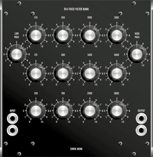
SW 914 FIXED FILTER BANK

FUNCTION DESCRIPTION
Similar in function to the Moog 907 Fixed Filter Bank, the SW914 Extended Range
Fixed Filter Bank is a non-voltage controlled modifier with 14 separate passband
controls: high-pass, low-pass, and 12 center frequency knobs. Each passband
range has an attenuation slope of 12 dB per octave above or below the center fre-
quency indicated.

MUSICAL APPLICATION
This Extended Range Filter Bank is highly useful for emphasizing or attenuating
frequency bands in the mid-range of hearing. Instrument simulation, especially
double reeds, is a major application for this module due to their varied resonances
in mid-range frequency bands. Varying frequency response in each of the half/
octave ranges, even slightly, will change the timbre of a tone as it is moved from
one region to the next. Radically different timbres can be overlapped from one
frequency range to another, by utilizing the 914 as a fixed cut-off filter. In one range,
a particular timbre may predominate when mixed with another. When the signal is
moved into a cut-off range, the non-filtered frequencies of the mix will assume
maximum importance.
SW 914 FIXED FILTER BANK

TECHNICAL SPECIFICATION
Signal Input impedance:    50k ohm
Signal Output impedance:   1k ohm
Signal Gain:               unity
Output Noise:              < 65 dB
Power Requirements:        +/-15 Volt at + 20 mA / - 10 mA
SW 907            FIXED FILTER BANK

FUNCTION DESCRIPTION
The SW907 and SW907A Fixed Filter Bank are non-voltage
controlled modifiers, who emphasize or reduce the gain of
the center frequency bands indicated on each of the eight
center potentiometers, in addition to the cutoff points set by
low pass and high pass filters at either frequency extreme.
A total of 10 overlapping LC networks are included.

TECHNICAL SPECIFICATION
Signal Input impedance:    10k ohm
Signal Output impedance:   680 ohm
Signal Gain:               unity
Output Noise:              < 65 dB
Power Requirements:        +/-15 Volt at + 20 mA / - 10 mA
SW 907 A   FIXED FILTER BANK

MUSICAL APPLICATION
The SW907 and SW907A Fixed Filter Bank are often referred to as formant fil-
ter because they can be set to emphasize or attenuate midrange frequencies,
which fall within a particular band, no matter how the frequencies of the signal
are moved. Like many acoustic instruments, a characteristic set of formants,
are always a part of the resultant output (given a particular complex waveform).
Emphasized bands of this sort are particularly evident with double reed instru-
ments. Thus, this filters are part of the patch for these simulations. In addition,
completely different timbres can be set up for different ranges of the same tone,
if the output of the filter is recombined with unfiltered frequencies at different
levels.

TECHNICAL SPECIFICATION
Signal Input impedance:    10k ohm
Signal Output impedance:   680 ohm
Signal Gain:               unity
Output Noise:              < 65 dB
Power Requirements:        +/-15 Volt at + 20 mA / - 10 mA
SW 902 VOLTAGE-CONTROLLED AMPLIFIER

FUNCTION DESCRIPTION                                                  MUSICAL APPLICATION
The SW902 Voltage-Controlled Amplifier is a differ-                   The SW902 Voltage-Controlled Amplifier is used in
ential input and output circuit which gives an overall                any circumstances where variable gain is desired for
voltage gain of 2 (6 dB) when manual control poten-                   gating or modulating AC or DC voltage sources. Ar-
tiometer is at maximum, or when a control voltage of                  ticulation of a tone or sound, utilizing oscillators, con-
6 Volts is applied to the control input. Two modes of                 trollers, envelope generators and the VCA is the basic
gain are available: Linear and exponential.                           traditional patch around which most performance
                                                                      oriented synthesizers are based. In addition to DC
                                                                      control voltage, the VCA can be controlled by varying
                                                                      voltages (AC) from sources like the SW 901 Oscillator.
                                                                      Slowly varying control voltages (2-9 Hz) can create
                                                                      tremolo or echo like effects upon an audio signal.
                                                                      Audio control frequencies create sidebands with
                                                                      often clangorous effects, usefull for a variety of audio
                                                                      timbres and percussive sounds. The inverting outputs
                                                                      of the VCA can be useful for spatial modulation, signal
                                                                      inverting of control voltages, controlling two oscil-
                                                                      lators in contrary motion with a single control signal
                                                                      and various amplitude sampling arrangements.
TECHNICAL SPECIFICATION
Signal Input Frequency Response:    DC to 50 kHz
Signal Input Impedance:             10k ohm nominal
Control Input Frequency Response:   DC to 50 kHz
Control Input Impedance:            100k ohm nominal
Number of control inputs:           3
Output Impedance:                   680 ohm
Power Requirements:                 +/-15 Volt at + 75 mA / - 40 mA
SW 911 ENVELOPE GENERATOR
FUNCTION DESCRIPTION MUSICAL APPLICATION
At the introduction of a V-trigger signal from an exter- The SW911 Envelope Generator completes one of the
nal source, the SW911 Envelope Generator produces most important musical functions: That of producing
a single voltage contour whose time/voltage variation a variable one-shot control voltage contour in time.
is determined by potentiometers T1, T2, T3, and a time This output is thus capable of controlling any voltage
constant sustaining level potentiometer (Esus). The controlled module – most notably a Voltage Controlled
release of the V-Trigger signal will direct the voltage Amplifier – resulting in the articulation of a single
contour to T3 (final decay) regardless of what stage sound. Keyboard controllers initiate a trigger on ev-
(T1, T2 or E) was in current operation. ery key, which is depressed in sequence specifically
to fire the envelope generator. Ribbon Controllers,
Sequencial Controller Complements and Envelope
Followers, all output V-trigger which initiate the ac-
tion of this module as well. Characteristic spectral
sweeps associated with the articulation of a note by
an acoustic instrument are simulated by utilizing the
Envelope Generator to control the frequency cutoff of
the SW 904A Low Pass Filter, SW 904B High Pass Filter
or other associated modules. With considerable at-
tenuation, the Envelope Generator can create tunable
glissandi when controlling a single oscillator. Envelope
Generators are used in association with the SW 911A
Dual Trigger Delay to create multiple or combined DC
TECHNICAL SPECIFICATION
voltage contour outputs.
Trigger Input: V-Trigger (internally converted to S-Trigger)
Time Range on T1, T2, T3: 2 msec to 10 sec
Peak DC output on Esus: 5,5 Volt
Power Requirements: +/-15 Volt at + 25 mA / - 20 mASW 911 A DUAL TRIGGER DELAY
FUNCTION DESCRIPTION MUSICAL APPLICATION
The SW911A Dual Trigger Delay is designed to be Standard synthesizer envelopes provide anywhere
used with 2 or more SW911 Envelope Generators. It from two to four DC voltage settings over a triggering
provides one or two time delays on an input trigger period. In practice, acoustically generated sounds
voltage – bound for the activation of an envelope have many variations of amplitude or filtration within a
V-trigger. Delay stops immediately upon termination of given articulation or generation. The use of a SW911A
input trigger. to couple envelopes together creates a much more
complex series of voltage variations for the synthesist
Three different modes of operation are available via to use for the articulation of each sound.
coupling mode switch:
OFF: Delays are activated independently through indi-
vidual trigger inputs
PARALLEL: Trigger input on top SW 911A activates
timing circuit on both simultaneously.
SERIES: Trigger input on top 911A activates top timing
circuit, then triggers second timing circuit upon delay
time of first.
TECHNICAL SPECIFICATION
Trigger Input: V-trigger (internally converted to S-trigger)
Trigger Output: V-trigger (internally converted from S-trigger)
Delay periodes: 2 msec to 10 sec
Power Requirements: +/-15 Volt at + 25 mA / - 20 mASW 912 ENVELOPE FOLLOWER
FUNCTION DESCRIPTION MUSICAL APPLICATION
The SW912 Envelope Follower produces two func- The SW912 Envelope Follower is an extremely useful
tions, which can be used separately or in conjunction. module for interfacing external sources with the many
The follower circuit signal input presents a control functions of the synthesizer, which require both control
voltage output (DC) proportional to the average am- voltages and triggers to function. Filter or amplitude
plitude of the AC input signal. The second function, a variations can be achieved by routing the audio signal
Schmitt trigger, generates a V-trigger above a thresh- to both the processing modules and the Envelope Fol-
old voltage (comparator), when a slowly varying or lower. The control voltage of the follower circuit can
DC voltage is introduced at the control input jack. The raise or lower the cutoff frequency of a voltage con-
normalling of the control output of the follower circuit trolled filter. At the same time, the Envelope Generator
to the control input of the Schmitt trigger circuit allows can be triggered by the V-trigger output of the follower,
both control voltage and trigger to be generated from a causing a VCA to gate the original signal above a cer-
single variable source. tain amplitude. This latter operation can be very useful
as a noise gate, closing down an audio signal when
the level drops below a nominal setting. One further
use involves generating random triggers from the En-
velope Follower by utilizing white noise or pink noise
as a signal input and carefully setting the threshold
level to achieve a speed of trigger selection.
TECHNICAL SPECIFICATION
Nominal Input impedance: 100k ohm
Nominal Output impedance: 69k ohm
Control Input impedance: 61k ohm
Control Output: Connected to control input internally
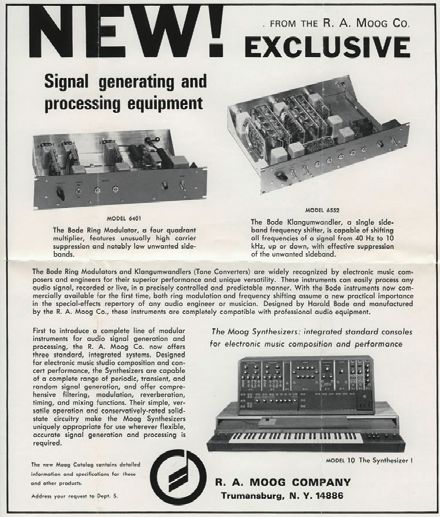
Power Requirements: +/-15 Volt at + 40 mA / - 35 mASW 6401 M BODE RINGMODULATOR
FUNCTION DESCRIPTION MUSICAL APPLICATION
A ringmodulator is an analog sound modification It was probably electronic music pioneer Karlheinz
system that takes two inputs, one a program-signal Stockhausen’s use of the ringmodulator that inspired
and the other a carrier frequency, being and produc- an entire generation of rock musicians. Stockhausen’s
es a single output. The program signal is normally a Mixture (1964), for example, was written for a ring
waveform produced by the output from a microphone modulated symphony orchestra. Ringmodulation is
(voice) or any other source of signal, while the carrier often used to simulate the sounds of tuned percussion
signal is normally a sine wave. The function of the instruments that produce inharmonic frequency spec-
ring modulator is to produce the sum and difference tra, such as bells and chimes. It can also produce tim-
frequencies of the program signal and carrier signal. bres that are difficult to achieve by any other method
The SW 6401M is based on the original design of of synthesis. Among all signal processors, the multi-
Harald Bode from plier-type ring modulator takes a unique position since
1967. The design is it is capable of converting existing sounds into new
a circuit involving a sounds with entirely different overtone spectra that do
ring of diodes and not resemble the original acoustical phenomena.
transformers forming
a four quadrant mul-
tiplier. To accomplish
TECHNICAL SPECIFICATION
a one unit module,
the transformers Input Impedance program input: 47k ohm
Input Impedance carrier input: 47k ohm
UTC-A20 have been Output Impedance: 680 ohm
replaced by smaller Nominal Input Voltage: 1V RMS (higher levels will lead to
vintage UTC SO 15P distortion which can be an additional
transformers. The interesting effect)
Gain: approx. 0
diodes are original Frequency range: 0,15 kHz to 20 kHz
NOS 1N485A. Power Requirements: +15 Volt at + 90 mASW 6401 M BODE RINGMODULATOR HARALD BODE Harald Bode was born in 1909 in Hamburg, Germany. At the age of 18 he lost his parents and started study- ing, and graduated from the University of Hamburg in 1934. In 1935, he began his pioneering work in the field of electronic musi- cal instruments, and with funding support provided by Christian Warnke, his earliest work was completed in 1937. Warbo Formant Organ, an archetype of to- day’s polyphonic synthesizer, was a four voice key-assignment keyboard with two formant filters and dynamic envelope controller. Eventually it went into commercial production by a factory in Germany, and it became one of the earliest polyphonic synthesizer products, along with Novachord by Hammond. In 1959-1960, Bode de- veloped modular synthesizer and sound processors, and in 1961, he wrote a paper exploring the advantages of newly emerging transistor technology over older vac- uum tube devices; also he served as AES session chairman on music and electron- ic for the fall conventions in 1962 and 1964; after then, his ideas were adopted by Robert Moog, Donald Buchla and others. After retiring from the chief engineer of Bode 6401 Ring Modulator 1967 as part of the Moog Bell Aerospace in 1974, he composed TV-advertising spots and gave live concerts. Music product range. Also in 1977, Harald was invited as a chief engineer of the Norlin/Moog Music after Robert Moog left. He died in New York, NY, United States 1987.
SW 1630 BODE FREQUENCY SHIFTER

FUNCTION DESCRIPTION                                      MUSICAL APPLICATION

A frequency shifter is an audio signal modifier which     In shifting the components of the input
shifts the entire frequency spectrum of the applied       audio spectrum by a given amount,
signal by a given amount. The Model SW 1630 Bode          the SW 1630 Bode Frequency Shifter
Frequency Shifter allows the amount of shift to be        changes the original ratios between
accurately and continuously controlled over a span        the overtones and other frequency
of -5000 Hz to +5000 Hz, utilizing voltage and/or manu-   components of the input signal. Rather
al control. The relationship between the control volt-    than being a transposing device, this
age sum and the amount of shift may be either linear      instrument is a means for achieving an
or exponential. Up-shifted and down-shifted outputs,      extremely wide variety of tone color
as well as a continuously variable mixture of the         modification. Whether the amount of
two, are available simultaneously and independently.      frequency shift is large or small, static
Variable threshold squelch and zeroadjust fine tuning     or time varying, or whether the input
controls are provided.                                    signal is simple or complex, the pro-
                                                          cessed outputs will generally be musi-
The Model SW 1630 Bode Frequency Shifter changes          cally interesting.
the ratios between the frequency components of an
audio spectrum, thus producing a variety of novel
sound quality transformations. Applications include a     SW 735 BODE FREQUENCY SHIFTER
wide variety of tone color modification, P.A. feedback
suppression, linear frequency modulation, novel tape      The Model SW 735 is the rack
feedback effects, and the generation of dynamically       version of the Bode Frequency Shifter
varying clangorous tones.                                 including a power supply. From an
                                                          electrical point of view it is identical
                                                          to the Model SW 1630.
SW 1630 BODE FREQUENCY SHIFTER TECHNICAL SPECIFICATION Nominal Input Impedance: 50k ohm Nominal Input Level: +2dBm Frequency Range: 30Hz to 16kHz Nominal Output/Input gain: Unity Power requirements: +/-15 Volt at + 100 mA / -100 mA Less than 0.1% total hum and noise Variable threshold squelch minimizes apparent carrier bleedthrough due to input signal background noise Accurately shifts input signals over the audio frequency range of 30 Hz – 16 kHz Amount of shift is continuously variable from -5 kHz, through zero to +5 kHz Amount of shift is accurately voltage variable – either linear or exponential control mode is available Less than 1% total unwanted modulation and distortion products
SW 903 A RANDOM SIGNAL GENERATOR

FUNCTION DESCRIPTION                                         MUSICAL APPLICATION
The Random Signal Generator produces continuous              Almost all acoustically generated sounds one hears,
bursts of random frequencies and waveshape from              at all times, contain some amount of random noise.
approximately 25 Hz to 20 kHz. Two types of energy           Most obvious are wind, surf and thunder. Some
distribution are provided: White noise and pink noise.       amount of unpitched sound is evident in just about
The former distributes amplitude evenly throughout           every environment. Acoustic instruments produce
the indicated audio spectrum. The latter reduces the         varying amount of unpitched sound along with specif-
amplitude of each frequency increment proportionally         ic notes. Drums, Tam-Tam, blocks, gongs and various
to produce equal energy per octave. Pink noise, thus,        other percussion instruments are all unpitched instru-
sounds “lower” in pitch to the ear.                          ments. White and pink noise provides the synthesist
                                                             with a basic source for simulating these instruments,
                                                             as well as a source for recreating “environments”.
                                                             As an audio source, the Random Signal Generator is
                                                             most often used in connection with filters to create a
                                                             desired frequency band or correct spectral sweeps.
                                                             The Random Signal Generator also provides a source
                                                             of control voltage for filters, oscillators, amplifiers and
                                                             other voltage controlled modules, producing interest-
                                                             ing random modifications.
                                                             As a source for the Envelope Follower, random trig-
                                                             gers can be produced as well as slowly varying DC
                                                             voltage contours (with slow response time). Noise is
TECHNICAL SPECIFICATION                                      also useful as a control source for sample and hold
                                                             circuits and random sequencer triggers.
Average level white noise: -10 dBm (30 Hz – 20 kHz)
Average level pink noise: -4 dBm (30 Hz – 20 kHz)
Power Requirements:        +/-15 Volt at + 35 mA / - 30 mA
SW REVERSIBLE ATTENUATOR / SW 995 ATTENUATORS / SW 994 MULTIPLES FUNCTION DESCRIPTION SW REVERSIBLE ATTENUATOR The Reversible Attenuator processes a control voltage destined for the CV input of a specific module. As the knob rotates counter-clockwise from 10 to 0, the proportion of the control voltage applied to the input jack that appears at the output jack decreases from 100% to 0%. As the knob rotates past 0 toward -10, the output voltage will rise to 100% of the input voltage but the polarity will be reversed. FUNCTION DESCRIPTION SW 995 The SW995 Attenuators panel consists of three „passive circuits“, each made of a 25k potentiometer between input and output. The signal input to the top attenuator is chained to the bottom two in series. Introduction of a patch cord into middle or bottom input breaks the normalling system. Attenuators reduce the gain or amplitude of any applied input signal, con- trol or audio. FUNCTION DESCRIPTION SW 994 The dual multiple panel consists of two sets of four jacks. Each set of jacks has been wired together. The multiple is a “device” which permits multiple distribution of one signal to several different places. This process is often called signal splitting. Multiples are used for many purposes; from linking two patch cords together, sending a single signal to several differ- ent modules at the same time.
SWCP MULTIPLES & ATTENUATORS

FUNCTION DESCRIPTION / APPLICATION

The multiple part consists of three sets of four jacks.
Each set of jacks has been wired together. The multiple
is a “device” which permits multiple distribution of one
signal to several different places. This process is often
called signal splitting. Multiples are used for many pur-
poses; from linking two patch cords together, sending a
single signal to several different modules at the same
time.
The Attenuator part consists of three „passive cir-
cuits“, each made of a 25k potentiometer between
input and output. The signal input to the left hand
attenuator is chained to the right hand two in series.
Introduction of a patch cord into middle or right hand
input breaks the normalling system.
Attenuators reduce the gain or amplitude of any ap-
plied input signal, control or audio. Moving clockwise
from zero gain to unity gain with input, these attenu-
ators can be used for reducing the effect of a control
upon a voltage controlled module, providing up to
three variable outputs from a single source input or
reducing the gain of an entire signal complex.
SW 905 REVERBERATION UNIT

FUNCTION DESCRIPTION / APPLICATION
The SW905 Reverberation Unit utilizes a dual spring-
type acoustic delay line to produce a succession of
decaying echoes of an audio signal. A single panel
control determines the ratio between the amounts of
reverberated and non-reverberated signals that appear
at the output jack.

MUSICAL APPLICATION
When a dynamically varying signal is applied to the
input of the SW905, the output will consist of a series of
closely spaced echoes, the subjective effect of which
is similar to that of reverberation of sound. When a
static signal is applied to the input of the SW905, the
output will also be static. The SW905 will perform in
this application like a formant filter, strongly coloring
the timbre of any signal with appreciable harmonic
content.

TECHNICAL SPECIFICATION
Power Requirements: +15 Volt at +20 mA
SW 923 RANDOM NOISE/FILTER

FUNCTION DESCRIPTION
The White and Pink noise outputs of the 923 Random
Noise/Filter module produces continuous bursts of
random frequencies and wave shape throughout the
audio spectrum.
The two manual sweep filters, Lowpass and Highpass,
are single pole circuits with a frequency cutoff slope
of 6dB/octave.

MUSICAL APPLICATION
Like the 903A Random Signal Generator, white and pink
noise are a fundamental sound source for non-pitched
sounds, and virtually all environmental/acoustic ambi-
ences.

TECHNICAL SPECIFICATION
Average output level White:                   -10dBm (30Hz - 20 kHz)
                     Pink		                    -4dBm
Lowpass Filter Attenuation slope above fc:    6db/octave
Frequency Range:		                            10Hz -10kHz
Highpass Filter Attenuation slope below fc:   6dB/octave
Frequency Range:                              10Hz -10kHz

Power Requirements: 		                        +/-15V at +/- 35 mA
SW 960 SEQUENTIAL CONTROLLER FUNCTION DESCRIPTION MUSICAL APPLICATION The SW 960 Sequential Controller has a wide variation In addition to the regular functions of the sequencer of functions, both as an independent module and in the SW 960 sequencer can be driven at audio speeds combination with the SW 961 Interface and SW 962 to form a “graphic waveform generator“ great varia- Sequential Switch. The sequence module consists of a tions of timbre can be obtained by varying the voltage voltage controlled clock oscillator which drives three of each step in the sequence. Separate triggers for rows of eight steps each. Voltage range switches for each stage can trigger the alteration of totally different each row determine the DC voltage range of each pot. sounds. In combination with the SW 961 Interface, Jacks for trigger inputs and outputs appear below highly flexible rhythm tracks can be created with each column. Timing control for the eight steps is ac- different instrumental sounds alternating on different complished via the Third Row Control of Timing switch. beats. TECHNICAL SPECIFICATION Clock Oscillator Frequency Range: 0,1Hz to 500Hz, VC 1V/Oct Waveform Out: Rectangular Output Impedance: 4,7 k nominal Input Impedance: 100 k nominal (control input) Oscillator on/off trig: > 3 Volt trigger Ext.Shift input: > 3 Volt trigger V-triggers: > 3 Volt trigger in/Out Control Voltage Outputs: X1: 2 Volts X2: 4 Volts X3: 8 Volts Power Requirements: +/-15 Volt at 300 mA / 40 mA
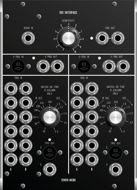
SW 961/961CP INTERFACE

                         FUNCTION DESCRIPTION                         MUSICAL APPLICATION
                         Four independent circuits are found          The SW 961 Interface module serves
                         on the SW 961 Interface: One Audio-In        as an „intermediate“ operations
                         to V-trigger Out circuit, one S-trigger In   module, useful for converting one
                         to V-trigger Out circuit and two V-trig-     type of signal to another – for purposes
                         ger In to S-Trigger/V-trigger Out cir-       of switching or controlling a particular
                         cuits. All interface circuits may be         function. The Audio-to V-trigger sec-
                         used simultaneously, in combination          tion of the 961 Interface is useful as a
                         or separately.                               trigger source.
SW 962/962CP SEQUENTIAL SWITCH FUNCTION DESCRIPTION The SW 962 Sequential Switch selects between two or three signal inputs, coupling one signal to the out- put at a time. A V-trigger pulse introduced to the Shift Input initiates the sequence.The sequential switch will alternate between stages one and two until a standard phone plug is patched into Signal Input Three. TECHNICAL SPECIFICATION SW 962/962CP Functional Requirements: V-Triggers: 3 Volt Pulse Power Requirements: +/-15 Volt at 120 mA / 10 mA TECHNICAL SPECIFICATION SW 961/961CP All V-triggers for entire module require (input) or generate (output) a 3 Volt pulse. Power Requirements:+15 Volt at 100 mA
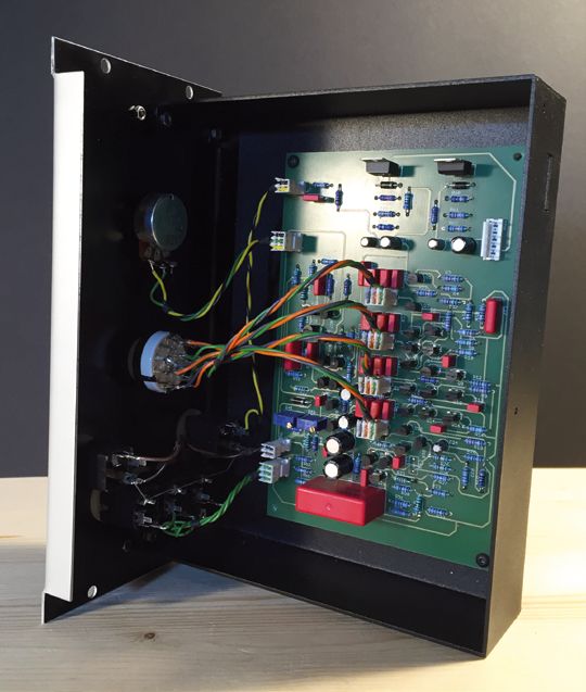
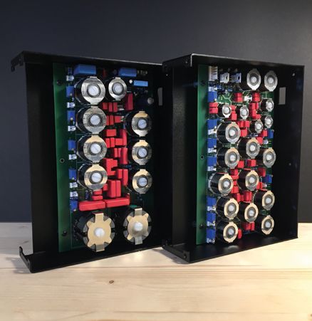
RESTAURATION
OF OLD MOOG SYSTEMS

Original Moog Modules are very rare and expensive
these days. Especially the 901A Oscillator controller
and 901B oscillator. If you have a single 901A and 901B
in your system and you wish to extend it to an oscil-
lator bank... No problem! We can replace the missing
modules by SYNTH-WERK modules and either retune
the whole oscillator bank to fullfill the original specifi-
cations when it has left the Trumansburg factory many
years ago, or we can adjust the SYNTH-WERK mod-
ules to the aged waveforms of the Moog 901B oscilla-
tors (see picture).
All SYNTH-WERK modules can be modified to run on
+12V and -6V. SW911 and SW911A can be modified to
run on S-Trigger, including Chinch-Jones connector.
CASES

You can choose between either a 8U mobile Tolex case
or a 10U wooden case. The wooden case is a hand-
some blend of birch wood and walnut.
We can also deliver every customer specific size of
cases.
„When you connect with an instrument, no matter of
what sort, there is an interaction that’s outside of what’s
actually going through your fingers. I hesitate to use the
word ‘spiritual’, but I’m absolutely sure that there is a
consciousness that we connect with.“                 Bob Moog

                                                                     SYNTH-WERK
                                                                   Gerhard Mayrhofer

                                                                   Lindenfelser Straße 5
                                                                 D-80939 Munich Germany
                                                                   Phone +491746660000
                                                                   mayrhofer@mac.com

                                                                  www.synth-werk.com
                                                                       © 2022

                                                                    Trademarks and logos
                                                                   are the property of their
                                                                     respective owners.
www.synth-werk.com
You can also read