Models 6-250 & 6-450 DAKE AIR-OPERATED HYDRAULIC PRESS - Dake Corp
←
→
Page content transcription
If your browser does not render page correctly, please read the page content below
DAKE AIR-OPERATED HYDRAULIC PRESS

                       Models 6-250 & 6-450
                                  INSTRUCTIONAL MANUAL

    WARNING!
Read and understand all instructions and responsibilities before operating. Failure to follow
safety instructions and labels could result in serious injury.

Dake Corporation                         Phone: 800.937.3253                  www.dakecorp.com
1809 Industrial Park Dr                   Fax: 800.846.3253
Grand Haven, MI 49417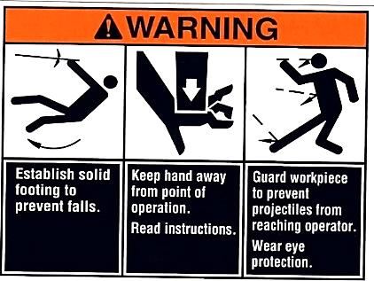
Dake Corporation
                                                                                            1809 Industrial Park Dr
                                                                                           Grand Haven, MI 49417
                                                                                               www.dakecorp.com

                                        TABLE OF CONTENTS

DAKE STANDARD LIMITED WARRANTY............................................................ 2
RETURN & REFUND POLICY .............................................................................. 4
SAFEGUARDING THE POINT OF OPERATION .................................................. 5
SPECIFICATIONS ................................................................................................ 6
SAFETY ................................................................................................................ 7
SET UP ................................................................................................................. 8
OPERATION ......................................................................................................... 9
MAINTENANCE .................................................................................................... 9
        LUBRICATION ............................................................................................. 9
TROUBLESHOOTING ........................................................................................ 10
EXPLODED VIEW & PARTS LIST ...................................................................... 12
ORDERING INFORMATION ............................................................................... 20

906250, 906450                                              1                                                REV012022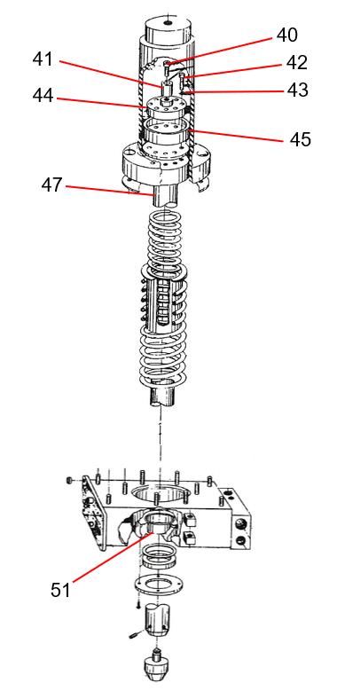
Dake Corporation
                                                                                  1809 Industrial Park Dr
                                                                                 Grand Haven, MI 49417
                                                                                     www.dakecorp.com

DAKE STANDARD LIMITED WARRANTY

Finished Machines
Dake warrants to the original purchaser the finished machine manufactured or distributed by it to be free
from defects in material and workmanship under normal use and service within 1 year (12 months) from
the delivery date to the end user.

Parts
Dake warrants to the original purchaser the component part manufactured or distributed by it to be free
from defects in material and workmanship under normal use and service within 30 days from the delivery
date to the end user.
The standard limited warranty includes the replacement of the defective component part at no cost to the
end user.

Sale of Service (Repairs)
Dake warrants to the original purchaser the component part repaired by Dake Corporation at the
manufacturing facility to be free from defects in material and workmanship under normal use and service
within 90 days from the return date to the end user, as it pertains to the repair work completed. The
standard limited warranty includes repair of the defective component part, at no cost to the end user.

Warranty Process
Subject to the conditions hereinafter set forth, the manufacturer will repair or replace any portion of the
product that proves defective in materials or workmanship. The manufacturer retains the sole right and
option, after inspection, to determine whether to repair or replace defective equipment, parts or
components. The manufacturer will assume ownership of any defective parts replaced under this
warranty.
All requested warranty claims must be communicated to the distributor or representative responsible for
the sale. Once communication has been initiated, Dake Customer Service must be contacted for
approval:
        Phone: (800) 937-3253
        Email: customerservice@dakecorp.com

When contacting Dake, please have the following information readily available:
      - Model #
      - Serial #
      - Sales Order #

Purchasers who notify Dake within the warranty period will be issued a Case number and/or a Return
Material Authorization (RMA) number. If the item is to be returned per Dake’s request, the RMA number
must be clearly written on the exterior packaging. Any item shipped to Dake without an RMA will not be
processed.

906250, 906450                                       2                                           REV012022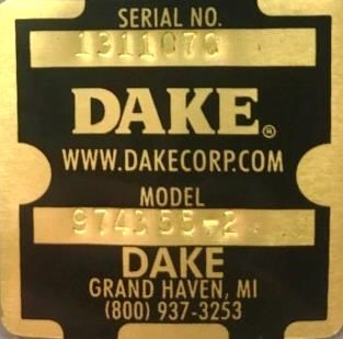
Dake Corporation
                                                                                 1809 Industrial Park Dr
                                                                                Grand Haven, MI 49417
                                                                                    www.dakecorp.com

Warranty Exceptions:
The following conditions are not applicable to the standard limited warranty:
        (a) Part installation or machine service was not completed by a certified professional, and is not
            in accordance with applicable local codes, ordinances and good trade practices.
        (b) Defects or malfunctions resulting from improper installation or failure to operate or maintain
            the unit in accordance with the printed instructions provided.
        (c) Defects or malfunctions resulting from abuse, accident, neglect or damage outside of prepaid
            freight terms.
        (d) Normal maintenance service or preventative maintenance, and the parts used in connection
            with such service.
        (e) Units and parts which have been altered or repaired, other than by the manufacturer or as
            specifically authorized by the manufacturer.
        (f) Alterations made to the machine that were not previously approved by the manufacturer, or
            that are used for purposes other than the original design of the machine.

906250, 906450                                      3                                           REV012022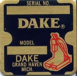
Dake Corporation
                                                                           1809 Industrial Park Dr
                                                                          Grand Haven, MI 49417
                                                                              www.dakecorp.com

RETURN & REFUND POLICY
Thank you for purchasing from Dake! If you are not entirely satisfied with your purchase, we are
here to help.

Returns

All Dake manufactured / distributed machines, parts and couplings include a 30-day return
option. These policies are valid from the date of final shipment to the end user.

To be eligible for a return, the item must be unused and in the same condition as received.

All requested warranty claims must be communicated to the distributor or representative
responsible for the sale. Once communication has been initiated, Dake Customer Service must
be contacted for approval:

       Phone: (800) 937-3253
       Email: customerservice@dakecorp.com

Once the return request has been approved by Customer Service, a representative will supply a
Return Material Authorization (RMA) number. The returned item must have the provided RMA
number clearly marked on the outside packaging. Any item received without an RMA number
clearly visible on the packaging will not be processed.
An RMA number can only be provided by the Dake Customer Service team and must be
obtained prior to the return shipment.

Refunds

Once the item has been received and inspected for damages, a representative will notify the
requestor referencing the provided RMA number.

If the return is approved, a refund will be issued to the original method of payment, less a 20%
restocking fee. The restocking fee may be waived if an order is placed at the time of return with
like-value merchandise.

Transportation costs are the responsibility of the end user and will not be credited upon return
approval.

Any item that is returned after the initial 30 days or has excessive/obvious use will not be
considered for a full refund.

906250, 906450                                   4                                       REV012022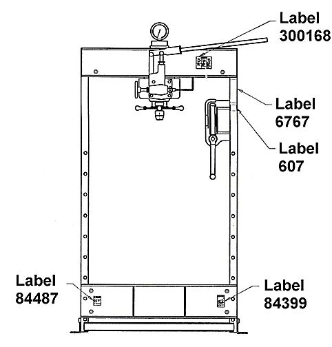
Dake Corporation
                                                                                  1809 Industrial Park Dr
                                                                                 Grand Haven, MI 49417
                                                                                     www.dakecorp.com

                 SAFEGUARDING THE POINT OF OPERATION
                           ANSI B11.2 - Hydraulic Power Presses -
                     Safety Requirements for Construction, Care, and Use

It is important that Dake press users have a clear understanding of their responsibility involving the care
and use of their Dake hydraulic press, including point-of-operation safe guards. Dake strongly
recommends that Dake press users obtain a copy of the current American National Standard Institute
(ANSI) B11.2 standard, for a more complete understanding of their responsibilities.

ANSI B11.2 states the following, relative to point of operation safeguarding:

“Normally, only the employer (press user) can determine the requirements of the press productions
system components, including the dies and methods for feeding. Therefore, the employer is ultimately
responsible to designate and provide the point-of-operation safeguarding system.”

The standard also discusses additional responsibilities of the employer. Some of the key responsibilities
are:
• The employer is responsible for the safety, use, and care of the hydraulic power press production
    system.
• The employer is responsible to consider the sources of hazards for all tasks to be implemented on
    the hydraulic power press production system.
• The employer is required to eliminate, or control identified hazards in the scope of their work activity.
• The employer is responsible for the training of personnel, caring for, inspecting, maintaining, and
    operating hydraulic press production systems to ensure their competence.
• The employer is responsible to provide and ensure that point-of-operation safeguarding is used,
    checked, maintained, and where applicable, adjusted on every production operation performed on a
    press production system.

A complete and current copy of the ANSI B.11.2 standard can be obtained by contacting the following:

                                  American National Standards Institute
                                            1430 Broadway
                                         New York, NY 10018

                          AMT – The Association for Manufacturing Technology
                                        7901 Westpark Drive
                                         McLean, VA 22102

906250, 906450                                       5                                           REV012022
Dake Corporation
1809 Industrial Park Dr
Grand Haven, MI 49417
www.dakecorp.com
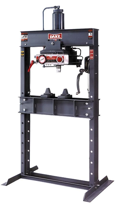
SPECIFICATIONS
Model 6-250 Model 6-450
Number 906250 906450
Capacity 50 tons 50 tons
Width between uprights 32-3/4” 32-3/4”
Width between table channels 7-1/4” 7-1/4”
Minimum ram to table 5” 5”
Maximum ram to table 40” 40”
Ram travel 10” 10”
Horizontal work head travel 13-1/4” 13-3/4”
Height 87” 87”
Weight 1,100 lbs 1,150 lbs
Base 43-1/2” x 36” 43-1/2” x 36”
Ram advance speed 65 ipm 55 ipm
Pressing speed 3 ipm 5 ipm
Number or pumps 1 2
Air pressure 90-125 psi 90-125 psi
In the space provided record the serial number and model number of the machine. This
information is only found on the black and gold Dake tag shown below. If contacting Dake this
information must be provided to assist in identifying the specific machine.
Serial No.
Model No.
Install Date:
906250, 906450 6 REV012022Dake Corporation
1809 Industrial Park Dr
Grand Haven, MI 49417
www.dakecorp.com
SAFETY
This is the safety alert symbol. When you see this symbol on your press be alert to the
potential for personal injury.
Employer is responsible to perform a hazard/PPE assessment before work activity.
Follow recommended precautions and safe operating practices.
Label Placement View
Label Part No. Label Part No. Label Part No.
84487 84399 84395
Label Part No.
607 Label Part No.
Label Part No. 300168 76462
Label Part No.
7355
Additional Warnings:
• Carefully read all safety messages in these instructions and on your press safety signs.
• Keep safety labels in good condition. Replace missing or damaged safety labels.
• Do not alter this press from its original state.
• Only use Dake original parts.
• This machine is intended to be operated by one person. This person should be conscious
of the press ram movement not only for themselves but also for other persons in the
immediate area.
• Tag out procedures must be followed by authorized employees as per OSHA.
906250, 906450 7 REV012022Dake Corporation
1809 Industrial Park Dr
Grand Haven, MI 49417
www.dakecorp.com
SET UP
For shipping convenience some of the parts are not assembled. Assemble these parts in the
following order:
1. Bolt the base angles to uprights using four provided bolts and nuts. Ensure that the base
angles are against the stops on the uprights. The press should set on a level floor with
base angles touching the floor at all points, use shims when necessary.
2. Connect airline in to street elbow (Item 136) at the right side of the control block. Avoid
restrictions in air supply line to ensure ampler air to the air motor. For maximum
performance the air supply line should be 1/2” pipe if the distance from the compressor to
the press is 0-30 feet, 3/4” line for 30-60 feet, and 1” if distance is greater then 60 feet.
WARNING: AIR MUST BE MOISTURE FREE. WATER IN THE AIR LINE COULD
CORRODE PRESS BEYOND REPAIR.
3. Oil Requirements: Fill the reservoir with Mobil DTE 24 or equivalent oil through the
pipeline in back of the press at pipe coupling by removing the pipe plug. Make sure the
air source is removed from the reservoir prior to removing the plug. Oil level may
be checked, with the ram up, by removing the pipe plug on the right side of the
reservoir near the front. Replace plug before operating the press.
Model 6-250 & 6-450, 50-ton presses use 8 quarts.
4. Attach nose piece to ram by inserting shank into ram and tightening the set screw.
5. Place the hoist crank on the lift drum shaft. Turn the hoist crank to relieve the pressure on
the table pins. Keeping tension on the hoist crank, remove the table pins one at a time.
a. After removing the table pins turn the crank running the table channels from top to
bottom. Check to make sure the cable is tracking correctly. The cable should be
on each of the two upper pulleys and should track back and forth on the cable
drum. Always place table pins under the table channels before releasing the hoist
crank when positioning the table channels for cable tracking, servicing, or set-up
for desired work opening.
b. If a tracking problem exists contact Dake for instructions. Be sure all table pins are
fully inserted in place before applying pressure. Always remove or release
pressure on the cable before pressure is applied.
906250, 906450 8 REV012022Dake Corporation
1809 Industrial Park Dr
Grand Haven, MI 49417
www.dakecorp.com
OPERATION
WARNING DO NOT OVERSTROKE THE RAM. Overstroking will cause premature seal
failure. Models 6-250 and 6-450 have a 10-inch stroke.
The press has been completely tested at the factory and after setting up according to this
manual the press is ready for operation. However it is necessary for the operator to acquaint
themselves with the controls.
1. Three screws (Item 109) are used to lock the workhead in desired position along the
head channels.
2. The handcrank is to raise and lower the work table channels to proper work height. When
desired height is obtained insert the table pins. Models 6-250 and 6-450 use 2 pins on
each side, 4 total. Be sure all table pins are in place and in as far as they can go
before pressure is applied. Be sure to slack off the cable before pressure is
applied. See step 5 of the “SET UP” in this manual.
3. The handle on the left side of the control block (Item 76) opens and closes the ball valve
which releases the ram pressure. This valve should be kept firmly closed and opened
only when it is desired to return the ram to its up position.
4. The two table plates and two V-blocks are used for supporting the work in process.
5. The control knob (Item 103) on the right side of the panel regulates the speed of ram
travel. The knob will return to the off position when released.
6. The relief valve (Item 90) had been set at factory to open at maximum tonnage of the
press. The valve can be adjusted by removing the hex nut located on the top of the valve
block at the right front of the reservoir and turning the adjusting screw to the left for a
lower setting. WARNING: NEVER EXCEED THE RATED TONNAGE OF THE
PRESS.
MAINTENANCE
Recommended to replace hydraulic oil every 6 months of machine use. See step 3 in “SET UP”
section for instructions.
LUBRICATION
• Keep all working parts of the press well-oiled for easier operation.
• Keep a light film of oil over the entire surface of the ram to prevent rust.
• Regularly clean off work surfaces and the surrounding work area.
906250, 906450 9 REV012022Dake Corporation
1809 Industrial Park Dr
Grand Haven, MI 49417
www.dakecorp.com
TROUBLESHOOTING
1. If the press loses pressure:
a. Check all tubing joins for leaks and tighten tube nuts.
b. Drain reservoir and remove packing nut (Item 75), valve rod (Item 73), and ball
valve (Item 73). Clean out valve seat and reseat ball valve using a brass rod as a
drift, striking sharply with a hammer. Reassemble valve rod, packing, and packing
nut. Refill reservoir with appropriate oil amount.
c. Leakage past educator inlet check ball (Item 69). Drain reservoir, remove large
pipe plug (Item 71), valve seat (Item 70), and check ball (Item 69). Clean and
inspect seat. Reset ball on seat or replace seat with new part if necessary.
Reassemble with ball above the seat tightening plugs.
d. Worn leather cup or T-ring seal. If none of the previous conditions seem to have
been the cause, the leather cup or T-ring may be worm or damaged. To inspect,
drain oil and remove the work head from the press frame. Remove tube assembly
(Item 144). Set two 4x4 blocks on the table then raise the table channels with the
block up to the bottom of the reservoir applying pressure to the reservoir. Remove
roller brackets from the reservoir and lower the work head using the table.
WARNING: Be sure the stroke indicator rod support is installed in the side of
the piston. If not, insert 1/2"-13 stud or cap screw into the tapped hole in the
piston. This will hold the piston down under spring pressure.
e. Next remove nuts from cylinder flange and lift cylinder off piston. The piston
leather or T-ring seal can now be inspected and replaced if necessary. Press may
be reassembled in reverse order being careful not to damage the lip of the leather
cup or T-ring seal as it enters the cylinder.
Note: A leather cup will only in presses made before 1992 or has a serial number
before 192522.
2. Press will not develop rated tonnage.
a. Dirt under ball valves. Refer to 1 – c above.
b. Worn leather cup or T-ring seal. See 1 – d above.
c. Relief valve is not set properly. This valve is located on the top side near the right
end of the control block at the front of the reservoir. The valve is set at the factory
to bypass oil from the pump back to the reservoir when the press reaches its rated
capacity. The load on the spring (Item 91), which governs the pressure at which
the valve will bypass oil, is adjusted by turning the screw (Item 90) in to increase
pressure or out to decrease pressure. Replace seal (Item 89) and cap nut (Item
88).
Note: We advise that the relief valve not be tampered with after it is once set at
the capacity of the press.
906250, 906450 10 REV012022Dake Corporation
1809 Industrial Park Dr
Grand Haven, MI 49417
www.dakecorp.com
3. Nothing happens when the press is operated.
a. Release valve is open. Be sure the release valve is firmly closed when pressing.
b. If the ram will come down only a fraction of its rated stroke check the oil level in
the reservoir with the ram at the top of its stroke. It should be visible in the sight
window at the side of the reservoir.
4. Press is operating slow.
a. Check the air supply line for restrictions to determine if air motors are getting
ample supply of air.
b. Release valve not closed properly. Release valve must be firmly closed when
using the press.
c. Wrong hydraulic fluid. After considerable research and tests made with the
cooperation of the pump manufacturer it is recommended that Mobil DTE 24 oil or
equivalent is used.
5. Oil is coming out if the air vent.
a. Drain out the spring chamber by removing the 1/8” pipe plug which is put in the
hub or boss that contains the oil seal where the ram extends out of the reservoir.
Once oil is drained, run the press up to full tonnage with pipe plug still removed.
Excessive oil is a sign that the head seal has been damaged. Refer to
troubleshooting reference 1 – d. to replace seal then replace pipe plug.
6. Excessive leakage around the ram.
a. Drain out the spring chamber as instructed above. A small amount of oil in this
chamber facilitates lubricating the bushing the ram passes through and prevents
scoring. However if operation performed on the press is spoiled due to the slight
leakage of oil, remove the pipe plug as described above and connect tube line to
continually drain this chamber.
906250, 906450 11 REV012022Dake Corporation
1809 Industrial Park Dr
Grand Haven, MI 49417
www.dakecorp.com
EXPLODED VIEW & PARTS LIST
906250, 906450 12 REV012022Dake Corporation
1809 Industrial Park Dr
Grand Haven, MI 49417
www.dakecorp.com
Item Part Description Part No. Qty
1 Pulley 602 2
2 Frame 700116 1
3 Hex Cap Screw (3/8”-16 x 8-1/2”) 43342 2
4 Name Plate 81002 1
6 Table Plate 545 1
7 V-Blocks 336 2
8 Table Spacer Assembly 716692 4
8* Hex Cap Screw (5/8”-11 x 9-1/2”) 79981 4
9 Table Channel 701091 2
10 Lock Washer (5/8”) 43647 2
11 Hex Nut (5/8”-11) 43916 2
12 Table Pin 569 4
13 Base Angle 566 2
14 Hex Head Bolt (1/2”-13 x 1-1/4”) 43349 4
15 Lock Washer (3/8”) 43633 2
15* Lock Washer (1/2”) 43647 4
16 Hex Nut (3/8”-11) 43917 2
16* Hex Nut (1/2”-13) 43916 4
17 Cable (Ø 3/16”) 580 1
18 Cable Clamps 991 4
19 Table Hoist Assembly 701677-S 1
26 Hex Nut (3/8”-16) 43912 4
- Workhead Assembly 906251-S 1
906250, 906450 13 REV012022Dake Corporation
1809 Industrial Park Dr
Grand Haven, MI 49417
www.dakecorp.com
TABLE HOIST ASSEMBLY 701677-S
Item Part Description Part No. Qty
19 Hoist Crank Assembly 701653A 1
20 Worm Shaft 7530 1
21A Retaining Ring 43978 2
21B Retaining Ring 27437 2
22 Worm Key 47364 1
23 Worm 385 1
24 Hoist Frame 725 1
27 Drum Shaft 724P 1
28 Drum Key 737 1
29 Worm Gear 736 1
30 Cable Drum 723 1
906250, 906450 14 REV012022Dake Corporation
1809 Industrial Park Dr
Grand Haven, MI 49417
www.dakecorp.com
POWER UNIT ASSEMBLY
Item Part Description Part No. Qty
37 Hex Nut (1/2”-13) 43916 4
39 Cylinder Gasket 9777 1
45 Packing Ring 17878 1
46 Cylinder 4101P 1
47 Piston Assembly – Serial No. > 192552 716226 1
48 Ram Spring (Small) 4107 1
49 Spring Spacer 4108 1
50 Ram Spring (Large) 4106 1
51 Wear Ring 76806 1
52 Oil Seal 6020 1
55 Self-Tapping Screw (#10-24 x 3/8”) (Not Shown) 43881 4
66 Reservoir Assembly 716784 1
67 Pipe Plug 589 1
- Piston Guide 87109 1
- Cylinder Repair Kit (Items 39, 45, 52, 53, 72, 74, 89, 93, & 97) 713054 -
906250, 906450 15 REV012022Dake Corporation
1809 Industrial Park Dr
Grand Haven, MI 49417
www.dakecorp.com
* For presses with serial numbers lower than 192522 or made before 1992 refer to this exploded
view and parts list for accurate part information. All other parts that are not listed below are the
same for all the 50 ton Air Presses and can be found in this manual. *
Item Part Description Part No. Qty
40 Soc. Cap Screw (1/2”-13 x 1-1/2”) 43471 1
41 Piston Bumper 2221 1
42 Hex Cap Screw (1/4”-20 x 1”) 43330 4
43 Lock Washer (1/4”) 43645 4
44 Supporting Ring 4110 1
45 Leather Cup 557 1
47 Piston Assembly (old) 701402 1
51 Piston Bushing 4111 1
906250, 906450 16 REV012022Dake Corporation
1809 Industrial Park Dr
Grand Haven, MI 49417
www.dakecorp.com
906250, 906450 17 REV012022Dake Corporation
1809 Industrial Park Dr
Grand Haven, MI 49417
www.dakecorp.com
Item Part Description Part No. Qty
56 Set Screw (5/16”) 43575 1
57 Nose Piece 701707 1
58 V-Nose Piece (Not Shown) 701711 1
59 Stroke Indicator Rod 2260 1
60 Hex Jam Nut (1/2”-13) 43940 1
61 Stroke Indicator Special Nut 2259 1
62 Socket Cap Screw (1/4”-20 x 1/4”) 43558 1
63 Stroke Indicator Support Stud 2258 1
64 Drive Screw for Scale 43616 3
65 Stroke Indicator Scale 2261 1
69 Pipe Plug (3/4” NPTF) 1745 1
70 Pipe Plug (3/8” NPTF) 588 4
71 Pipe Plug (1/4” NPTF) 5167 1
76 Release Valve Handle 2230A 1
77 Spindle Washer (1-1/2” OD x .4” ID x 1/16”) 348 1
78 Hex Cap Screw (3/8”-16 x 3/4”) 43326 1
81 Air Control Arm 6153 1
81* Slotted Screw (#10-24 x 3/4”) 43849 3
81* Locknut (#10-24) 44350 1
82 Air Control Link 6154 1
85 Air Control Shaft 6156 1
100 Machine Screw (#10-24 x 2-3/4”) 300248 4
101 Gauge 71271 1
101* Special Gauge Bushing 81384
102 Control Panel 80743 1
- Control Panel Decal 6446 1
103 Control Knob 2250A 1
104 Socket Head Screw (1/4”-20 x 1/2”) 43562 1
105 Base Angle Washer (1/2”) 43634 1
106 Hex Nut (Heavy 5/8”-11) 43917 7
108 Rear Roller Bracket 9472 1
109 Set Screw (3/4”-10 x 3”) 43616 3
111 Roller Screw 1297A 3
112 Flanged Roller 2244 3
113 Ball Bearing 6023 3
114 Front Roller Bracket 9473 1
115 Air Driven Pump 63453 1
116 Pipe Fitting (3/8”) 58226 5
123 Pipe Nipple (3/4” x 4”) 1818 1
124 Pipe Elbow (3/4”) 74017 1
125 Pipe Nipple (3/4” x 2”) 58227 1
126 Pipe Coupling (3/4”) 302273 1
128 Street Elbow (3/8”) 1264 2
128* Pipe Tee 1333 1
130 Quick Exhaust 1911 1
132 Breather Vent 7368 1
134 Pipe Bushing (1/4” x 1/8”) 1100 1
138 Check Valve (1/4” NPT) 1841 1
139 Tube Fitting (1/4” x 1/8” NPTF) 19576 3
139* Pipe Reducer Bushing 1102 1
140 Air Vent 632 1
141 Tubing 7681 1
142 Tube Assembly includes 139 7684 1
143 Tube Elbow (7/8” x 3/4” NPTF) 1944 2
144 Tube Assembly 701720 1
146 Tube Assembly 701723 1
147 Tube Elbow (3/8” x 1/4” NPTF) 1248 3
148 Tube Assembly (3/8”) 701725 1
- Haskel Pump Repair Kit 703034 -
906250, 906450 18 REV012022Dake Corporation
1809 Industrial Park Dr
Grand Haven, MI 49417
www.dakecorp.com
CONTROL BLOCK ASSEMBLY
Item Part Description Part No. Qty
67 Pipe Plug (1/8”) 589 1
70 Pipe Plug (3/8”) 588 4
72 Ball Valve (Ø 3/4”) 1936 1
73 Release Valve Rod 2257 1
74 Valve Packing Washer 1937 8
75 Valve Rod Packing Nut 1931 1
79 Plunger Unit (Not Shown) 5151 1
80 Pivot Pin 6152 1
88 Valve Cap Nut 2236 1
89 O-Ring 3965 1
90 Relief Valve Adjusting Screw 2237 1
91 Relief Valve Spring 893 1
92 Ball Retainer 892 1
93 Ball Valve (Ø 1/4”) 918 1
94 Relief Valve Seat 891 1
95 Check Valve Spring 579 1
96 Check Valve Spring 890 1
97 Ball Valve (Ø 1/2”) 586 2
136 Pipe Elbow 1099 1
136* Pipe Nipple 44157 1
145 Tube Elbow 1252 1
147 Tube Elbow (3/8”) 1248 3
906250, 906450 19 REV012022Dake Corporation
1809 Industrial Park Dr
Grand Haven, MI 49417
www.dakecorp.com
Additional parts used with double pump presses not illustrated:
Item Part Description Model 6-450 Qty
115 Pump 63453 1
139 Tube Fitting 597 5
149 Tube Tee 1249 1
150 Tube Tee 7693 1
151 Tube Assembly 701727 1
152 Straight Fitting 1251 1
153 Tube Assembly 701729 1
154 Straight Fitting 1247 1
155 Tube Assembly 701730 1
Please contact factory for current prices.
ORDERING INFORMATION
Parts are available for direct purchase from Dake or through a distributor. When placing a parts
order, you will need to provide the part number, name of part, and model number. All parts
shipped F.O.B. Factory in Grand Haven, MI.
906250, 906450 20 REV012022You can also read