Model of Nano-Metal Electroplating Process in Trapezoid Profile Groove - MDPI
←
→
Page content transcription
If your browser does not render page correctly, please read the page content below
Article
Model of Nano-Metal Electroplating Process in
Trapezoid Profile Groove
Oksana Yu. Egorova 1, *, Victor G. Kosushkin 2, * and Leo V. Kozhitov 2, *
 1   Kaluga Branch of Bauman Moscow State Technical University, Bazhenov St., 248001 Kaluga, Russia
 2   Moscow Institute of Steel and Alloys, Leninsky Prospect 2, 196036, Russia
 *   Correspondence: oksana.egorova95@yandex.ru (O.Y.E.); kosushkin@gmail.com (V.G.K.);
     kozitov@rambler.ru (L.V.K.)

 Received: 26 December 2018; Accepted: 19 February 2019; Published: 21 February 2019

 Abstract: The principle of the electrodeposition method is to immerse the coated products in a water
 electrolyte solution, the main components of which are salts or other soluble compounds—metal
 coatings. The software COMSOL Multiphysics was allowed to perform a simulation of the processes
 of electrodeposition of the metals copper and silver in the groove of the trapezoidal profile.

 Keywords: electrodeposition process; group 1 metals; modeling; COMSOL Multiphysics

1. Introduction
     The process of electrodeposition of metals is important in micro- and nano-electronics, as it is
used in the production of multilayer printed circuit boards (MPC). MPCs consist of many layers, most
of which are complex electrical circuits. The formation of interlayer compounds is an important
technological task and, as a rule, is carried out with the help of through metallized holes [1].
The manufacture of transition holes with diameters of less than 300 microns with the help of various
metallized pastes is complicated by the difficulties of free penetration of the paste into the hole and the
air out of it. The simplicity, availability, and technological capabilities of the electrodeposition process
make it possible to use it for local electrochemical deposition, especially with an unchanged decrease
in topological dimensions. Electrodeposition is a complex process occurring at the interface of type 1
and 2 conductors and depends on various factors such as temperature, mixing rate, and electrolyte
composition, as well as ion solvation processes, adsorption at the phase boundary, the state of the
double electric layer, the phenomena of electrode polarization, diffusion, and convection flows near the
deposition surface. However, the process of local metallization is affected by a complex surface relief.
     In some cases, mathematical modeling methods can replace a full-scale experiment, saving
material and time costs. In this article, we consider the possibility of mathematical modeling of
electrochemical deposition of copper and silver under local metallization in a hollow trapezoidal
profile groove using the basic package of COMSOL Multiphysics.

2. The Process of Electrodeposition
     The principle of the electrodeposition method is to immerse the coated products in an aqueous
electrolyte solution. The main components are salts or other soluble compounds called metal plating.
The coated products are in contact with the negative pole of the direct current source, i.e., the cathode.
A plate made of a deposited metal or an inert electrically conductive material, such as graphite, is used
as the anode. It is in contact with the positive pole of the direct current source and dissolves when the
flow of electric current, compensating for the decrease of ions, is discharged on the coated products [2].
The reduction of cations on the cathode leads to the release of a metal layer on the negative surface of
the cathode. As a result, a metal film with a fine-crystalline, coarse-crystalline, shiny, or matte surface

Condens. Matter 2019, 4, 26; doi:10.3390/condmat4010026               www.mdpi.com/journal/condensedmatter
Condens. Matter 2018, 3, x FOR PEER REVIEW 2 of 5
Condens. Matter 2019, 4, 26 2 of 5
the coated products [2]. The reduction of cations on the cathode leads to the release of a metal layer
on the negative surface of the cathode. As a result, a metal film with a fine-crystalline,
structure can be formed
coarse-crystalline, shiny, on the cathode.
or matte surfaceThe deposition
structure can beofformed
metal atoms
on thebegins
cathode.at the
Thecrystallization
deposition of
centers,
metal the number
atoms begins atofthe
which is determined
crystallization by the
centers, theamount
numberofofovervoltage at the cathode.
which is determined by theDefects
amountin
theovervoltage
of structure of the substrate
at the influence
cathode. theinnucleation
Defects process,
the structure and substrate
of the then they influence
move along thenucleation
the surface to
the fractures,
process, and forming
then they a film.
move Thus, thethe
along filmsurface
develops
to into
the islands thatforming
fractures, grow in aallfilm.
directions
Thus, until they
the film
merge [3].
develops into islands that grow in all directions until they merge [3].
3. Modeling
3. Modeling thethe Process
Process of of Electroplating
Electroplating Metals Metals of
of the
the 1st
1stGroup
Groupin inaaTrapezoid
TrapezoidProfile
ProfileGroove
Groove
Using the Software COMSOL
Using the Software COMSOL MultiphysicsMultiphysics
The deposition
The deposition of
of metals
metals in in the
the trapezoid
trapezoid profile
profile groove
groove is
is an
an example
example ofof the
the modeling
modeling of of the
the
electrodeposition process in the COMSOL Multiphysics program. The standard
electrodeposition process in the COMSOL Multiphysics program. The standard model Copper model Copper Deposit
in a Trench
Deposit in awas taken
Trench was as taken
a basisas[4].
a basis [4].
In this paper, we used aa trapezoidal
In this paper, we used trapezoidal profile
profile groove
groove toto show
show how
how the
the electrodeposition
electrodeposition process
process
proceeds depending on the change in form and
proceeds depending on the change in form and composition. composition.
The geometry
The geometryof of the
the model
modelisisshown
shownin inFigure.
Figure 1.
1. The
The upper
upper horizontal
horizontal boundary
boundaryisis the
the anode,
anode,
and the trapezoidal cathode is located at the
and the trapezoidal cathode is located at the bottom. bottom.
Figure 1.
Figure The geometry
1. The geometry of
of the
the model.
model.
The vertical
The vertical walls
walls on
on the
the main
main electrode
electrode are
are considered
considered isolated:
isolated:
Ni ××n ==00 (1)
(1)
The flow for each of the ions in the electrolyte is determined by the Nernst–Planck equation:
The flow for each of the ions in the electrolyte is determined by the Nernst–Planck equation:
=− ∇ − ∇ (2)
Ni = − Di ∇ci − zi ui Fci ∇ ϕi (2)
where is the ion flow (mol/m2∙s), is the ion concentration in the electrolyte (mol/m3), is
the charge of the ion particles, 2 is themobility of charged particles (m 3/s∙J∙mol),
where Ni is the ion flow (mol/m ·s), ci is the ion concentration in the electrolyte (mol/m ), zi is is 3
theFaraday
constant
the charge(As/mol) is the
of the ion potential
particles, ui inisthe charged particles (m3 /s·J·mol), F is theFaraday
electrolyteof(V).
themobility
constant
This (As/mol) is the potential
equation allows in the electrolyte
us to calculate (V). of copper ion concentrations, isopotential
the distribution
lines,This equation
current densityallows
lines, us
andtodisplacements
calculate the distribution
of the cathodeof copper ion surfaces
and anode concentrations,
after 12,isopotential
14, 16, and
lines,
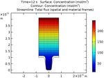
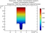
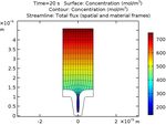
20 s of current density
operation, whichlines, and displacements
are shown in Figure 2. of the cathode and anode surfaces after 12, 14, 16,
and 20 s of operation, which are shown in Figure 2.Condens.
Condens.Matter 2018,4,3,26
Matter2019, x FOR PEER REVIEW 33 of
of 55
Figure2.2. Concentrations
Figure Concentrations ofof copper
copper ions (mol/m33), isopotential
ions(mol/m isopotential lines,
lines, current
current density
density lines,
lines, and
and
electrode
electrodedisplacement
displacementininthe
thecell
cellafter
after12,
12,14,
14,16,
16,and
and20
20s sofofwork.
work.
Lines
Linesofoflayer
layerthickness
thicknessshow
showthe thedevelopment
development ofof
non-uniform
non-uniform deposition
deposition of aofcopper
a copperlayer duedue
layer to
the non-uniform distribution of current density from the bottom to the upper edge
to the non-uniform distribution of current density from the bottom to the upper edge of the groove.of the groove. This
effect
This is directly
effect related related
is directly to the decrease in the concentration
to the decrease of copper of
in the concentration ions in the ions
copper depthinofthe
thedepth
cavity.of
From this, it can be concluded that with an increase in the duration of the process, the groove hole
the cavity.
on theFrom
upper edge
this, begins
it can to taper, and
be concluded its with
that overgrowth is possible
an increase in the due to theofnon-uniform
duration the process, deposition
the groove
thickness.
hole on the Therefore, for copper
upper edge beginsdeposition, the optimal
to taper, and process duration
its overgrowth is possibleis 14
dues. to the non-uniform
An analogical
deposition thickness.modeling
Therefore,was performed
for copper for thethe
deposition, silver deposition
optimal on the surface
process duration is 14 s. of the
trapezoidal profile.
An analogical modeling was performed for the silver deposition on the surface of the
Figure 3profile.
trapezoidal shows the distribution of the concentration of silver ions, isopotential lines, current
densityFigure 3 and
lines, shows thethe
displacement
distribution ofof the
the cathode and anode
concentration surface
of silver ions,after 12, 14, 16,
isopotential and
lines, 20 s
current
of operation.
density lines, and the displacement of the cathode and anode surface after 12, 14, 16, and 20 s
of operation.Condens.
Condens.Matter 2018,4,3,26x FOR PEER REVIEW
Matter2019, 4 of
of5 5
(a) (b)
(c) (d)
Figure 3. Concentrations of silver ions (mol/m3 ), isopotential lines, current density lines, and electrode
Figure 3. Concentrations
displacement in the cell afterof
12,silver
14, 16,ions (mol/m
and 20
3), isopotential lines, current density lines, and
s of operation.
electrode displacement in the cell after 12, 14, 16, and 20 s of operation.
It can be concluded that with an increase in the duration of the process, the cavity hole begins to
narrow It can be concluded
gradually due to that with an increase
the non-uniform in the duration
thickness of the process,
of the deposited the differs
layer, but cavity hole begins to
significantly
narrow gradually due to the non-uniform thickness of the deposited layer,
compared to the results for copper. The process of narrowing is slower, which may be associated with but differs significantly
acompared
lower initial to concentration
the results forofcopper.
silver. InThe
thisprocess
case, theofoptimal
narrowing is slower,
duration of the which may be associated
silver deposition process
with
is 20 s.a lower initial concentration of silver. In this case, the optimal duration of the silver deposition
process
Thus, is the
20 s.modeling of copper and silver deposition processes allows us to obtain preliminary
data onThus, the modeling
the formation of topology
of the copper and silver deposition
of contacts at the localprocesses allowson
metallization usthe
to obtain
surfacepreliminary
of printed
circuit boards and other electronics products, without resorting to full-scale experiments. of printed
data on the formation of the topology of contacts at the local metallization on the surface
circuit boards and other electronics products, without resorting to full-scale experiments.
4. Conclusion
4. Conclusion
The software COMSOL Multiphysics allowed us to perform the modeling of the processes of
copper Theandsoftware
silver electrodeposition
COMSOL Multiphysics in the trapezoidal
allowed us profile groove.the modeling of the processes of
to perform
Theand
copper results
silverobtained for the thicknesses
electrodeposition of the deposited
in the trapezoidal profilelayers of copper and silver can optimize
groove.
the deposition
The results regimes.
obtainedForforexample, it is advisable
the thicknesses of thetodeposited
carry outlayers
metal ofdeposition
copper and in a silver
periodic
can
mode,
optimizechanging the polarity
the deposition of the electrode
regimes. For example,to theitopposite. This should
is advisable to carryensure the alignment
out metal deposition of the
in a
concentration
periodic mode, of metal ions in
changing thethepolarity
depth ofofthe thegroove, and thus
electrode to thereduce the thickness
opposite. This shouldvariation of the
ensure the
layers on theofvertical
alignment walls.
the concentration of metal ions in the depth of the groove, and thus reduce the
thickness variation of the layers on the vertical walls.Condens. Matter 2019, 4, 26 5 of 5
Author Contributions: V.G.K. and L.V.K. provided the necessary theoretical materials, O.Y.E. performed
experiments and analyzed data.
Funding: This research received no external funding.
Conflicts of Interest: The authors declare no conflict of interest.
References
1. Tyulkova, A.A. Electrolytes for the electroplating of 3D micro-transitions. In Proceedings of the All-Russian
Scientific and Technical Conference, Moscow, Russia, 7–10 April 2015; Available online: http://studvesna.
ru/?go=articles&id=1270 (accessed on 28 September 2018).
2. Dzidziguri, E.; Ryzhonkov, D.I.; Levina, V.V. Nanomaterials Tutorial Nanomaterialy Uchebnoe Posobie; BINOM
Knowledge Laboratory: Moscow, Russia, 2010.
3. Belenky, M.A.; Ivanov, A.F. Electrodeposition of Metallic Coatings; Metallurgy: Moscow, Russia, 1985; p. 288.
4. The COMSOL® Software Product Suite. Available online: https://www.comsol.com/products (accessed on
17 September 2018).
© 2019 by the authors. Licensee MDPI, Basel, Switzerland. This article is an open access
article distributed under the terms and conditions of the Creative Commons Attribution
(CC BY) license (http://creativecommons.org/licenses/by/4.0/).You can also read


