MISSION DESIGN FOR THE TITAN SATURN SYSTEM MISSION CONCEPT
←
→
Page content transcription
If your browser does not render page correctly, please read the page content below
AAS 09-356
MISSION DESIGN FOR THE TITAN SATURN
SYSTEM MISSION CONCEPT
Nathan Strange,* Thomas Spilker,* Damon Landau,*
Try Lam,* Daniel Lyons,* and Jose Guzman†
In 2008, NASA and ESA commissioned a study of an international flagship-
class mission to Titan, Saturn, and Enceladus consisting of a NASA orbiter and
two ESA in situ elements, a montgolfière hot air balloon and a lake lander.
This paper provides an overview of the trajectory design for this mission,
which consists of a solar electric interplanetary trajectory to Saturn, a gravity-
assist tour of Titan and Enceladus, delivery of the two in situ elements, Titan
aerobraking, and a Titan circular orbit.
INTRODUCTION
In 2008, following from NASA’s 2007 Outer Planet Flagship Mission studies and ESA’s 2007
Cosmic Vision proposals (TandEM and Laplace), NASA and ESA commissioned joint studies of
both a Titan Saturn System Mission (TSSM)1-2 and a Europa Jupiter System Mission (EJSM)3-4 .
As a result of those studies and independent review, NASA and ESA prioritized EJSM for launch
in 2020 (consisting of a NASA Europa orbiter and an ESA Ganymede orbiter) with TSSM to
follow.
Per the study ground rules for the
joint 2008 NASA-ESA study, TSSM
was directed to investigate Titan as its
primary target but to also include
Enceladus and the Saturn System as
Level 1 requirements. The ground rules
also specified that NASA would
provide the orbiter and ESA would
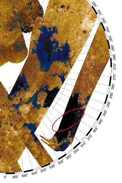
provide in situ elements. Figure 1
shows the complete TSSM flight
system concept that includes a NASA-
provided orbiter/SEP stage and two
ESA-provided in situ elements
(montgolfière hot air balloon and lake
lander). The purpose of the paper is to
describe the robust mission design that Figure 1. TSSM Flight System
responds to the ground rules and (conceptual design)
achieves all stated objectives.
*
Jet Propulsion Laboratory / California Institute of Technology, 4800 Oak Grove Drive, Pasadena, CA, 91109
†
Applied Physics Laboratory / John Hopkins University, 11100 Johns Hopkins Road, Laurel, MD, 20723
1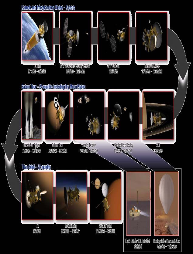
Table 1. Mission phase definition and description
     Phase                                                            Activity                                                Duration
                   Launch and Early Operations: Launch from CCAFS and activities, including initial acquisition by the
                   DSN, checkout and deployment of all critical spacecraft systems and preparations to begin thrusting        2 months
 Interplanetary    with the Ion Propulsion System (IPS).
     Cruise        Solar-Electric Cruise: Thrusting with the IPS and gravity-assist flybys of Earth and Venus. Several
                                                                                                                              5.0 years
    (9 years)      activities associated with flybys, thrust arc design, and Earth avoidance.
                   Ballistic Cruise: Once the SEP stage is jettisoned, the spacecraft enters a period of low activity.        3.3 years
                   Saturn Approach: Preparations and readiness testing for Saturn Orbit Insertion (SOI). Optical
                                                                                                                              6 months
                   navigation for upcoming Enceladus flybys.
                   Saturn Arrival: SOI performed between Cassini-like ring plane crossing in the F–G gap
                   ISE Delivery: Starts with 214 d period orbit with a Balloon Targeting Maneuver (BTM) to target to the
                   montgolfière entry position and velocity, release of the montgolfière, and a Periapsis Raise Maneuver
                   (PRM) to target the first Titan flyby. On the following orbit, a Lander Targeting Maneuver (LTM), Lander
  Saturn Tour
                   Release, and Orbiter Deflection Maneuver (ODM) deliver the Lander to Kraken Mare.
   (2 years)                                                                                                                   2 years
                   Enceladus Flybys: Seven close (100–500 km) flybys of Enceladus allowing in situ measurements of
                   the plume and remote sensing of active region. Additional opportunistic flybys of other icy moons
                   possible, such as Rhea in the example tour.
                   Final Energy Reduction: Series of orbits with large maneuvers to lower Titan V∞ to ~940 m/s prior to
                   Titan orbit insertion. Moderate-sized maneuver sets up proper initial orbit plane geometry.
                   Aerobraking: Starting from an 720 km by 15,000 km orbit, Titan aerobraking is used to help circularize
                                                                                                                              2 months
   Titan Orbit     orbit and provide deep sampling of Titan atmosphere to 600 km.
    (1.9 year)     Circular Orbit: Detailed surface mapping of Titan from a 1500 km, circular, polar (85°) orbit that starts
                                                                                                                             20 months
                   with and a decending node at 11:30 am LST and reaches 9:00 am by the end of the mission.
                   At end of prime mission, a ~15 m/s maneuver places spacecraft in an orbit that will decay in < 6
Decommissioning
                   months. During this phase small maneuvers will be used to keep the final entry point away from any         6 months
  and Disposal
                   regions of concern for planetary protection.
                   Minimal orbit maintenance requirements mean that the spacecraft could continue in Titan orbit for an extended
Extended Mission
                   mission of several years as allowed by funding and spacecraft health.

                                           Figure 2. TSSM mission timeline

                                                                2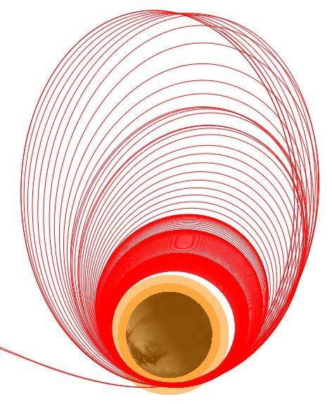
This paper will focus primarily on the mission design for the NASA orbiter. Both NASA and
ESA have publically available reports1-4 that give details on science objectives and flight system
design for the NASA and ESA flight elements, as well as the mission design for the ESA in situ
elements.
   Figure 2 is a graphical timeline showing the various phases of the TSSM mission that will be
discussed in the following sections. Table 1 gives the mission phase names with a description of
the activities that take place in each phase.
TSSM MISSION DESIGN
Overview
   For the TSSM baseline design, the NASA orbiter with both of the ESA provided in situ
elements would be launched together in September 2020 on an Atlas V 551 from Cape Canaveral.
The flight system would then perform a nine-year interplanetary trajectory with solar electric
propulsion in combination with gravity-assists of Venus and Earth to reach Saturn in October
2029.
   After a 746 m/s Saturn Orbit Insertion (SOI), the orbiter would begin a two-year Saturn Tour
Phase with 16 Titan and 7 Enceladus flybys. An ESA-provided RPS-powered montgolfière would
be delivered on the first Titan flyby, and an ESA-provided battery-powered lander would be
delivered on the second Titan flyby.
   After the two-year Saturn tour, the orbiter would enter Titan orbit with a 388 m/s Titan Orbit
Insertion (TOI) maneuver on September 29, 2031. The 22-month Titan Orbit Phase would begin
with a 2-month Aerobraking Phase. Over these 2 months, the apoapsis altitude would be reduced
from 15,000 km to 1500 km via Titan aerobraking passes. The orbit would then be circularized to
a 1500 km, near-polar (85°) mapping orbit. This orbit begins with a descending node at a Local
Solar Time (LST) of 11:30 am, which progresses to 9:00 am by the end of the 20-month Circular
Orbit Phase.
   At the end of the mission, a small de-orbit           Table 2. 21-day launch period for 2020
burn would place the spacecraft on an orbit                           opportunity.
that would decay and impact Titan by the end                         Beginning of       Middle of       End of
of the 6-month Decommissioning and                                     Launch            Launch         Launch
Disposal Phase. This decaying orbit would be                           Period            Period         Period
controlled and the final impact point of the          Date             Sep 10            Sep 19         Sep 30
                                                      C3 (km2/s2)        0.60              0.64           0.64
spacecraft can be deflected away from
                                                      DLA (deg)         -19.5°            -20.5°         -21.2°
regions several hundred kilometers across.            Launch             6265              6265           6265
This would enable the mission to avoid any            Mass (kg)
regions of planetary protection concern               SEP ∆V              2.63            2.68              2.77
where the possibility of near-surface water           (km/s)
                                                      Xenon Fuel          390              397              410
may have been identified during the mission.          (kg)

Launch
    The spacecraft would begin its journey on                  Table 3. Interplanetary events.
an Atlas V 551 rocket launched from Cape                         Event                   Date / Altitude
Canaveral. Table 2 details the prime launch              Launch                  Sep 10–30, 2020
opportunity     in   2020      (the    backup            Start SEP Thrusting     Dec 1, 2020
opportunities are detailed in a later section).          Earth-1                 Oct 27, 2021 / 16,900 km
                                                         Venus                   Feb 4, 2022 / 5300 km
Because TSSM uses Solar Electric                         Earth-2                 Jun 11, 2023 / 4500 km
Propulsion (SEP) to reach Saturn, there is               Earth-3                 Jun 11, 2025 / 600 km
virtually no change in performance over the              End SEP Thrusting       Oct 14, 2025
                                                         SOI                     Oct 28, 2029

                                                  3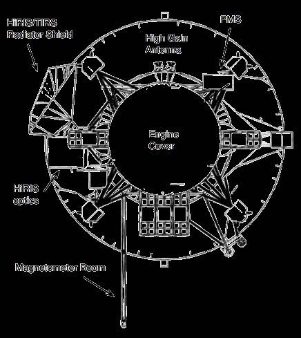
21-day launch period required by the study
ground-rules. The launch C3 doesn’t
change enough to get different launch
masses from the KSC ELV performance
website,5 hence the identical launch
masses. Moreover, the use of SEP would
enable the launch period to be extended
well beyond the 21 days shown for no
additional mass penalty.
Interplanetary Trajectory
    Figure 2 shows the SEP trajectory used
to reach Saturn. Table 3 details the flybys
and other major events during the
interplanetary cruise from launch to Saturn
arrival. The SEP thrusting and gravity-
assist flybys occur during the solar electric
cruise, which lasts for 5 years after launch.
At the end of the SEP thrusting, the SEP            Figure 2. 2020 EVEE SEP trajectory with
stage will be released such that it will            arrows showing thrust periods and directions.

impact Saturn (in order to alleviate
planetary protection concerns). Following                Table 4. SEP trajectory constraints.
the SEP thrusting, the next 3.3 years is a             Parameter     Value                 Rationale
ballistic cruise with no flybys. Six months         Flight-System     5%      Arrays are sized to provide 15kW after
                                                    Power Margin              accounting for a 5% margin on total
prior to Saturn arrival, activity increases to                                system power
prepare for SOI and to begin taking optical         Trajectory         5%     Reduced power protects against
                                                    Power Margin              heliocentric range variations across
navigation images to support the tour’s                                       operational contingencies
Enceladus flybys.                                   Propellant        10%     Provides robustness to engine
                                                    Margin                    performance changes
   Table 4 lists the design assumptions             Planned Thrust
                                                                 3%    Period of planned thrust arcs lost to
used for the low-thrust trajectory design.          Outages            downtime for spacecraft maintenance
These assumptions are intended to give                                 tasks, solar conjunction, etc.
                                               Unplanned         5%    Robustness to unplanned thrust
margin to the design and allow for future      Thrust Outages          outages
design refinements such as robustness to       Forced Coast     60 d   Two months for initial checkout of
periods     of     missed      thrust     and  after Launch            spacecraft and Ion Propulsion System
                                                                       (IPS)
implementation of targeting strategies for
                                               Coast during    +/- 1 d Coast period to avoid any problems
the Earth flybys. The values in this table     Flybys                  with solar eclipse and for thermal
result from a study conducted at JPL of                                control during Venus flyby
appropriate margins for SEP missions. A  6     Minimum   Flyby 400 km  Assumes a minimum operational
                                               Altitude                Earth flyby altitude of 300 km (based
principal difference in Table 4 from the                               on Galileo studies) with 33% margin
recommendations of the JPL SEP margins                                 for robustness to missed thrust.
study is shorter forced coast periods around
flybys and the use of 3% for planned thrust outages as opposed to the 5% recommended by the
study. This is because TSSM does not have planned thrust outages for radiometric tracking or
long tracking periods around flybys. This is possible because the flight system design can
accommodate radiometric tracking during thrust periods as a result of the articulating high gain
antenna and accelerometers (10 nano-g) sensitive to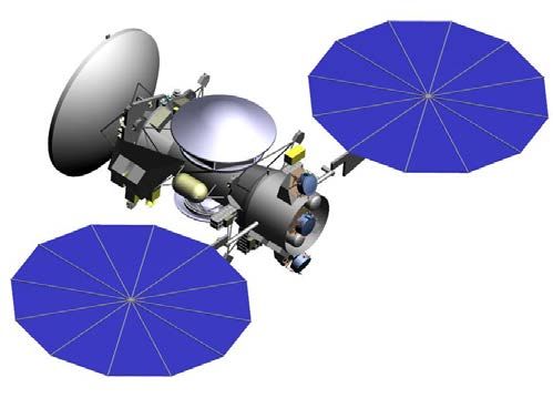
reduces the launch C3 needed from 11–19 km2/s2 for chemical in the 2018–2022 launch years to
only 0.6–1.4 km2/s2.
   For the types of SEP trajectories examined in the past, the mass of the SEP stage (778 kg,
including margin) offset much or all of this mass advantage. However, this study has developed
and applied powerful new methods for finding SEP trajectories that make use of inner solar
system gravity assists to provide superior performance.7
      This design currently uses three high performance NEXT ion engines (up to two thrusting
with one as a spare) and UltraFlex solar arrays that provide 15 kW of power at 1 AU. The TSSM
report1 details alternate trajectory options using other electric propulsion systems as well as
chemical propulsion trajectory options.
Saturn Tour Trajectory
   This phase begins with Saturn Orbit
Insertion (SOI). On either side of SOI,
the spacecraft crosses through the same
gap between the F and G rings used by
Cassini. During these crossings, like
Cassini, the High Gain Antenna (HGA)
would be put in the ram direction and
used as a dust shield. Cassini has given
us a much better understanding of the
debris environment near the rings and
TSSM could pass closer to the F-ring
than Cassini did. This saves propellant
and gives opportunities for spectacular
observations of the rings. In addition,    Figure 3. Planned Saturn Tour Phase showing
Cassini’s observations of the D-ring have        orbits numbered from SOI to TOI.
opened up an exciting possibility of a
passage between the D-ring and Saturn that would be examined during Phase A for possible
additional ∆V savings. The entire SOI burn would be visible to Earth and can be monitored via
the spacecraft’s low gain antenna (LGA).
    The 2-year gravity-assist tour is required to deliver the montgolfière and lander, provide flybys
of Enceladus with in situ sampling of its plume, and to reduce the orbiter energy prior to TOI for
efficient capture at Titan. This tour is designed to the constraints given in Table 5. The minimum
flyby altitude given in this table is a function of flyby v-infinity due to atmospheric heating. For
the Aerobraking Phase, the spacecraft is designed to tolerate atmospheric heating of up to 0.25
W/cm2. Table 6 gives the flyby altitudes where that heating is achieved using the atmospheric
models developed for the TSSM study.1 The minimum altitudes in Table 5 are above these values
to give additional margin for navigation performance.
    A two-year tour is detailed in Table 7 and depicted in Figure 3. This tour is part of a fully
integrated, end-to-end trajectory from launch to spacecraft disposal used to confirm the feasibility
of the TSSM mission design and to generate an accurate ∆V budget. It is point-design
representative of a much larger space of possible tours. After a decision to start the TSSM project,
starting in Phase A and continuing through Phase E, a tour design effort would be undertaken to
optimize the TSSM tour for Science to the level of the Cassini extended mission design. It is
reasonable to expect that such an effort will lead to significant improvement over what is already
an exciting tour design.

                                                 5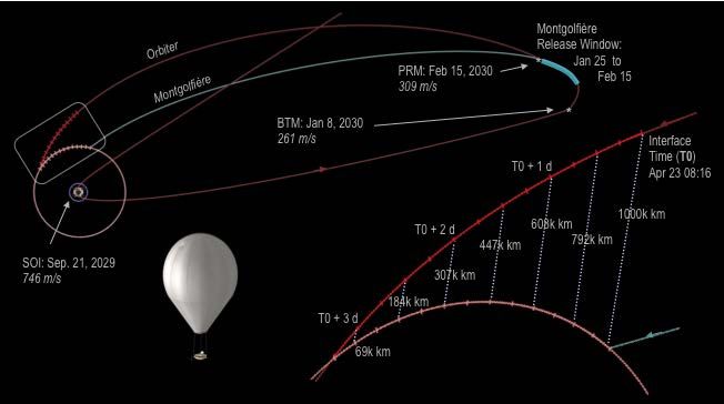
Table 5. Tour design constraints                                             Table 6. Titan flyby heating limits
  Parameter           Value                 Description                         Flyby V-Infinity               0.25 W/cm2 Heating Altitude
Duration               2 yr       Duration balances Saturn tour                     3 km/s                              720 km
                                  science with Titan orbit science.                 2 km/s                              680 km
Enceladus               4+        Must achieve at least 4 close                     1 km/s                              650 km
Flybys                            flybys over Enceladus South
                                  pole.
Minimum Titan         800 km      Accounts for spacecraft heating
Altitude for Vinf                 limits with margin for                    Table 7. Saturn tour design showing flyby
< 3 km/s                          navigational accuracy. First low          altitude and v-infinity along with post-flyby
                                  Titan flyby is limited to 900 km to       Saturn orbit inclination and period
                                  confirm atmospheric model.
Minimum Titan         750 km      Accounts for spacecraft heating                                                 Alt     Vinf    Per        Inc
                                  limits with margin for                              Body           Date        [km]    [km/s]    [d]       [deg]
Alttitue for Vinf
< 2 km/s                          navigational accuracy.                     SOI     Saturn        28-Oct-29     11236    6.6     214.0       5.7
Minimum Titan         720 km      Accounts for spacecraft heating            Ti1      Titan        26-Apr-30      1000    2.8      91.3      17.2
Altitude for Vinf                 limits with margin for
                                  navigational accuracy.                     Ti2      Titan        29-Jun-30      1200    2.7      45.6      24.1
< 1 km/s
Minimum               100 km      Leaves margin for navigational             Ti3      Titan        31-Jul-30       900    2.7      22.9      26.6
Enceladus                         uncertainty. This may likely be            Ti4      Titan        16-Aug-30      1077    2.7      22.9      19.3
Flyby Altitude                    lowered to 50 km or even 25 km
                                  after more detailed analysis.              Ti5      Titan        1-Sep-30        800    2.7      22.8       5.3
Minimum time            8d        Close flybys must be separated             Ti6      Titan        17-Sep-30      2331    2.7      15.1       0.6
between low                       by at least 8 days to allow
                                  sufficient time for maneuvers.             Rh1      Rhea         5-Oct-30       1273    3.6      15.5       0.5
altitude flybys
                                  Distant flybys may be closer if            Ti7      Titan        18-Oct-30      1817    2.8      11.4       0.5
                                  targeted as a Cassini-style
                                  double flyby.                              Ti8      Titan        3-Nov-30       1241    2.8      10.0       0.5
Solar                 Avoid       Tour maneuvers and flybys                  En1    Enceladus      7-Nov-30       1000    7.1       9.8       0.5
Conjunction         Conjunction   placed with consideration of Ka-
                                  band limits of > 3° SEP for                En2    Enceladus      14-Nov-30       100    7.1       9.8       0.5
                                  commanding and telemetry, and              En3    Enceladus      21-Nov-30       100    7.2       9.8       0.5
                                  > 7° SEP for radiometric
                                  tracking.                                  En4    Enceladus      28-Nov-30       307    7.1       9.8       0.5
                                                                             En5    Enceladus      5-Dec-30        100    7.1       9.8       0.5
                                                                             En6    Enceladus      11-Dec-30       100    7.1       9.8       0.5
                                                                             En7    Enceladus      18-Dec-30      1110    7.2       9.8       0.5
                                                                             Ti9      Titan        21-Dec-30      2128    2.8      11.4       4.8
                                                                             Ti10     Titan        6-Jan-31       2687    2.8      15.2       4.8
                                                                             Ti11     Titan        7-Feb-31       3460    2.8      22.9       3.8
                                                                             Ti12     Titan        23-Feb-31      2717    2.8      45.7       1.5
                                                                             Ti13     Titan        27-Mar-31      3477    2.8     133.9       0.5
                                                                             Ti14     Titan        29-Jun-31       750    1.7      43.4       0.3
                                                                             Ti15     Titan        28-Jul-31       720    0.96     22.9       5.1
                                                                             Ti16     Titan        13-Aug-31      2570    0.95     17.2       7.9
                                                                             TOI      Titan        29-Sep-31       760    0.94

                                                                                    Table 8. Distant flybys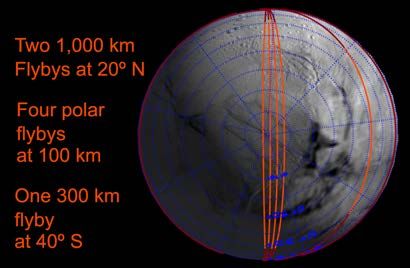
Figure 5. Montgolfière Delivery

  Figure 6. Lander Delivery

              7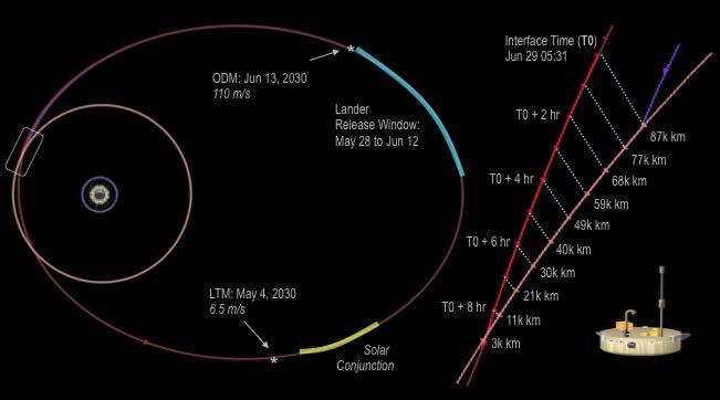
A primary focus of the Saturn tour
design is the Enceladus flybys, which are
optimized to make best use of TSSM
instrumentation that is greatly enhanced
relative to that carried by Cassini. These
flybys currently target the active region at
the Enceladus south pole (see Figure 4).
However, it is possible to retarget these
encounters in-flight if the active region
changes at the time of the TSSM mission.
Such a change in activity could be
determined from distant observation of
Enceladus prior to the close flyby phase.
   Although Enceladus is a key driver of
the tour design, the rich cadre of icy moons
at Saturn will provide many fortuitous
opportunities for science. In addition to the
close Rhea flyby shown in Table 7, there
are several other distant flybys of the icy
moons shown in Table 8. These flybys
provide many targets of opportunity that
add to the TSSM tour science beyond the
focus on Titan and Enceladus used for the
tour design.
Delivery of In Situ Elements
   Two in situ elements2 provided by ESA
are carried on the orbiter and released at
the beginning of the tour. After SOI, a                  Figure 7. Kraken Mare landing site.
Balloon Targeting Maneuver (BTM)

targets the montgolfière to 20°N, where              Table 9. In situ element entry parameters.
winds are thought to be strong enough at                       Parameter                        Value
the montgolfière’s 10 km altitude to                Montgolfière Destination         20° N at steady state
                                                    Montgolfière Interface Altitude  2000 km
maximize the likelihood of at least one             Montgolfière Entry Speed         6.3 km/s
circumnavigation of Titan. After BTM,               Montgolfière Entry Ang. Corridor 65° +/- 3° (3-sigma)
there is a three-week period from January           Mont. Release Vel. Uncertainty   35 mm/s (1-sigma)
                                                    Lander Landing Site              72°N 310°W, Kraken Mare
16, 2030 to February 6 during which the             Lander 3-σ Landing Footprint     600 km E-W X 160 km N-S
montgolfière can be released. Following             Lander Interface Altitude        2000 km
release, on February 7, the orbiter performs        Lander Entry Speed               3 km/s
                                                    Lander Entry Angle Corridor      65° +/- 1.5° (3-sigma)
a Periapsis Raise Maneuver (PRM) to                 Lander Release Vel. Uncertainty  35 mm/s 1-sigma
lower its Titan V-infinity to 2.8 km/s for
the upcoming Enceladus flybys. On the
next orbit, the lander is released (also with a 21-day window) prior to the second Titan flyby and
targeted to Kraken Mare, a hydrocarbon sea in Titan’s arctic region. Figures 5 and 6 detail the
timeline for release and arrival of the in situ elements.
   The montgolfière would arrive at Titan in daylight, in the morning, and has ~6 Earth days until
Titan nightfall. For the lander, its landing site in Kraken Mare is above Titan’s arctic circle and
does not get sunlight at the time of the mission due to Northern winter. Therefore, the lander is
designed with a lamp for illumination of its immediate vicinity (to look for possible material

                                                     8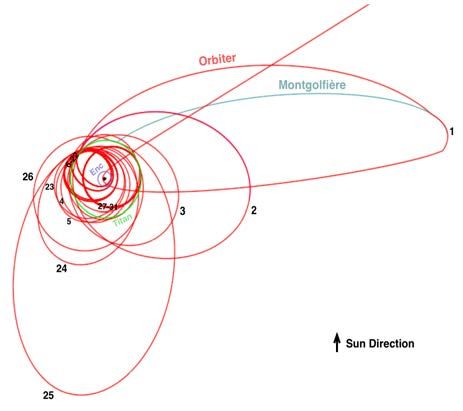
floating on the surface of Kracken Mare) and does not require daylight. Kraken Mare would be a
vast featureless expanse of open Sea at the landing site and little information is expected to be
gained from imaging beyond the immediate vicinity. When the lander arrives, the Sun is ~22°
below the horizon, but a gibbous Saturn is visible and provides 2.5 times the light of a full moon
at Earth. An alternate delivery of the Lander is also possible which would arrive in twilight when
the Sun is only ~8° below the horizon and Saturn is in a crescent phase providing roughly the
illumination of one full moon.
    The delivery of both elements is operationally robust in offering three-week windows for the
releases. Should this robustness not be sufficient, contingency tours could be developed (as were
developed for Cassini-Huygens) that would enable either element to be delivered on a subsequent
Titan flyby. Such contingencies would insert an additional orbit in the tour and shift the orbiter’s
TOI 6–8 months later for a montgolfière contingency and 2–4 months later for a lander
contingency. Such contingencies could be developed during the project’s operational phase when
the tour design is finalized if the project determines that the three-week windows in the current
design are not sufficiently robust.
   Table 9 details the delivery targets for the in situ elements along with the delivery dispersions.
This table also gives the landing ellipse. Figure 7 shows the landing ellipse for the lander on a
polar plot of Kraken Mare.
    A covariance study was done for another case with release of the montgolfière and lander
several months prior to SOI (an earlier iteration of the TSSM design). This study found that the
principal sources of error at the 2000 km interface were: 1) time from release to entry, 2) errors
introduced by the separation mechanism, and 3) radiation pressure from any RPS on the in situ
element. Moreover, it was found that this error at the interface altitude was a small factor in
determining the size of the landing ellipse compared to errors introduced by winds during
descent. A good approximation of the relative effects of these two error sources is that the
delivery errors at the interface lead to the smaller North-South axis of the landing ellipse, and that
wind induced errors lead to the larger East-West axis. To decrease the North-South axis would
require reducing delivery errors (e.g., by reducing the time from release to entry) and to decrease
the East-West axis would require reducing the effect of the winds (e.g., by reducing the descent
time with a smaller parachute).
    The constraints in Table 9 arose from this study, which showed that velocity uncertainties on
the order of 20–25 mm/s on the in situ elements after release were achievable with a Cassini-
Huygens like delivery scheme. The entry angle constraints and delivery dispersions at the
interface reflected in Table 9 are possible with velocity uncertainties of ~35 mm/s at release.
In Situ Element Relay
    The montgolfière would be a long-lived vehicle with a radioisotope power source. During its
nominal six month mission the primary relay for the montgolfière is through the TSSM orbiter,
although limited direct to Earth (DTE) communication is also possible. The relay will occur
during some Titan flybys and while the orbiter is in Saturn orbit. This would allow a total data
transfer of >1.3 Tb.
   The lander would be a short-lived battery powered probe with a nominal three-hour surface
mission and a six-hour descent. Its only relay would be to the TSSM orbiter, which will provide a
dedicated nine-hour relay period during the second Titan flyby with a capability of 3.4 Gb of
data.
   The critical events of entry, descent, and landing (EDL) for the lander and the entry, descent,
and inflation (EDI) for the montgolfière would be visible for radio monitoring via relay with the

                                                  9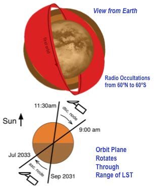
orbiter. The montgolfière’s EDI could also be monitored from Earth, but that is not required.
Figures 5 and 6 depict the relay geometry for both elements during these periods.
    The relay from the orbiter to both elements is X-band through the High Gain Antenna (HGA).
When the orbiter is > ~500,000 km in range the HGA beam width is sufficient to cover the entire
visible hemisphere of Titan. However, when the range is sufficiently close, the footprint from the
HGA is smaller than the a priori knowledge of either in situ element’s location. For the lander,
this would occur when the range is < ~30,000 km. The montgolfière would be a mobile platform
that must be located prior to every flyby with telecom relay.
    To maintain the link in these situations, the orbiter would maintain and update an on-board
estimate of the location of each in situ element during the relay. This is done by periodically
performing a two-axis peak scan with the HGA to locate each in situ element within the HGA
footprint. For the lander, this will enable the link to be maintained to the minimum range of
~3,000 km at the end of the 9 hr relay period. For the montgolfière, this would enable the link to
be maintained through close Titan flybys.
   The montgolfière would have the ability to detect the orbiter’s transmitted signal and turn its
own 0.5 m HGA in the direction of the orbiter to maximize communication rates without complex
(given the lack of guide-stars) on-board attitude determination.
   Finally, there would be periods of ~8 days in duration when the montgolfière is not in
communication with the orbiter due to occultation by Titan. The winds at the 10 km altitude at
which the montgolfière is designed to float, would move the montgolfière along lines of relatively
constant latitude. This allows for coarse interpolation of its position through these periods to
predict windows when the montgolfière would reemerge into the orbiter’s view. In general, the
orbiter would be far enough away that the HGA will cover all of Titan when the montgolfière
reemerges. Once the link is established, a peak scan could then be used to get a fix on the
montgolfière’s location.
    An additional science requirement on the montgolfière is to reconstruct its location to 1 km
knowledge accuracy in latitude and longitude for the interpretation of measurements taken by the
montgolfière. Angular data from the orbiter’s peak scan and the pointing of the montgolfière’s
HGA would help in this determination, but it will primarily be done via radiometric tracking
employing range data and two-way Doppler from the orbiter. Post-processing correlation of the
time-stamped images from the montgolfière to global Titan maps, created by TSSM in the
Circular Orbit Phase, would provide even more precise knowledge of the montgolfière’s position
for science data analysis. This terrain-based optical navigation would also provide a way to
estimate the montgolfière’s position during periods when it is not in view.
Titan Aerobraking
    Titan Orbit Insertion (TOI) places the orbiter into a 15,000 km by 720 km 85° inclination
elliptical orbit around Titan. Over several orbits, Saturn’s gravitational perturbations then raise
periapsis of this orbit before pushing it lower into the atmosphere. During these atmospheric
passes, drag lowers the orbit apoapsis (See Figure 8). As the periapsis altitude nears 600 km, the
heating on the spacecraft reaches a peak heating of 0.23 W/cm2, which is below the aerobraking
trajectory heating threshold of 0.25 W/cm2. This value was chosen to be roughly half of the
aerobraking heating limits from other missions shown in Table 10. Before the trajectory heating
threshold would be reached, a maneuver is performed to raise periapsis. This maneuver is sized
such that Saturn’s gravity will subsequently lower the periapsis back into Titan’s atmosphere.
    This phase enables many low altitude passes for in situ sampling of Titan’s atmosphere as well
as in situ measurement of Titan’s intrinsic magnetic field below the ionosphere. Figure 9 details
the altitude versus latitude coverage during this phase showing complete coverage of the southern

                                                10
hemisphere below 1000 km altitude. Additionally, the high apoapses at the beginning of this
phase enable global monitoring of Titan for clouds and other features of the troposphere and
excellent geometry for Titan limb sounding.
The aerobraking sequence is designed using an atmospheric model developed for the study by
experts on Titan’s atmosphere using Cassini and Huygens data. This model will be updated based
on Cassini extended and extended-extended mission data prior. In addition, several low-altitude
flybys during the tour shown in Table 7 provide an opportunity to directly measure the
atmosphere prior to the start of aerobraking so as to confirm the Titan atmospheric models early
enough to allow for adjustments to the aerobraking trajectory.
Titan’s atmosphere is more stable than Mars’ with a predicted 1-sigma density variation of
15% pass-to-pass compared to 30% 1-sigma for Mars. In addition, a hazard to Mars aerobraking
is planet-wide dust storms that can pop up over a span of a few days and increase density by a
factor of 10. Titan does not experience anything similar to these planet-wide storms, and the
aerobraking operations are much more benign as a result.
In fact, atmospheric variability is a small effect in comparison to perturbations from Saturn’s
gravity that would raise and lower periapsis of the elliptical aerobraking orbit. Most of the 79 m/s
of maintenance ∆V during aerobraking is required to counteract Saturnian perturbations. If the
Aerobraking Phase were shortened to 30 days, Saturn’s effect is reduced and the maintenance ∆V
is reduced to only 63 m/s.
Attitude stability during aerobraking is maintained by placing the spacecraft in a passively
stable attitude shown in Figure 10, which has the large drag area of the High Gain Antenna
(HGA) behind the center of mass of the spacecraft like a shuttlecock. Prior to the start of
aerobraking, the HGA will be placed using the current estimate of the center of mass location so
as to minimize attitude transients about the stable attitude.
Figure 11 shows the portions of the spacecraft that would be exposed to the ram direction of
the flow during aerobraking. The majority of this area is the HGA and the engine cover. The PMS
(Polymer Mass Spectrometer) instrument has a sampling port that is aligned with the flow for
science data collection.
More information on the design of the TSSM aerobraking phase may be found in a paper by
Lyons and Strange.8
Titan Circular Orbit
After aerobraking, the orbiter enters a 1500 km circular orbit at an inclination of 85°. The
1500 km altitude was chosen because of the negligible drag at this altitude allows for long
spacecraft life, while still being at a reasonable distance from the surface. However, lower
altitudes are possible for reasonable amounts of orbit maintenance. As future work, this altitude
will be re-examined and fine-tuned for optimal total mission science return.
The 85° inclination was chosen because it is near-polar and allows coverage of almost all of
Titan’s surface. By being slightly off-polar, Saturn’s gravity will rotate the orbit plane. Saturn’s
orbit results in an apparent motion of the Sun in Titan’s sky of ~9°/year. By choosing 85° as
opposed to 95° inclination the orbit plane rotation will add to the Sun’s apparent motion leading
to a ~20°/yr motion of the Sun with respect to the orbit plane. This is a ~2.5 hr change in Local
Solar Time (LST) of the orbit’s descending and ascending nodes over the 20-month Titan
Circular Orbit Phase.
11Figure 10. Attitude during aerobraking
Table 10. Aerobraking Heating Limits
Heating Limit
Spacecraft (W/cm^2)
Comment
MRO 0.55 limit due to solar panels
MGS 0.79 limit due to solar panels
Figure 8. Aerobraking phase orbits.
s/c not designed for aerobraking;
Magellan 0.40 solar panels especially sensitive
Odyssey 0.65 limit due to solar panels
Figure 9. Aerobraking latitude coverage
Figure 12. Plane rotation during Titan
Figure 11. View from ram direction circular orbit phase
12The orbit plane starts with a descending node at a 11:30 am LST which rotates to 9:00 am by
end of mission (see Figure 12). This allows a range of Solar phase angles from low phase angles
that provide high signal to noise for optical remote sensing to higher phase observations that
provide greater shadowing to highlight relief. In addition, as shown in Figure 12, this plane
rotation allows Titan atmospheric radio occultations at a wide variety of latitudes.
Decommissioning and Disposal
After the end of the prime mission there would be a six-month Decommissioning and Disposal
Phase during which the spacecraft will impact Titan. At the end of the mission, a 15 m/s
maneuver lowers periapsis to ~1340 km altitude. Perturbations from Saturn’s gravity will
increase the eccentricity of this orbit over a period of 4–5 months until the periapsis decreases to
~1000 km and atmospheric drag accelerates the decay. From this point, the orbit will decay and
impact in about a week. Small maneuvers made before and during this final descent can move the
final impact point several hundred km on Titan’s surface. This enables the final impact to be
targeted away from any places, identified during the mission, where liquid water may be near the
surface (i.e. volcanically active areas) that would be of planetary protection concern.
Mission ΔV
Table 11 shows the mission chemical ∆V budget for both bi-prop and mono-prop along with
the associated rationale for each line item. The deterministic mission ∆V has been verified by
high fidelity modeling of the trajectory. The statistical ∆V is estimated, with rationales given in
the table, based on Cassini and Galileo historical experience.
The ∆V in this table is that needed to implement the baseline mission design along with
margin to cover values that were either estimated (e.g., statistical and mono-prop ∆V) or likely to
grow as the trajectory is better optimized for science. Maneuvers that will change little as the
mission design evolves need little margin (e.g., SOI, TOI, PRM). The tour ∆V, however, benefits
from the margins shown to enable flexibility in the upcoming refinement of the tour design.
Similarly, the aerobraking maintenance ∆V margin is to allow for flexibility in new maneuver
strategies to allow better optimization for spacecraft operations. Should changes to the mission
design as the project progresses require more ∆V than shown, the interplanetary SEP trajectory
can be modified to provide significantly more mass to Saturn (up to 340 kg more) for longer
flight times.1,7
Backup Launch Opportunities
The baseline mission launches in 2020 on a SEP EVEE trajectory. The primary backup launch
opportunity is a 2022 EVEE gravity assist trajectory detailed in Tables 12 and 13. The 2022
backup gives the maximum xenon load (550 kg after 10% margin is added) used for sizing the
SEP stage tanks.
The 2022 trajectory has a very similar chemical ∆V budget to the 2020 trajectory (see Table
11). The difference being in that SOI decreases to 689 m/s from 746 m/s. Another backup option
exists six months earlier in 2021, but it arrives at Saturn the same time as the 2022 trajectory.
Table 14 describes the features of other SEP trajectories in the 2018-2022 launch years such as
flight time and size of SOI. All of these trajectories are assumed to use the same orbiter and in
situ element designs, and the table shows they achieve similar mass capability for the orbiter as
the baseline trajectory with lower chemical propellant loads than the baseline (i.e. the propellant
would fit in the baseline tank design).Table 11. Mission ∆V budget.
Bi-Prop Mono-Prop
∆V [m/s] ∆V [m/s] Description
Interplanetary Several small maneuvers needed after SEP stage release for final Saturn
4 1
TCMs targeting. SEP stage is released prior to these maneuvers.
Saturn Orbit Insertion modeled as Finite Burn with gravity losses. Three trades
SOI 746 0 could reduce the size of SOI: 1. Longer flight time to Saturn, 2. Longer flight time
from SOI to first Titan flyby, 3. Moving ring plane crossing to gap below D-ring.
SOI Clean-Up estimated as 3% of SOI to represent a 3-sigma case. By estimating
SOI-CU (3%) 22 0 the largest maneuver’s cleanup as 3-sigma, TSSM is robust to at least one 3-sigma
cleanup.
Balloon Targeting Maneuver modeled to deliver montgolfière to Titan entry
BTM 261 0 target. Increasing the period of the initial Saturn orbit may reduce this ∆V. This
could be possible without increasing the total tour duration.
BTM Clean-Up ∆V in one or two maneuvers estimated as 2% of BTM to represent
BTM-CU (2%) 5 1 a 2-sigma case. Additional 1 m/s of mono-prop ∆V added for precision targeting.
The montgolfière is released after these maneuvers.
Periapsis Raise Maneuver to set-up first Titan flyby. Increasing the period of the
PRM 309 0 initial Saturn orbit may reduce this ∆V. This could be possible without increasing
the total tour duration.
PRM-CU (2%) 6 0 PRM Clean-Up estimated as 2% of PRM to represent a 2-sigma case.
LTM 7 0 Lander Targeting Maneuver modeled to deliver lander to Kraken Mare.
LTM Clean-Up estimated as 1 or 2 maneuvers totaling 1 m/s of mono-prop ∆V.
LTM-CU 0 1 Lander is released following these maneuvers.
Orbiter Delay Maneuver provides 9 hour delay from lander entry at Titan and
ODM 110 0 orbiter closest approach at the end of the lander relay.
ODM-CU (2%) 2 0 ODM Clean-Up estimated as 2% of ODM to represent a 2-sigma case.
Deterministic ∆V found from integrated tour trajectory. This ∆V is required primarily
Tour Deterministic 40 0 for targeting of Enceladus flybys. Otherwise, the tour would be nearly ballistic.
Tour Margin (50%) 20 0 This margin leaves rooms for future refinement of the tour design.
Leveraging Pump- ∆V to decrease Titan V-infinity prior to TOI. This ∆V may be reduced by adding 1–
197 0
Down 2 months to the tour duration.
∆V needed (in two maneuvers) to achieve the proper orientation of the Titan orbit
Beta Adjustment 25 0 with respect to the Sun (i.e., a descending node crossing at 11:30 am LST). This
∆V could be reduced with refinements to the tour design.
Estimate of the statistical ∆V needed for the entire tour phase extrapolated from
Tour Phase 12 12 the Cassini Extended Mission tour design experience. This estimate is 0.5 m/s of
Statistical bi-prop and 0.5 m/s of mono-prop per targeted flyby (24).
Titan Orbit Insertion modeled as Finite Burn with gravity losses. This ∆V could be
TOI 388 0 reduced with further refinement of the leveraging pump-down and of the
aerobraking phase.
TOI-CU (2%) 8 0 TOI Clean-Up estimated as 2% of TOI to represent a 2-sigma case.
∆V from simulated 2 month aerobraking design with drag and Saturn gravity. This
Aerobraking 79 0 ∆V can be reduced with a shorter Aerobraking Phase (e.g., 63 m/s for a 30 day
Maintenance aerobraking).
This margin is to maintain flexibility in the future design of the aerobraking
Aerobraking 12 0 maneuver strategy. However, aerobraking maintenance ∆V may also decrease
Margin (15%) with this refinement.
∆V required to raise periapsis and to circularize the orbit at the end of aerobraking.
Circularization 85 0 This ∆V would be reduced for a lower circular orbit. (to ~65 m/s for 1400 km or
~45 m/s for 1300 km)
Circular Orbit ∆V needed to maintain circular orbit from simulation with drag and Saturn gravity +
0 4
Maintenance 100% margin. This large margin is to maintain operational flexibility.
De-Orbit and 15 m/s for de-orbit plus additional ∆V margin to control the 6-month orbit decay.
18 2
Disposal
Total 2356 21Table 12. 21-day launch period (2022). Table 13. Interplanetary events (2022).
Middle of End of Event Date / Altitude
Beginning of Launch Launch Launch Mar 27–Apr 16
Launch Period Period Period Begin SEP Thrusting May 26, 2022
Date Mar 28, 2022 Apr 6 Apr 16 Earth-1 May 25, 2023 / 15770 km
C3 [km2/s2] 1.44 1.40 1.44 Venus Sep 19, 2023 / 5550 km
DLA [deg] 18.8° 20.4° 20.9° Earth-2 Jun 4, 2024 / 1550 km
Launch 6175 6175 6175 Earth-3 May 9, 2026 / 600 km
Mass [kg] End SEP Thrusting Aug 7, 2027
SEP ∆V 3.33 3.33 3.33 SOI (689 m/s) Sep 30, 2031
(km/s)
Xenon 500 500 500
Fuel (kg)
Table 14. SEP trajectories in alternate launch years.
FT to Launch Launch Xenon Saturn SOI Chem. Orbiter
Launch Arrival Saturn C3 Mass [kg] Fuel V∞ ∆V Fuel Mass
Path Date Date [y] [km2/s2] (A551) [kg] [km/s] [m/s] [kg] [kg]
EEVEE Jul 2018 Jan 2028 9.5 1.2 6200 500 6.20 680 2432 1705
EVEE Jan 2019 Feb 2028 9.0 1.2 6200 500 6.20 680 2432 1705
EVEE Sep 2020 Oct 2029 9.0 0.8 6240 445 6.66 745 2533 1703
EEVEE Oct 2021 Mar 2031 9.4 1.4 6175 500 6.10 670 2414 1704
EVEE Apr 2022 Feb 2031 8.8 1.4 6175 500 6.10 670 2414 1704
Trajectory Modeling Assumptions
Prior to this study, it was widely assumed that a Titan mission with an orbiter and in situ
elements would require Titan aerocapture for the orbiter, especially with an Atlas V launch. This
study use v-infinity leveraging techniques9-10 to accomplish the TSSM objectives without
aerocapture. In order to verify the correctness of these new approaches and the associated ∆V
budget, the trajectory was integrated from launch to end of mission in a high fidelity force model
including n-body perturbations and Titan atmospheric drag when appropriate. Forces dependant
on the spacecraft design and attitude were neglected (e.g., solar radiation pressure, RPS radiation
pressure, etc), but these forces are not expected significantly to change the ∆V budget or the
correctness of the trajectory.
CONCLUSION
The TSSM mission design effort has resulted in an innovative end-to-end trajectory that
achieves all science objectives1 using techniques that have all been demonstrated on previous
planetary missions. Using an Atlas V (551) launch vehicle and the aid of a SEP stage, the TSSM
architecture is capable of delivering two in situ elements, a montgolfière hot air balloon (600 kg
allocation) and a lake lander (190 kg allocation) as well as a flagship-class orbiter (1613 kg dry
mass with 35% system margin) to Titan. The mission design also includes an innovative tour
through the Saturn system that captures Saturn and Enceladus level 1 requirements. As a result of
the 2008 TSSM study, it is clear that attractive solutions exist for a comprehensive mission to
both Titan and Enceladus. Future work will continue to explore such options.
ACKNOWLEDGEMENTS
The research described in this paper was carried out at the Jet Propulsion Laboratory,
California Institute of Technology and the Applied Physics Lab, Johns Hopkins University, under
a contract with the National Aeronautics and Space Administration. This work would not have
been possible without the close collaboration with the ESA Mission Analysis team at ESOC, andArnaud Boutonnet in particular. We would like to acknowledge the hard work completed by all of
the members of the international Joint Science Definition Team (JSDT) and the joint NASA/ESA
TSSM study team (The ESA study team included members from ESA/ESTEC, ESA/ESOC,
CNES, and Observatoire de Paris-Meudon. The NASA study team included members from
CalTech/JPL, JHU/APL, NASA/GRC, NASA/GSFC, and the University of Arizona.).
REFERENCES
1
“Titan Saturn System Mission Final Report on the NASA Contribution to a Joint Mission with ESA,” Jet
Propulsion Laboratory, January 30, 2009. See also: http://opfm.jpl.nasa.gov/library/
2
“TSSM In Situ Elements: ESA Contribution to the Titan Saturn System Mission,” ESA-SRE(2008)4,
February 12, 2009. See also: http://opfm.jpl.nasa.gov/library/
3
“Jupiter Europa Orbiter Mission Study 2008: Final Report,” Jet Propulsion Laboratory, January 30, 2009.
See also: http://opfm.jpl.nasa.gov/library/
4
“Jupiter Ganymede Orbiter: ESA Contribution to the Europa Jupiter System Mission,” ESA-SRE(2008)2,
February 12, 2009. See also: http://opfm.jpl.nasa.gov/library/
5
“NASA Launch Services Program Vehicle Performance Web Site,” http://elvperf.ksc.nasa.gov/
6
D.Y. Oh, D.F. Landau, T. Randolph, P. Timmerman, J. Chase, J.A. Sims, and T. Kowalkowski, “Analysis
of System Margins on Deep Space Missions Utilizing Solar Electric Propulsion,” presented at the 44th
AIAA/ASME/SAE/ASEE Joint Propulsion Conference & Exhibit 21 - 23 July 2008, Hartford, CT.
7
T. Lam, D.F. Landau, and N.J. Strange, “Broad Search Solar Electric Propulsion Trajectories to Saturn
with Gravity Assists,” AAA Paper 09-355, AAS/AIAA Astrodynamics Conference, Pittsburgh, PA, Aug.
2009.
8
D.T. Lyons and N.J. Strange, “ Aerobraking at Titan,” AAA Paper 09-358, AAS/AIAA Astrodynamics
Conference, Pittsburgh, PA, Aug. 2009.
9
J.A. Sims, J.M. Longuski, and A. Staugler, “V-Infinity Leveraging for Interplanetary Missions: Multiple-
Revolution Orbit Techniques,” Journal of Guidance, Control and Dynamics, Vol. 20, No. 3, 1997, pp.
409415.
10
N.J. Strange and J.A. Sims, “Methods for the Design of V-Infinity Leveraging Maneuvers,” AAS Paper
01-473, AAS/AIAA Astrodynamics Conference, Québec, Québec, July/Aug. 2001.You can also read