MARSZUG-A Space Train for Regular Delivery of Astronauts onto Mars
←
→
Page content transcription
If your browser does not render page correctly, please read the page content below
Advances in Aerospace Science and Technology, 2021, 6, 93-113
                                                                                              https://www.scirp.org/journal/aast
                                                                                                         ISSN Online: 2473-6724
                                                                                                           ISSN Print: 2473-6708

MARSZUG—A Space Train for Regular Delivery
of Astronauts onto Mars

Alexander Rubinraut

Design Office Expeditions to Planets (Expplanet), Munich, Germany

How to cite this paper: Rubinraut, A.         Abstract
(2021) MARSZUG—A Space Train for
Regular Delivery of Astronauts onto Mars.     A project of the space train MARSZUG intended for regular delivery of as-
Advances in Aerospace Science and Tech-
                                              tronauts to Mars is considered. In the first stage of the flight, the astronauts
nology, 6, 93-113.
https://doi.org/10.4236/aast.2021.62007       with the help of the carrier rocket equipped with a chemical rocket engine are
                                              delivered to the international space station (ISS). To deliver astronauts from
Received: February 18, 2021                   Earth’s orbit to Mars orbit, a space train design consisting of two rockets,
Accepted: June 1, 2021
Published: June 4, 2021
                                              which have superconductive magnetoplasma electric engine MARS, has been
                                              developed. For the first time, a combined propulsion system MARS-M has
Copyright © 2021 by author(s) and             been developed for the train movement, allowing carrying out the pitching,
Scientific Research Publishing Inc.
                                              yaw and rotation of the rocket. This greatly simplifies the rocket control sys-
This work is licensed under the Creative
Commons Attribution International             tem and increases its reliability. The energy source of the electric engines is a
License (CC BY 4.0).                          sliding solar panel made of gallium arsenide. Working substance to create
http://creativecommons.org/licenses/by/4.0/   reactive thrust of electrorocket engines—hydrogen is stored in a liquid state
                Open Access
                                              in the cryogenic tank located along the longitudinal axis of the rocket. In the
                                              nasal part of the front electric rocket, a shaft rotating in a superconductive
                                              bearing is located. The shaft has a cylindrical nozzle, on which with the help
                                              of docking units two takeoff-landing capsules TLC-1 and TLC-2 are installed
                                              with which help landing and takeoff from the surface of Mars is carried out.
                                              This allows astronauts to constantly stay during the flight under the influence
                                              of gravity. To refuel the space train with liquid hydrogen in the orbit of Mars,
                                              the design of a space refueler with a chemical rocket engine is developed. The
                                              developed space train is able to regularly deliver astronauts to the surface
                                              near the northern pole of Mars.

                                              Keywords
                                              Mars, MARS-K Combined Propulsion System MARS-K, Superconductive
                                              Magnetoplasma Electrorocket Engine, Takeoff-Landing Capsule, Space
                                              Refueler

DOI: 10.4236/aast.2021.62007 Jun. 4, 2021                        93                Advances in Aerospace Science and Technology
A. Rubinraut
1. Introduction
Exploration and mastering of Mars still remains a priority for astronomy and as-
tronautics.
It’s time for intensive exploration of Mars with the help of spacecrafts.
Currently, up to ten automatic interplanetary stations (AIS) are orbiting as ar-
tificial satellites around the planet Mars. There are two rovers operating on the
surface of Mars, to which another rover with a lifespan of 10 years is expected to
be added in 2021 [1].
In recent years, the most successful one was the flight of the “Phoenix” space-
craft, which has landed on the surface near the north pole of Mars in 2008 and
has got water from the Martian soil [2].
At the same time, an expedition to the surface of Mars still remains an unat-
tainable dream.
The reason for this is that today there is no spacecraft, in which a person can
reach the surface of Mars and safely return to the native Earth.
The creation of a technical device capable of delivering astronauts to Mars
must be admitted as the most important scientific and technological challenge
facing humanity.
Therefore, the development of a space train for the regular delivery of astro-
nauts to Mars is the subject of scientific and designer research carried out in this
work.
It should be recalled that today NASA continues its long-term work on the
creation of a spacecraft for astronauts’ flight to Mars. In 2017, a new program
was adopted, which provides for the creation of super-heavy rocket carriers SLS
with a payload capacity in the Earth’s orbit of 130 tons [3].
In the NASA project, the SLS spacecraft retains a traditional design that uses a
combination of chemical rockets operating on liquid and solid fuel using oxygen
as an oxidizer.
The program provides for implementation of the successive missions.
Mission 1 is an unmanned flight of the “Orion” capsule to the lunar surface
until 2020. Mission 2 is to be implemented with the help of the created block 1 in
2023. At the same time, the expedition of four astronauts should be landed on
the surface of the Moon.
Further plans of NASA are related to the development and creation of a space-
craft for the flight to Mars, whose propulsion device will be a bundle of chemical
rocket engines type RS-25.
The spacecraft should be placed in unit 2, in the head part of the SLS rocket. It
will be the most powerful rocket ever built.
The first launch of such a rocket is expected to carry out in 2045.
As a result, in the middle of the 21st century, finally, there will be created the
technical device capable of delivering to Mars that one astronaut can stay on the
surface for several days.
The estimated duration of the expedition from the time of take-off from the
DOI: 10.4236/aast.2021.62007 94 Advances in Aerospace Science and TechnologyA. Rubinraut
spaceport at Cape Kennedy to the splashdown of the Orion capsule in the Pacific
Ocean will be 540 days [3]. It should be noted that NASA’s SLS spacecraft does
not provide for the creation of artificial gravity in the cabin of astronauts during
interorbital flight. But such a long stay in weightlessness can have severe conse-
quences for the health of the crew members of the expedition.
Determining the cost of the expedition today is quite a complex task. But un-
doubtedly it will be the most expensive space-rocket complex ever created at
NASA. In order to get rid of these shortcomings and solve the problem of en-
suring the regular delivery of astronauts to the surface of Mars, the author de-
cided to go another alternative way, providing for the use of electric rocket en-
gines.
An analysis of NASA’s SLS spacecraft flight project has shown that the trajec-
tory of the flight towards Mars consists of three sections, at each of which the
gravitational field differs significantly in the value.
At the first section of the trajectory: the Earth’s surface and the Earth’s orbit,
the spacecraft overcomes the force of gravity of the Earth. In this section, chem-
ical rocket engines should be used.
At the second section of the trajectory: the orbit of the Earth and the orbit of
Mars the flight of the rocket spacecraft takes place in the conditions of
weightlessness. The use of chemical rocket engines in this case is irrational. Be-
cause the specific pulse of the chemical rocket engine is 400 seconds, while the
electric rocket engine has specific pulse of 8000 sec. To reduce the consumption
of the working substance during interorbital flight, electric rocket engines
should be installed on the spacecraft.
At the third section of the trajectory, when the spacecraft remains in orbit of
Mars, and the spacecraft, a takeoff-landing capsule with astronauts on board is
under the influence of the gravity of Mars, and a chemical rocket engine should
be used.
The design calculations have shown that in order to solve the problem of reg-
ular delivery of astronauts to the Mars surface with minimum flight time it is ad-
visable to divide the process into two stages.
In the first stage, a carrier rocket equipped with a chemical rocket engine will
deliver astronauts to the International Space Station. For this purpose, the project
uses the Atlas V carrier rocket with space capsule STS 100 Starliner developed by
Boing.
In the second stage, a space train should be developed with which help flights
between the Earth’s orbit and the orbit of Mars are carried out.
At the interorbital space train, the electric rocket engines and two takeoff-landing
capsules should be installed.
This will allow the performing movement of 10 astronauts from the ISS moo-
rage at the Earth orbit, to land on the surface of Mars, to take off from the sur-
face of Mars and to carry out return flight from Mars orbit to the ISS moorage.
At the same time, there is no need to create an expensive rocket carrier, and
the time of flight from Earth’s orbit to the orbit of Mars is reduced to 40 days.
DOI: 10.4236/aast.2021.62007 95 Advances in Aerospace Science and TechnologyA. Rubinraut
The development of a space train project to regularly deliver astronauts to
Mars is the goal of this work.
This work is a continuation of the design and development work of the expe-
dition to the north pole of Mars, which was performed in 2019 [4].
To create a scientific research base (SRB) on the surface near the north pole of
Mars, a space refueler and a mobile solar battery are delivered there. The space
refueler melts water ice on the surface of Mars and uses an electrolyzer and a li-
quefier to produce fuel and oxidizer for operation of the chemical rocket engine
of the takeoff-landing capsule [4].
A constantly functioning refueling station that produces liquid hydrogen and
liquid oxygen can be successfully used to refuel tanks-cryostats of the space train
in Mars orbit.
The new concept of refueling a space train in Mars orbit does not require the
preliminary flight of the cargo space train, which delivers the working substance
to work electric motors during the return flight of the expedition to Earth orbit.
This significantly reduces the cost of regular delivery of astronauts onto Mars.
2. The Concept of Delivering Astronauts to Mars with the
Help of Space Train “MARSZUG”
To deliver astronauts from Earth’s orbit to the surface of Mars, in the project a
space train called “Marszug”, the general view of which is shown on Figure 1, is
developed.
The abbreviated name of the train is MZ. The space train MZ is being formed
in the Earth orbit of the International Space Station (ISS) from two rockets with
electric rocket engines.
The front electric rocket 1, which will be designated by the index MZ-1, and
the rear electric rocket MZ-2 have design differences.
The rockets are equipped with electric rocket superconducting engines of type
MARS. The source of electricity for the engines is a solar battery made of gallium
arsenide. Working substance to create a reactive thrust of electro-rocket engines is
hydrogen, which in a liquid state is stored in a cryogenic tank located along the
longitudinal axis of the rocket.
Figure 1. Space train MARSZG (general view).
DOI: 10.4236/aast.2021.62007 96 Advances in Aerospace Science and TechnologyA. Rubinraut
The front rocket 1 and the rear rocket 2 when the train is formed are con-
nected to each other with the help of docking unit 5. The space train has a con-
structive feature. In the nasal part of the front electric rocket 1 there is a rotating
shaft with a cylindrical nozzle 6 at the end. The cylindrical nozzle is performed
with two external docking units located along the cross-axis.
These docking units are used to dock the takeoff-landing capsules 3 and 4.
When a space train reaches the orbit of the planet Mars, its separation takes
place. Takeoff-landing capsules 3 and 4 using chemical rocket engines 10 and 11
separate from the space train and land on the icy surface of the north pole of
Mars. The description of the design of the takeoff-landing capsule is given be-
low. Let’s follow the delivery process of astronauts to Mars and their return to
Earth. Regular delivery of astronauts to Mars should be carried out when the
permanent scientific research base (SRB), the description of which is given in [4]
is already functioning on the surface.
At the SRB, a group of 8 astronauts works, during 22 months of their stay, are
conducting scientific researches.
The SRB is located on the icy surface near of the northern pole with coordi-
nates are 85 degrees/330 degrees. The SRB is equipped with everything necessary
to provide astronauts working with measurement equipment under a special
program. Already after the first expedition, the solar panel works on the ice sur-
face as a permanent source of electricity. There is also a space refueler, which
produces oxygen and hydrogen from water for refueling chemical rocket engines
10 and 11 of the takeoff-landing capsules 3 and 4.
In addition, during the previous expedition onto the surface of Mars another
space refueler was delivered capable to take off from the surface of Mars, go into
orbit around Mars and dock with the space train MZ. After refilling the tanks-
cryostats of the space train with liquid hydrogen, the refueler returns to the base
with the help of a parachute and the chemical rocket engines. A detailed descrip-
tion of the orbital space refueler is given below.
The SRB is equipped with the installation of a special life support complex
“Iglus” that protects astronauts from cosmic radiation and negative effects of the
atmosphere and creates comfortable conditions during a long stay in space [5].
The SRB has a device for movement along the icy surface of Mars, manufac-
tured by the firm “RR” [6]. Developers: Engineers of Londoner Royal College.
At the disposal of astronauts is also a spacecraft—a mars rover, able to move
towards any point on the surface of Mars, the description of which is given in
the [4].
The regular delivery of astronauts to Mars consists of several stages.
The first stage is movement of astronauts to the ISS. It is carried out with the
help of two Atlas V rocket carriers, in the head part of which the spacecraft “Orion”
is installed.
The group consists of 8 astronauts—researchers of various specialties and two
astronauts—machinist which will control the train while driving. After success-
fully movement from the Earth’s surface, the astronauts are waiting for the start
DOI: 10.4236/aast.2021.62007 97 Advances in Aerospace Science and TechnologyA. Rubinraut
of the space train being at the ISS.
The second stage of the movement towards Mars begins with the assembly of
the space train MZ in the orbit of the ISS where with the help of the rocket car-
rier “Delta Heavy” at first the front orbital module MZ-1 and then the rear or-
bital module MZ-2 are delivered. The operation is carried out automatically. Using
electric rocket engines 8 and 9 the modules MZ-1 and MZ-2 are approaching
together.
Using the docking unit 5, the module MZ-1 is connected with the module
MZ-2. The launching of the takeoff-landing capsules TLC-1 and TLC-2 in ICC
orbit is carried out. For this purpose the Delta Heavy rocket carrier is also used.
After entering the orbit of the ISS, the space takeoff-landing capsules TLC-1
and TLC-2 are heading for moorages of the ISS.
After taxiing the TLC-1 and TLC-2 automatically dock with the moorages of
the ICC.
The first machinist-astronaut with the crew of four astronauts moves from the
ISS to the cabin of TLC-1 (4) and takes its place at the control desk. The second
astronaut-machinist, along with a crew of four, moves from the second moorage
of the ISS inside MIC-2 (3) and takes its place at the control desk.
The assembly of the space train continues. The takeoff-landing capsules are
detached from the ISS moorages. The command is given, and the TLC-1 capsule
with the help of the chemical rocket engine 10 (Figure 1) begins to move to-
wards the space train from the site of the docking unit 6 (Figure 1) in the nasal
part of the rocket MZ-1. After docking of TLC-1 with the MZ-1 rocket, the same
operation carries out the second astronaut-machinist, who controls TLC-2 (3)
with the help of chemical rocket engine 11.
As a result of the rapprochement and docking, TLC-2 is connected to the
docking unit 6. This completes the process of the space train MZ assembling in
orbit around the Earth.
Of course, this operation of space train assembling should be pre-worked out
and entrusted to the machinists-astronauts of the highest qualifications.
After the space train assembling, the first astronaut-machinist switches on ar-
tificial gravity systems in the cabins of TLC-1 and TLC-2.
The shaft, on which the docking unit 6 (Figure 1) is located, begins to rotate
in the superconducting bearing with frequency of 5 rpm.
The description of the artificial gravity system is given below.
The third stage begins: the movement of the space train from the Earth’s orbit
to the orbit of Mars.
In the design of the space train MZ the trajectory of its movement from the
Earth’s orbit to the orbit of Mars was calculated. The calculation was carried out
with the help of an astrodynamic program, which determines the gravitational
field in the space between the orbits of Mars and Earth.
In so doing, at any given time the power interaction of the Sun, Earth, Moon,
Venus and Mars is taken into account, when changing their mutual position in
the solar system.
DOI: 10.4236/aast.2021.62007 98 Advances in Aerospace Science and TechnologyA. Rubinraut
The space train is the object of the variable mass, as its electrorocket engines
continuously throw out the working substance—hydrogen. At the same time,
when the train is moving, there is a continuous decrease in the thrust of electric
rocket engines due to the reduction of solar batteries power when the train moves
away from the Sun. The calculation program takes into account the change in
the thrust of the electrorocket engines using the method of successive approxi-
mations.
The initial part of the movement trajectory passes from point 0 in Earth’s or-
bit to point 1’ in Mars orbit (Figure 2).
At the time of launch, the planet Mars is at point 0’, moving in its orbit around
the Sun. With the help of Figure 3 one can follow the change in the basic para-
meters of the train when it moves along calculated trajectory.
The speed of the space train already via one day of flight reaches 12 km/s and
the space train becomes a satellite of the Sun. Then the train gradually increases
the speed, and after 20 days the speed is 60 km/sec. The developed calculation
program provides the choice of the optimal parameters of movement. The opti-
mization criterion is to reach Mars orbit in minimal time.
Figure 2. Movement trajectory of MARSZUG between orbits of Mars and Earth.
Figure 3. Change in the basic parameters of the space train Marszug when it moves along
calculated trajectory.
DOI: 10.4236/aast.2021.62007 99 Advances in Aerospace Science and TechnologyA. Rubinraut
Once the maximum speed has reached, the power of solar panels is reduced
from 3.2 MW to 2.4 MW. The mass of the space train is reduced from 70 to 45
tons. The first astronaut-machinist switches off the electric rocket engines and
the space train goes into mode of movement on inertia during 9 days.
In 29 days after the start of the movement, the train makes at 180 degrees U
turn. The movement in braking mode along the calculated trajectory begins.
The power of solar panels supplying power for electric motors has decreased
to a magnitude of 1.8 MW.
In braking mode, the train is during 12 days, while its the speed reduces from
60 km/sec to 4 km/sec.
On the 40th day after the start of the flight, the space train reaches Mars and
enters its orbit.
The space train is now at point 1’ (Figure 2). One turn around Mars train
makes for 90 minutes, being at the distance of 120 km from the surface of Mars.
With the help of electrorocket engines 8 and 9 (Figure 1) the first machin-
ist-astronaut directs the space train to the north pole of Mars, near which the
research base (SRB) is located. The space train orbits Mars at the latitude of 330
degrees.
When approaching the point with the coordinates of 85˚/330˚, the astronaut-
machinist receives signal of the beacon which is on the surface of Mars near the
SRB. The command on undocking of the space train and the TLC-1 comes, and
TLC-1 (Figure 1) moves off the space train.
Then the astronaut-machinist switches on the chemical rocket engine 11 and
the TLC-1 (3) goes into braking mode.
The space train continues to move around Mars, and the TLC-1 (3) reduces its
speed to 3.5 km/s. In doing so, the capsule 3 loses weightlessness and rushes to-
wards the surface of Mars with an acceleration of 0.38 g. At the altitude of 20 km
above the surface of Mars, the TLC-1 parachute system is activated. Using the
chemical rocket engine 11, astronaut-machinist smoothly lands the capsule on
the surface of Mars. In 80 minutes after landing of the TLC-1, the space train
approaches the landing site again. The second machinist-astronaut, which con-
trols the TLC-2, undocks the docking unit 6 (Figure 1), connecting the TLC-2
(4) with the space train. Then, with the help of the chemical rocket engine 10,
TLC-2 departs from the space train and heads for in braking mode towards the
Mars surface.
With the help of the parachute system and chemical rocket engine 10, a
smooth landing of the TLC-2 on the surface of Mars takes place.
Astronauts who arrived at the SRB are being housed in the living quarters of
the base and, after adaptation, begin their work according to the planned pro-
gram. It is supposed that the astronauts, who have to leave the base and return to
Earth, have carried out all the necessary preparatory works.
With the help of refueler and solar panel, at the SRB the necessary amount of
working substance to operate chemical and electric rocket engines to move from
Mars’ orbit to Earth orbit has been prepared. These are hydrogen and oxygen,
DOI: 10.4236/aast.2021.62007 100 Advances in Aerospace Science and TechnologyA. Rubinraut
which are stored in liquid state in cryogenic tanks located at a short distance
from the landing site of TLC-1 and TLC-2.
Under the guidance of machinists, a team of astronauts at first refuels the
chemical rocket engines 10 and 11 of capsules (Figure 1).
Then the team begins refueling with the working substance the electric rocket
engines 8 and 9, which are in Mars orbit. The refueling of electric rocket engines
is carried out with the help of a space refueler, whose cryogenic tank is filled with
liquid hydrogen. The space refueler has a chemical hydrogen-oxygen engine that
puts it into the orbit of Mars, where it connects with the space train in automatic
mode.
With the help of a cryogenic pump, liquid hydrogen is pumped into tanks-
cryostats of the space train. After refueling, the space refueler returns to the base
with the help of a chemical rocket engine and parachute.
A detailed description of the space refueler design is given below. For the first
time, the process of refueling tanks with a working substance was considered by
the author when designing an expedition to Jupiter in 2015 [7].
The transfer of the watch to the new crew of the expedition lasts 14 days.
A team of 10 astronauts leaves the permanent scientific research base. The
departing astronauts are housed in cabins of TLC-1 and TLC2.
The first machinist-astronaut gives the command for takeoff and switches on
the chemical rocket engine 10 (Figure 1). TLC-1 takes off from the launch pad
of the SRB and in 170 seconds, and goes into the orbit of Mars, along which the
train MZ is moving. The first machinist-astronaut controls the TLC-1, carries
out a rapprochement and docking with the docking unit 6.
The second machinist-astronaut which is by control panel of the TLC-2,
switches on the chemical rocket engine 11 (Figure 1), TLC-2 takes off and enters
the orbit of Mars, along which the space train MZ is moving. TLC-2 connects
with a space train using docking unit 6. This is where the assembly of the MZ
train in Mars orbit ends. The interorbital flight from the Mars orbit to the Earth’s
orbit begins.
The first astronaut-machinist switches on the artificial gravity system in the
cabins of astronauts, which are in the TLC-1 and TLC-2 capsules. The first as-
tronaut-machinist then switches on electric rocket engines 8 and 9 (Figure 1).
The speed of the space train MZ reaches of 5 km/s. After that, the train leaves
Mars orbit and heads for planet Earth.
Let’s trace by means Figure 2 and Figure 3, how this process progresses.
The trajectory of the space train passes between the orbits of Mars and Earth.
At Figure 2 one can see, that during the MZ train stay on Mars orbit, Mars has
moved from point 1’ to point 2’.
The orbital flight takes place along the train’s trajectory from point 2’ in Mars
orbit to point 3 in the Earth orbit. The speed of the space train at the beginning
of the movement continuously increases and after 25 days reaches 60 km/s.
(Figure 3). At the same time, the power of electrorocket engines increases from
1.6 to 2.5 MW.
DOI: 10.4236/aast.2021.62007 101 Advances in Aerospace Science and TechnologyA. Rubinraut
Cruise electrorocket engines 8, 9 (Figure 1) are switched off, and for 3 days
the train is in inertial motion.
After the train’s reversal by 180 degrees and the switching on of electrorocket
engines, the flight continues in braking mode for 8 days. Moving from the orbit
of Mars to the Earth orbit takes place in 35 days. The speed of the space train is
reduced from 60 to 8 km/s. The space train MZ enters orbit around the Earth at
altitude of 400 km from its surface and becomes its satellite.
The first machinist-astronaut with the help of electric rocket engines puts the
space train into the orbit of the ISS. Controlling by the space train with the help
of electric motors 8 and 9, he brings the train to the distance of 3 km from the
station while moving parallel course to approaching.
Next, the first astronaut-machinist, who is in cabin of the TLC-1 (4), carries
out the docking of the capsule and the train with the help of docking unit 6. He
switches on chemical rocket engine 10 of the capsule. After that, TLC-1 departs
from the space train and goes towards approaching with moorage No.1 of the
ISS. The takeoff-landing capsule TLC-1 is docked with ISS.
Then second astronaut-machinist, who is in the cabin of the TLC-2 capsule,
undocks the capsule from the space train using docking unit 6. With the help of
chemical rocket engine 11, he sends TLC-2 to the moorage No.2 of the ISS. After
the rapprochement and docking of the TLC-2 with the ISS, the astronauts pass
to the ISS. This is the end of the flight of the space train MZ.
For the next regular flight of the space train it is necessary to refuel electric
rocket engines with working body, liquid hydrogen and to refuel tanks with fuel
and oxidizer of chemical rocket engines of takeoff-landing capsules.
The technology for this refueling was developed by the author in the design-
ing of the Moonplane, a spacecraft for the regular delivery of astronauts to the
Moon [8].
The project of the space train MZ has provided for determination of the cost
of delivering astronauts to Mars. Four launches of the Delta IV Heavy rocket
carrier, which cost is 600 million dollars, should be carried out every two years.
Delivery of astronauts to and from the ISS will require two launches of the
Atlas V rocket carrier at a cost of 200 million dollars. The estimated cost of the
space train is 800 million dollars. The estimated cost of the working substance
refueller is $100 million. In accordance with the technical task, the space train is
designed for three times the use. The projected estimated cost of one train flight
with 10 astronauts on board will be $700 million.
3. Structure of the Space Train “MARSZUG”
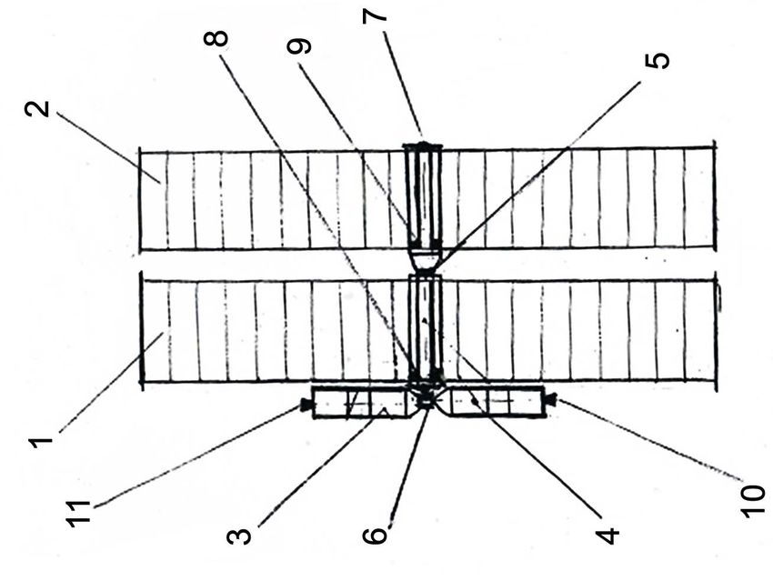
The design of the train is shown on Figure 4—longitudinal section and on Fig-
ure 5—cross section.
1) The front orbital module MZ-1.
2) The rear orbital module MZ-2.
3) The first takeoff-landing capsule (TLC-1).
DOI: 10.4236/aast.2021.62007 102 Advances in Aerospace Science and TechnologyA. Rubinraut
Figure 4. Design of the space train MARSZUG (longitudinal section).
Figure 5. Design of the space train MARSZUG (cross section).
4) The second takeoff-landing capsule (TLC-2).
5) The case of the front orbital module MZ-1.
6) The case of the rear orbital module MZ-2.
The cases of the rockets MZ-1 and MZ-2 are cylinder-shaped and are made of
carbon.
Inside of the cases 5 and 6 there are tanks-cryostats with a working substance
for the operation of superconducting electrorocket engines. Outside tanks-cryostats
have screen-vacuum insulation.
In the end disks the holes are made, in which the electrorocket engines 7 and 8
are being installed.
The end discs also have a telescopic rod-moving system 19, which is used for
unfolding of the solar batteries 9 and 10 along transverse axis.
To fill tanks-cryostats with liquid hydrogen, in the end part of the orbital
modules cryogenic pumps 11 and 12 are installed.
The superconducting bearing 13, mounted in the end part of the module MZ-1,
serves to rotate the shaft with nozzle 18. The shaft nozzle 18 has two docking
units 15 and 16, with which help the takeoff-landing capsules 3 and 4 are dock-
ing with the front orbital module.
The design of the space train allows by rotation of the take-off and landing
capsules TLC-1 and TLC-2 relative to the main axis to create artificial gravity in
cabin of astronauts during the flight of the train.
The connection of the front orbital module MZ-1 with the rear orbital module
DOI: 10.4236/aast.2021.62007 103 Advances in Aerospace Science and TechnologyA. Rubinraut
MZ-2 is carried out by means of docking during the train assembling in orbit
around the Earth using the docking unit 14. In order to dock the space train with
the space refueller during the refueling of electrorocket engines with liquid hy-
drogen in the orbits of Mars and Earth, in the end part of the rear orbital module
MZ-2 is the docking unit 17 installed.
Autonomous movement of takeoff-landing capsules TLC-1 and TLC -2 when
landing and taking off from the surface of Mars and maneuvering in orbit
around Mars and around the Earth is carried out with the help of hydrogen-
oxygen rocket engines 20 and 21.
4. Design of Combined Superconducting Electrorocket
Engine Type MARS-K
It should be recalled that the electrorocket engine of type MARS was invented by
the author in 2006 [9]. In 2017, the project of the electric motor was considered
and calculated researches were carried out, which showed that the developed de-
sign will allow creating an electric rocket engine with a high efficiency factor for
space trains that deliver astronauts to the planets of the solar system [10].
For the presented space train project, MARSZUG a new design of the super-
conducting electric rocket engine has been developed which allows creating a
traction force not only on the longitudinal, but also on the cross-axis of the
space train. At the same time, the constructive concept developed in the [10] is
preserved, because it solves the main problem—the creation of the traction force
of the electric motor on the longitudinal axis.
With the help of four electric motors, which create a traction force on the lon-
gitudinal axis, the pitching and yawing of the spacecraft is provided.
To ensure the rotation of the spacecraft, on the butt surface of the electric motor
the working camera 2 (Figure 6) of the additional magnetoplasm rocket engine
is installed.
Figure 6. Design of the main electrorocket engine.
DOI: 10.4236/aast.2021.62007 104 Advances in Aerospace Science and TechnologyA. Rubinraut
Inside the working chamber 2 there are two flat electrodes—anode 3 and ca-
thode 4. The electric field inside the working chamber 2 is created when the vol-
tage on the anode and cathode is applied. To create a magnetic field inside the
working camera 2, a magnetic system is used, which is already installed to create
the traction force on the longitudinal axis of the electric motor.
The magnetic field in the space at the end of the electric motor is created by
the solenoid 1, made of superconductor and placed in cryostat 10 with liquid
hydrogen.
The working substance of the end flat electric motor is a gaseous hydrogen,
which is supplied in the working chamber 19 (Figure 7), which has rectangular
output nozzle 20.
Figure 6 and Figure 7 show, how the vector of electric current I between elec-
trodes, the vector of the magnetic field B, created by the solenoid 1 and the vec-
tor of mechanical thrust F on output of the working chamber of the additional
magnetoplasm engine 19 for creation a torque, are directed.
After a voltage is applied to electrodes 4 and 5, the working substance is io-
nized and an electric current arises. When the current interacts with the mag-
netic field in accordance with the law of the Ampere, the force F, ejecting hy-
drogen ions from the working chamber through the nozzle 20, arises.
Force F creates a reactive thrust in the direction of the transverse axis, which
rotates the space train relative to the longitudinal axis. The working camera of
the additional electric rocket engine has a casing on its outside (Figure 6).
Design of the main electrorocket engine is shown at Figure 6.
6—working chamber.
7—cathode.
8—anode.
9—cryostat case.
10—superconducting exciting winding.
11—electrode sleeve.
12, 13—supply of the working substance through the channels of the sleeve.
14—inter-electrode insulator.
Figure 7. Electromotor Mars in cross-section.
DOI: 10.4236/aast.2021.62007 105 Advances in Aerospace Science and TechnologyA. Rubinraut
Figure 7 shows the electric motor in cross-section.
1—cathode, 2—anode, 3—superconducting cylindrical coil of exciting winding,
4—rectangular superconducting coil of exciting winding, 5—internal cylindrical
case of cryostat, 6—external cylinder, 7—coil mount, 8—cryostat casing, 9—external
cylindrical cryostat casing, 10—bandage of superconductor coil,11—transversal
coil mount support 12—slits of the thermal bridge of the cryostat, 13—insulation
cylinder 14—bandage of cylindrical superconductor coils, 15—the end disk of
the cryostat 16—suspensions of the external disk of the cryostat, 17—vacuum
interlayer of cryostat 18—inner cavity of cryostat with liquid hydrogen, 19—end
flat superconductor engine for creation the traction of rotation, 20—output noz-
zle of the end electrorocket engine with vector diagrams of thrust force, current
and magnetic field.
Figure 8 shows cross-section of a rocket train (in the middle) with assembled
solar panels.
1—tank-cryostat with liquid hydrogen.
2—solar panels made of gallium arsenide.
3—swivel joint of solar panels.
4—external casing of the rocket.
5, 6—longitudinal axial beams of solar panel assembly.
Figure 9 shows the cross-section of the rocket along the front end shield, on
which the electrorocket engines are installed.
1—tank-cryostat to store the working substance. Filled with liquid hydrogen.
2—front end disk made of carbon.
3—output nozzle of the electric rocket engine, which creates the thrust along
the longitudinal axis.
Figure 8. Cross-section of rocket train with assembled solar panels.
Figure 9. Cross-section of the rocket along the front end shield.
DOI: 10.4236/aast.2021.62007 106 Advances in Aerospace Science and TechnologyA. Rubinraut
4—outer shell of the electrorocket engine cryostat.
5—inner cavity of the tank-cryostat.
6, 7—transverse telescopic thrust for solar cell deployment.
8—end flat electrorocket engine, creating anti-clockwise rotation thrust.
9—end flat electrorocket engine, creating clockwise rotation thrust.
Figure 9 shows that the thrust vectors of the rotation of engines 8 and 9 are
directed oppositely. The accepted in the project engines arrangement allows you
to adjust the rotation process around the longitudinal axis.
To maximize the use of solar energy, in the project an automatic system for
Sun tracking has developed. By controlling the thrust of electric motors 8 and 9,
the automatic system continuously works out the position of the train in space in
such a way that the solar rays are always directed perpendicular to the surface of
the solar cell.
The parameters of the electrorocket engine creating longitudinal thrust are shown
in Table 1.
The parameters of the electrorocket engine, which creates the traction force of
rotation (Figure 6 and Figure 7) are shown in Table 2.
5. The Design of the Rocket MZ-1 Case
Figure 10 shows the design of the rocket MZ-1 case.
1—outer shell of the case made of carbon.
2—tank-cryostat with working substance—liquid hydrogen.
3—front end shield.
4—solar battery panel made of gallium arsenide.
Table 1. The parameters of the electrorocket engine creating longitudinal thrust.
Traction force 40 N
Power 400 kW
Current 400 А
Voltage 1000 V
Efficiency 94%
Specific impulse 6000 sec
Expenditure of the working substance 0.6 g/sec
Working substance expiration rate 10 km/sec
Anode diameter 170 mm
Cathode diameter 40 mm
Magnetic induction 1.5 Т
External cylinder diameter 650 mm
Anode length 90 mm
Cathode length 75 mm
External cylinder length 400 mm
DOI: 10.4236/aast.2021.62007 107 Advances in Aerospace Science and TechnologyA. Rubinraut
Figure 10. Design of the rocket MZ-1 case.
Table 2. The parameters of the electrorocket engine, which creates the traction force of
rotation.
Traction force 10 N
Power 96 kW
Current 120 А
Voltage 800 V
Efficiency 91%
Specific impulse 6000 sec
Expenditure of the working substance 0.2 g/sec
Working substance expiration rate 10 km/sек
Magnetic induction 1.7 Т
Height electrode 4 120 mm
Length electrode 4 120 mm
Distance between electrodes 50 mm
5—telescopic system of the solar panels spreading.
6—electrorocket engine MARS-M.
7—the outer case of the superconductor bearing of artificial gravity system.
8—shaft of superconductor bearing.
9—end nozzle with docking unit to connect the train with the TLC-1.
10—rear end shield.
DOI: 10.4236/aast.2021.62007 108 Advances in Aerospace Science and TechnologyA. Rubinraut
11—cryogenic pump to pump liquid hydrogen into the tank-cryostat.
12—pipeline to feed hydrogen into electrorocket engine.
13—docking unit to connect the rocket MZ-1 with the rocket MZ-2.
14—docking unit to connect the train with TLC-2.
16, 17—hinge joint of solar assembly panels.
The mass of the rocket MZ-1 on Earth—27 tons and the mass of the rocket
MZ-2—25 tons.
6. The Design of the Artificial Gravity Creation System with
the Help of a Superconductor Bearing
Artificial gravity in the astronauts’ cabins of the TLC-1 and TLC-2 takeoff-landing
capsules is created under the influence of centrifugal force when the capsules are
rotating relative to the longitudinal axis of the MZ train.
A new constructive solution of the bearing 7 Figure 10, which works on the
Meisner effect, has been found. The design of the superconductor bearing is
shown on Figure 11.
The bearing consists of moving and fixed cylindrical sleeves mounted along
the train’s axis.
Rotating part 1 is separated from the stationary part 2 by an end clearance 3.
On the rotating part 1 with the help of a protruding shaft 4 the cylinder 5,
made of a monolithic superconductor—the compound yttrium-barium is set.
Outside cylinder 5 a shell 6, made of non-metallic material is located. On the
stationary part 2, with help of the sleeve 7 the cylinder 8 is fixed which consists
of a set of permanent magnets with alternating polarity.
Permanent magnets are made from the compound iron-neodymium-boron.
On the end flanges of the cylinder 8 the magnets 9 and 10 are set, transmitting
axial forces.
When the bearing works, liquid hydrogen is fed into the gap between the ro-
tating cylinder 5 and the cylinder 8.
Once cooled, the cylinder 5 becomes superconducting, and the magnetic field
created by the constant magnets 8, 9 and 10 does not penetrate inside the cy-
linder 5. This creates a lifting force that steadily holds the rotating part of the
bearing 1 on the horizontal axis.
Figure 11. Design of the superconductor bearing.
DOI: 10.4236/aast.2021.62007 109 Advances in Aerospace Science and TechnologyA. Rubinraut
The fixation of rotor 5 on the longitudinal axis is carried out with the help of a
stationary superconducting electromagnet 11, which has a ferromagnetic core
12.
Thanks to the magnetic interaction of the stationary and rotating part, the
superconductor bearing shown on Figure 11, has no loss of energy on friction,
which provides minimal energy consumption to create artificial gravity in the
astronauts’ cabin.
7. The Takeoff—The Space Landing Capsule (TLC) of Train
MARSZUG
The capsule is designed to move five astronauts from Earth’s orbit to Mars orbit
and back into Earth orbit. The design of the TLC is shown on Figure 12.
1—Chemical hydrogen-oxygen rocket engine with thrust of 20 ton and spe-
cific pulse of 400 seconds.
2—The bottom of capsule rocket case.
3—Liquid oxygen tank.
4—Liquid hydrogen tank.
5—Chemical rocket engine for maneuver.
6—Tank cryostat with liquid hydrogen.
7—Cabin crew of the expedition.
8—Superconducting solenoid to create a magnetic field that protects astro-
nauts from the flow of charged particles.
9—Docking unit to connect with the shaft of the superconducting bearing.
10—Tunnel and gateway to get out of the rocket.
11—Parachute system for capsule landing on the surface of Mars.
12—The instrument container.
13—Power ring of the landing tripod.
Figure 12. Design of takeoff-landing capsule.
DOI: 10.4236/aast.2021.62007 110 Advances in Aerospace Science and TechnologyA. Rubinraut
14—Damper of landing upright.
15—The shoe of the landing upright.
16—External case of TLC.
TLC mass on Earth—26 tons.
TLC length—14 m.
TLC external diameter—6 m.
8. The Refueller of the Space Train MZ by Liquid Hydrogen
Designed to refuel superconductor electrorocket engines of the space train by
working substance—liquid hydrogen. It’s shown at Figure 13.
The refueller is constantly on the scientific research base (SRB), located at the
north pole of Mars. With the help of an ice melter, an electrolyzer and a liquefi-
er, at the base the liquid hydrogen is produced, which from storage tank-cryostat
is poured into the tanks of the refueller.
At Figure 13:
1—Chemical hydrogen -oxygen rocket engine with thrust of 20t and specific
pulse of 400 seconds.
2—The bottom of rocket case.
3—Tank-cryostat with liquid oxy.
4—The tank-cryostat with liquid hydrogen for takeoff into Mars orbit.
5—Chemical rocket engine for maneuver.
6—The tank -cryostat with liquid hydrogen to refuel space train.
7—The outer cylindrical shell of the cryogenic tank made of carbon.
8—The outer cone of refueller shell.
9—Docking unit for connection with the space train (end flap).
Figure 13. Refueller of the space train MARSZUG by liquid hydrogen.
DOI: 10.4236/aast.2021.62007 111 Advances in Aerospace Science and TechnologyA. Rubinraut
10—Cryogenic pipeline to supply liquid hydrogen to the tank-cryostat of the
train.
11—Computerized engine control system for take-off from the Mars surface,
entering the orbit of Mars and dock the refueller with the space train.
12—Parachute to brake the refueler when landing on the surface of Mars.
13—Power ring of the landing tripod.
14 –The landing upright damper.
15—The shoe of the landing upright.
16—Cryostat tank bottom.
The mass of the refueller on Earth—25 t.
Length—14 m External diameter—6 m.
9. Conclusions
1) A complex of works on the creation of a space train MARSZUG for regular
delivery of astronauts to the planet Mars has been performed.
2) The design of the space train, which is formed in the orbit of the Earth by
docking of individual modules being delivered by existing rocket carriers, has
been developed.
3) The movement from Earth orbit to Mars orbit is carried out with the help
of the combined system of superconductive electric magnetoplasma engines
MARS-K, which provides the usage of solar energy to create thrust with maxi-
mum efficiency.
4) The new design solution with two takeoff-landing capsules allows delivery
to Mars 10 astronauts which are located in the cabins equipped by the system of
artificial gravity and magnetic protection against cosmic radiation. The time du-
ration of the space train movement between orbits will be 40 days.
Conflicts of Interest
The author declares no conflicts of interest regarding the publication of this pa-
per.
References
[1] (2017) Die Suche nach Lebenslauf dem Mars Mission Exo. Space, 17-21.
[2] Smith, P.H., et al. (2009) H2O at the Phoenix Landing Site. Science, 325, 58-61.
https://doi.org/10.1126/science.1172339
[3] Onken, J. (2016) Die größte Rakete der Welt. Space, 62-69.
[4] Rubinraut, A. (2020) Expedition to Mars North Pole and Creation There a Scientific
Research Base. Advances in Aerospace Science and Technology, 5. 20-43.
https://doi.org/10.4236/aast.2020.51002
[5] (2017) Iglus auf dem Mars. Space, 80.
[6] (2017) Mars Rover. Space, 70-71.
[7] Rubinraut, A. (2016) The Expedition to Jupiter. International Journal of Emerging
Technology and Advanced Engineering, 6.
[8] Rubinraut, A. and Moonplane. A. (2019) Spacecraft for Regular Delivery of Astro-
DOI: 10.4236/aast.2021.62007 112 Advances in Aerospace Science and TechnologyA. Rubinraut
nauts onto the Moon. Advances in Aerospace Science and Technology, 4. 43-56.
https://doi.org/10.4236/aast.2019.43004
[9] Rubinraut, A. (2013) Elektrischer Düsenantrieb für dem Flug zum Mars. Patent
No.102006022 559 DPMA.
[10] Rubinraut, A. (2017) The Study on Electrorocket Engine for the Future. Advances
in Aerospace Science and Technology, 2, 1-16.
https://doi.org/10.4236/aast.2017.21001
DOI: 10.4236/aast.2021.62007 113 Advances in Aerospace Science and TechnologyYou can also read