JEFFERSON'S TOPEKA - MCP Group
←
→
Page content transcription
If your browser does not render page correctly, please read the page content below

JEFFERSON'S TOPEKA

      COPYRIGHT © 2021
      HIVE DESIGN COLLABORATIVE, INC.

      HIVE DESIGN COLLABORATIVE, INC.
      1617 WALNUT ST., KANSAS CITY, MO 64108
      816.581.6363
GENERAL PROJECT NOTES:
1. ALL WORK SHALL BE DONE IN ACCORDANCE WITH THE GOVERNING LAWS AND CODES, AND C) NO MODIFICATIONS / REVISIONS / CHANGES SHALL BE UNDERTAKEN UNLESS 10. GC, SUBCONTRACTORS, AND ALL VENDORS ARE TO VERIFY ALL CLEARANCES (CORRIDORS,
IN ACCORDANCE WITH AUTHORITIES HAVING JURISDICTION. SPECIFICALLY SO INSTRUCTED AND APPROVED BY OWNER. STAIRS, ELEVATORS, ETC.) REQUIRED FOR DELIVERIES AND PASSAGE OF ALL JOB
D) DURING COURSE OF PROJECT, GENERAL CONTRACTOR SHALL MAKE EVERY EFFORT MATERIALS/EQUIPMENT.
2. GC TO VERIFY ALL DIMENSIONS AND NOTIFY ARCHITECT OF ANY DISCREPANCIES PRIOR TO TO FULLY INFORM ALL CONCERNED PARTIES REGARDING DECISIONS/ACTIONS TAKEN
CONSTRUCTION. CONTRACTOR ACKNOWLEDGES REVIEW OF CONDITIONS AND INTENT OF ALL WHICH, IN ANY WAY, MIGHT AFFECT ANY SAID CONSTRUCTION CONDITIONS. 11. ALL NECESSARY WOOD BLOCKING / GROUNDS, ETC., ARE TO BE SUPPLIED AS FIREPROOFED
CONSTRUCTION DOCUMENTS UPON SUBMITTING BID. ELEMENTS. GC SHALL FULLY COORDINATE SETTING/PLACEMENT OF THESE ELEMENTS AS REQUIRED
7. ALL EXISTING HOLES/CRACKS IN SLAB AND THOSE RESULTING FROM THE CONSTRUCTION BY LOCAL CODE/BUILDING OR SURROUNDINGS.
3. CALCULATE AND MEASURE REQUIRED DIMENSIONS. DO NOT SCALE DRAWINGS UNLESS PROCESS SHALL BE FILLED/REPAIRED AND THE SURFACE PATCHED SMOOTH AND LEVEL WITH A) GROUND/BLOCKING MAY NOT BE WHOLLY SHOWN ON DRAWINGS AND GOOD
OTHERWISE INDICATED. ALL DIMENSIONS TO BE TAKEN FROM DESIGNATED DATUM POINT. ADJACENT FLOOR SURFACE, IN A MANNER ACCEPTABLE TO OWNER AND ARCHITECT CONSTRUCTION PRACTICE SHALL GOVERN/DETERMINE SAID USE WHERE A QUESTION ARISES.
WRITTEN DIMENSIONS TAKE PRECEDENCE OVER GRAPHIC REPRESENTATION. DETAIL B) GC TO PAY PARTICULAR ATTENTION TO ALL LOCATIONS OF DRYWALL PARTITION
DIMENSIONS TAKE PRECEDENCE OVER PLAN DIMENSIONS. 8. GC SHALL BE RESPONSIBLE FOR FIELD MEASURING OF EXISTING CONDITIONS PRIOR TO CONSTRUCTION THAT ABUT OR RECEIVE MILLWORK OR CABINET WORK CONSTRUCTION.
START OF WORK AND DURING CONSTRUCTION, AS NECESSARY, TO ASSURE CONSTRUCTION INTERNAL WOOD BLOCKING SHALL BE SUPPLIED FOR STURDY ANCHORAGE AT INTERSECTIONS
4. ALL ITEMS SUPPLIED BY THE OWNER AND INSTALLED BY THE CONTRACTOR WILL BE ADHERENCE TO DRAWINGS. BY ENTERING INTO A CONSTRUCTION CONTRACT FOR THIS WORK, OF WOOD/GLASS BORROWED LIGHT PARTITIONS AND ADJACENT DRYWALL CONSTRUCTION AS
COORDINATED BY THE CONTRACTOR FROM DELIVERY TO INSTALLATION. GC SHALL INDICATE HIS FAMILIARITY WITH THE SITE/FIELD CONDITIONS. REQUIRED.
A) ALL "HOLD" DIMENSIONS SHALL BE MONITORED TO ASSURE CORRECTNESS.
5. DIMENSIONS ON DRAWINGS ARE TO FACE OF STUD AND CENTERLINE OF COLUMNS UNLESS B) ANY DIMENSION REVISIONS/MODIFICATIONS ARE TO BE BROUGHT TO ATTENTION OF 12. THE CONTRACTOR SHALL INSTALL DUST PROOF CURTAINS BETWEEN THE AREAS TO BE
OTHERWISE NOTED. THE ARCHITECT FOR REVIEW/APPROVAL. REMODELED AND THE AREAS TO REMAIN UNTIL ALL DUST PRODUCING WORK IS COMPLETED AND
ALL DEBRIS IS CLEANED UP.
6. THE GENERAL CONTRACTOR (GC, HEREAFTER) UPON SIGNING THE OWNER/GC AGREEMENT, 9. ALL VERTICAL DIMENSIONS SHALL BE TAKEN FROM "BENCH MARK" OR OTHER SIMILAR GUIDE
ACCEPTS THE CD (INCLUDING THESE DRAWINGS W/ THE INCLUDED NOTES & DESCRIPTIVE ESTABLISHED PRIOR TO START OF CONSTRUCTION. HIGH POINTS, LOW POINTS, 13. PROTECT THE AREAS OF THE BUILDING NOT BEING REMODELED FROM DAMAGE AT ALL TIMES.
MATERIAL) & AGREES TO EXECUTE THE NECESSARY WORK IN MANNER DESCRIBED THEREIN. IRREGULARITIES IN FLOOR SLAB, PARTICULARLY, WHICH COULD IN ANY WAY AFFECT
A) UPON EXAMINATION / FAMILIARIZATION OF CD & JOB SITE VISIT, ANY DISCREPANCIES, FABRICATION/INSTALLATION WORK OF OTHER TRADES OR VENDORS (I.E., CABINET 14. KEEP ACCESS TO EMERGENCY EXITS AVAILABLE AT ALL TIMES
OMISSIONS, AMBIGUITIES AND/OR CONFLICTS NOTED, SHALL BE BROUGHT TO THE CONTRACTORS), SHALL BE BROUGHT TO THE ATTENTION OF THE ARCHITECT.
ATTENTION OF ARCHITECT IN WRITING, FOR CORRECTION. A) VARIATIONS IN FLOOR LEVEL IN EXCESS OF 1/2" FOR EVERY 10'-0" IN EVERY DIRECTION 15. CONTRACTOR SHALL REMOVE ALL DEBRIS FROM THE PROJECT SITE AND DISPOSE IN A LICENSED PROJECT LOCATION
B) ANY ELEMENT, WHATSOEVER, REQUIRED BY BUILDING TO BE INCORPORATED IN WILL REQUIRE LEVELING OF SLAB BY G.C. LEVELING OF SLAB TO BE DONE AS REQUIRED LANDFILL
CONSTRUCTION BUT NOT SPECIFIED IN CD SHALL BE BROUGHT TO ATTENTION OF READY TO RECEIVE FLOOR FINISHES, (I,E, VINYL TILE FLOORS, CARPETING, ETC). G.C. TO
ARCHITECT FOR REVIEW/ACTION. VERIFY SLAB CONDITION PRIOR TO BID SUBMISSION AND CONTACT LANDLORD.
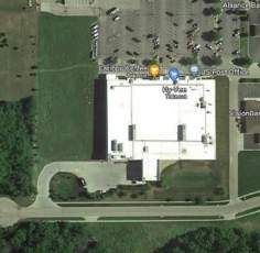
GENERAL NOTES VICINITY MAP
12" = 1'-0"
OFF. Office
Above Finish Floor O.C. On Center
A.F.F. Acoustical FOC Face of Concrete OPNG. Opening SHEET INDEX SHEET INDEX
ACOUS. Acoustical Ceiling FOF Face of Finish OPP. Opposite
ACT Tile FOS Face of Studs O.H. Opposite Hand G000 COVER
ADJ Adjacent, Adjustable FOW Face of Wall O.D. Outer Diameter (Dim.) DIVISION 01: GENERAL DIVISION 05: METALS
A/C Air Conditioning FV Field Verify OFD Over Flow Drain G001 SYMBOLS, ABBREVIATIONS, MEP111 SPECIFICATIONS
ALT Alternate FIN. Finish O.A. Overall DETAIL/ SECTION STEEL/ IRON (LARGE SCALE) DRAWING INDEX
ALUM Aluminum F.A. Fire Alarm 00
MEP112 SPECIFICATIONS
O.R.D. Overflow Roof Drain
ANG Angle F.E. Fire Extinguisher A000 G002 WALL TYPES MEP113 SPECIFICATIONS
APPROX Approximate F.E.C. Fire Extinguisher Cabinet PT Paint ALUMINUM
F.R. Fire Rated, Fire Retardant PTD. Painted
G003 ACCESSIBILITY GUIDELINES MEP114 SPECIFICATIONS
ARCH Architect(ural) DETAIL REFERENCE
AD Area Drain F.S.P. Fire Stand Pipe PR. Pair A0
A000
G111 CODE FLOOR PLAN MEP211 FIRE STOPPING DETAILS
ASPH Asphalt F.V.C. Fire Valve Cabinet PNL Panel, Panelboard OTHER METALS
F.P. Fireproof PERF. Perforated 00 G500 SHEET SPECS
BSMT Basement DIVISION 06: WOOD AND
FPSC Fireproof Self Closing PERP Perpendicular A000 BUILDING SECTION G501 SHEET SPECS
BM Beam
FIX, FIXT Fixture PLAS Plaster PLASTICS DM111 DEMOLITION FLOOR PLANS
BYND Beyond G502 SHEET SPECS MECHANICAL
FLASH Flashing P-LAM Plastic Laminate 00
1617 WALNUT STREET, KANSAS CITY, MO 64108
BITUM. Bituminous WOOD (DIMENSION) (THROUGH MEMBER)
FL, FLR Floor PL. Plate
BLK Block G503 SHEET SPECS M111 FLOOR PLANS MECHANCIAL
JEFFERSON'S TOPEKA
F.D. Floor Drain PLYWD. Plywood A000
BLKG Blocking BUILDING ELEVATION REFERENCE
BD Board
FLUOR. Fluorescent PT. Point G504 SHEET SPECS M211 MECHANICAL DETAILS
FT,' Foot, Feet PVC Polyvinyl Chloride 00
WOOD (DIMENSION) (INTERRUPTED MEMBER)
BOT Bottom
FTG. Footing PSF Pounds per Sq. Foot INTERIOR ELEVATION
G601 UL ASSMEBLIES M212 MECHANICAL SCHEDULES GEN.
BO Bottom of A000
B.C. Bottom of curb
FDN. Foundation PC Precast Concrete NOTES & SYMBOLS
PLYWOOD
HIVE DESIGN COLLABORATIVE, INC.
F.A.I. Fresh Air Intake PREFAB. Prefabricated
BOS Bottom of steel
F.S. Full Size PRT Pressure Treated C-1 COVER SHEET M213 MECHANICAL SCHEDULES GEN.
BLDG Building XXXXX
NOTES & SYMBOLS
F.B.O. Furnished by Others PROJ Project ELEVATION DESIGNATION C-2 DEMOLITION PLAN
BO By Others/Owner XXXXX WOOD (FINISH)
FURR. Furring PROP Property
CAB Cabinet C-3 SITE PLAN M311 KITCHEN DRAWINGS
2915 SW WANAMAKER ROAD
GALV. Galvanize
CPT Carpet QTY Quantity
G. Gas
Q.T. Quarry Tile
XXX DOOR TAG C-4 GRADING PLAN M312 KITCHEN DRAWINGS
C.I.P. Cast-In-Place HARDBOARD
GA. Gauge
C.B. Catch Basin M313 KITCHEN DRAWINGS
TOPEKA, KANSAS 66614
CLG. Ceiling
G.C. General Contractor R., RAD. Radius C-5 UTILITY PLAN
CEM. Cement
GL. Glass RE, REF. Reference X INTERIOR PARTITION TYPE
PARTICLE BOARD C-6 EXISTING DRAINAGE AREA MAP M314 KITCHEN DRAWINGS
G.F.R.C. Glass Fiber Reinforced Concrete REINF. Reinforced
CTR Center
G.F.R.G. Glass Fiber Reinforced Gypsum R.C.P. Reinforced Concrete Pipe ROOM C-7 PROPOSED DRAINAGE AREA M315 KITCHEN DRAWINGS
CL Center Line NAME
GR. Grade R.A. Relieving Angle ROOM NUMBER DESIGNATION M316 KITCHEN DRAWINGS
C/C Center to Center
GSF Gross Square Feet
000
SOLID SURFACE MATERIAL MAP
CER. Ceramic REQ. Required
GND Ground C-8 BMP AND DETENTION PLAN M317 KITCHEN DRAWINGS
816.581.6363
CT. Ceramic Tile R.H. Right Hand
GYP. Gypsum GENERAL NOTES DIVISION 07: THERMAL & MOISTURE PROTECTION
C. OF O. Certificate of Occupancy
GYP. BD Gypsum Wallboard
R. Riser 1
C-9 EROSION CONTROL PLAN M318 KITCHEN DRAWINGS
C. Channel RD. Road
RIGID INSULATION M319 KITCHEN DRAWINGS
C.O. Cleanout HDWR Hardware R.D. Roof Drain C-10 EROSION & POLLUTION
HDWD Hardwood RM.. Room 1 CONSTRUCTION NOTE
CL. Clear CONTROL DETAILS 1 M320 KITCHEN DRAWINGS
CLR Clear HD Head R.O. Rough Opening
FIRE SAFING INSULATION C-11 EROSION & POLLUTION M321 KITCHEN DRAWINGS
CLOS. Closet HTR Heater RB Rubber Base
SAB Sound Attenuation Batt A CENTER LINES OF COLUMN GRIDS
CW Cold Water HVAC Heating, Venting, Air Conditioning
SCHED. Schedule
CONTROL DETAILS 2 M322 KITCHEN DRAWINGS
COL. Column HT. Height
SEC. Second BLANKET INSULATION C-12 STANDARD DETAILS
CONC Concrete HPC High Performance Coating M323 KITCHEN DRAWINGS COPYRIGHT © 2021
H.P. High Point SECT. Section 1 HR - FIRE RATED ASSEMBLY
CMU Concrete Masonry Unit
SHT. Sheet 2 HR - FIRE RATED ASSEMBLY C-13 RAMP & WALK DETAILS M324 KITCHEN DRAWINGS HIVE DESIGN COLLABORATIVE, INC.
CONF. Conference HWY Highway
SIM. Similar 2 HOUR SMOKE - FIRE RATED ASSEMBLY LOOSE FILL INSULATION
CONST. Construction H.C. Hollow Core C-14 TYPE II-P INLET DETAILS M325 KITCHEN DRAWINGS
H.M. Hollow Metal S.C. Solid Core 4 HOUR - FIRE RATED ASSEMBLY seal/signature
C.M. Construction Manager
HORIZ. Horizontal STC Sound Transmission Coefficient SMOKE - FIRE RATED ASSEMBLY
CONT Continuous SEALANT W/ BACKER ROD
H.B. Hose Bibb S South L-1 LANDSCAPE PLAN
CONTR Contractor
SPKR. Speaker MP111 ROOF PLAN MECHANICAL &
C.J. Control Joint HW Hot Water
CONV. Convector HR Hour SPEC. Specification NEW WALL PLUMBING
S.F.P. Spray on Fireproofing MEMBRANE WATERPROOFING &
CG Corner
Dark Guard IN, " Inside SQ. Square DRAINAGE COMPOSITE D111 DEMOLITION FLOOR PLANS
CORR.
DK Corridor
Decibel INC. Include S.F. Square Feet EXISTING WALL FP111 FLOOR PLANS FIRE
DB Degree I.D. Inside Diameter S.S. Stainless Steel
DEG. Department INSUL. Insulation ST Stair SPRAY-ON FIREPROOFING AS111 ARCHITECTURAL SITE PLAN PROTECTION
DEPT. Dept. Of Building INT. Interior STD. Standard DIVISION 03: CONCRETE AS121 ENLARGED SITE DETAILS
D.O.B. Dept. Of Environmental STA Station DIVISION 08: DOORS & WINDOWS
D.E.P. Protection JAN Janitor STL Steel DP111 DEMOLITION FLOOR PLANS
J.C. Janitor's Closet CAST-IN-PLACE CONCRETE GLASS INSULATING
DTL. Detail STOR. Storage
A111 FLOOR PLANS PLUMBING
DIA. Diameter JT. Joint ST. Street
DIFF. Diffuser JST Joist STRUCT. Structural A112 ROOF PLAN P111 FLOOR PLANS PLUMBING 07.26.21
PRECAST CONCRETE GLASS ELEVATION
DIM. Dimension SUSP. Suspended P112 FLOOR PLANS PLUMBING
DW Dishwasher KIT. Kitchen SYM Symmetrical A121 ENLARGED FLOOR PLANS
DISP. Dispenser K.O. Knock Out P211 PLUMBING DETAILS project number 2020-076
TEL. Telephone PRECAST CONCRETE WALL PLASTIC GLAZING
A211 EXTERIOR ELEVATIONS
DR Door T.V. Television
D.O. Door Opening A611 REFLECTED CEILING PLAN P212 PLUMBING DETAILS
LS Life Safety TEMP. Temporary
DBL. Double LAM. Laminate, Laminated THK Thick, Thickness P213 PLUMBING SCHEDULES GEN. date 07.26.21
DN Down
PRECAST CONCRETE COLUMN NEW DOUBLE DOOR A711 INTERIOR ELEVATIONS
LAV. Lavatory T.&G. Tongue and Groove NOTES & SYMBOLS
DWG(S) Drawing, Drawings L.H. Left Hand T.O. Top Of A712 INTERIOR ELEVATIONS
D.F. Drinking Fountain L. Length T.O.B. Top Of Beam P214 PLUMBING RISER DIAGRAMS issued for PERMIT
LT Light T.O.C. Top Of Curb
CAST-IN-PLACE CONCRETE WALL NEW SINGLE DOOR A713 INTERIOR & CASEWORK
EA Each & CAST-IN-PLACE COLUMN
ELEVATONS P311 PLUMBING SCHEDULES GEN.
EW Each Way L.W. Lightweight T.O.S. Top Of Sidewalk rev date description
E East L.P. Low Point T.O.W. Top Of Wall NOTES & SYMBOLS
T Tread DIVISION 04: MASONRY NEW SWINGING DOOR A801 FF&E PLAN
EPDM Elastomeric Roof Membrane MH Manhole
ELECT Electric, Electrical
MFR, MANUF.Manufacturer
TYP. Typical A901 FINISH LEGEND & SCHEDULE
TW Through wall BRICK DE111 DEMOLITION FLOOR PLANS
ELEC. Electrical M.O. Masonry Opening NEW DOUBLE ACTING DOOR
E.P. Electrical Panelboard
MATL Material
ELECTRICAL
EL. Elevation UNFIN. Unfinished S01 GENERAL NOTES
ELEV. Elevator
MAX Maximum U.N.O. Unless Noted Otherwise CONCRETE MASONRY UNIT E111 FLOOR PLANS POWER
EMER. Emergency
MECH. Mechanical EXISTING DOUBLE DOORS S02 GENERAL NOTES
MEPFP Mechanical, Electrical, Plumbing, Fire Protection E112 ENLARGED PLANS POWER
ENCL. Enclosure V.I.F. Verify in Field S03 NEW RETAINING WALL, STAIRS,
M.E.R. Mechanical Equipment Room VERT. Vertical CUT STONE E211 FLOOR PLANS LIGHTING
EQ. Equal
EQ, EQUIP. Equipment
MDF Medium Density Fireboard VEST. Vestibule EXISTING SINGLE DOOR DOOR HEADER
MEMB. Membrane V.C.P. Vetrified Clay Pipe E311 FLOOR PLANS SYSTEMS
EXIST. Existing
MTL Metal CAST STONE S04 NEW PATIO SLAB, STRING
EXP Expansion MEZZ. Mezzanine
VCT Vinyl Composition Tile DIVISION 09: FINISHES LIGHTING BOLLARDS E411 ELECTRICAL DETAILS
E.J. Expansion Joint VWC Vinyl Wallcovering
EXT. Exterior
MIN. Minimum LATH AND PLASTER
S05 RTU PLAN E412 ELECTRICAL DETAILS
MIR Mirror W Water BRICK PAVER
EIFS Exterior Insulation Finish System
MISC. Miscellaneous W.C. Water Closet E511 ELECTRICAL SCHEDULES GEN.
MTD. Mounted WR. Water Resistant GYPSUM BOARD NOTES & SYMBOLS
MTG. Mounting WP. Waterproofing LIMESTONE
MULT.
N.R.C.
Multiple
Noise Reduction Coefficient
WT
WWF
Weight
Welded Wire Fabric CERAMIC TILE
E512 ELECTRICAL SCHEDULES GEN.
NOTES & SYMBOLS
SYMBOLS,
NOM.
N
Nominal
North
W
W.F
West
Wide flange
QUARRY TILE
CEILING PANEL
ABBREVIATIONS,
N.A. Not applicable W Width Q101 EQUIPMENT PLAN
NIC
N.I.C.
Not in Contact
Not in Contract
WIN
W, W/O
Window
With, Without
GROUT
Q102 EQUIPMENT PLAN DRAWING
NTS
N.T.S.
Not to Sale
Not to Scale
WD. Wood CARPET
INDEX
NO. NUM, # Number
YD Yard
sheet number
ABBREVIATIONS SYMBOLS DRAWING INDEX
1/4" = 1'-0" 12" = 1'-0"
G001
1617 WALNUT STREET, KANSAS CITY, MO 64108
JEFFERSON'S TOPEKA
HIVE DESIGN COLLABORATIVE, INC.
2915 SW WANAMAKER ROAD
TOPEKA, KANSAS 66614
816.581.6363
COPYRIGHT © 2021
HIVE DESIGN COLLABORATIVE, INC.
seal/signature
WALL TYPE KEY:
P3A-__
DESIGNATION
SPECIAL DESIGNATION.
RE: WALL TYPES FOR WALL
B.O. DECK B.O. DECK B.O. DECK B.O. DECK B.O. DECK B.O. DECK DETAILS
07.26.21
WALL HEIGHT
A = FULL HEIGHT project number 2020-076
B = GYP EXTENDS 6"
ABOVE CEILING AND WALL
AND BRACED TO date 07.26.21
STRUCTURE ABOVE
FINISH CLG FINISH CLG FINISH CLG FINISH CLG FINISH CLG FINISH CLG C = PARTIAL HEIGHT
(RE: ELEVATIONS)
issued for PERMIT
RE: RCP FOR RE: RCP FOR RE: RCP FOR RE: RCP FOR RE: RCP FOR
SCHEDULED CEILING SCHEDULED CEILING SCHEDULED CEILING SCHEDULED CEILING SCHEDULED CEILING
rev date description
RE: ELEVATIONS FOR HEIGHT
ASSEMBLY ASSEMBLY ASSEMBLY ASSEMBLY ASSEMBLY STUD SIZE
0 = 7/8" HAT CHANNEL or
3/4" WOOD FURRING STRIP
1 = 1 5/8" METAL STUD
2 = 2 1/2" METAL STUD or
1 1/2" WOOD STUD
3 = 3 5/8" METAL STUD
4 = 4" METAL STUD or
3 1/2" WOOD STUD or
3 5/8" CMU
6 = 6" METAL STUD or
FINISH FLR FINISH FLR FINISH FLR FINISH FLR FINISH FLR FINISH FLR 5 1/2" WOOD STUD or
5 5/8" CMU
8 = 8" METAL STUD or
7 5/8" CMU
10 = 9 5/8" CMU
12 = 11 5/8" CMU
P6A-1 P3C-1 P3B-1 P1B-1 P0B-1 P3A-1
WALL TYPE DESIGNATION
6" INTERIOR WALL TO B.O. STRUCTURE
(1) LAYER 5/8" GYP. BD. ON EACH SIDE OF 20
3 5/8" INTERIOR WALL - PARTIAL HEIGHT
(1) LAYER 5/8" GYP. BD. ON EACH SIDE OF 20
3 5/8" INTERIOR WALL FURRING TO B.O. STRUCTURE
(1) LAYER 5/8" GYP. BD. ON ONE SIDE OF 20 GA. 3 5/8"
1-5/8" INTERIOR WALL FURRING TO B.O. STRUCTURE
(1) LAYER 5/8" GYP. BD. TO B.O. DECK ANCHORED TO
ADD 5/8" GYP BOARD TO EXISTING WALL
(1) LAYER 5/8" GYP. BD. TO B.O. DECK
3 5/8" INTERIOR WALL TO B.O. STRUCTURE
(1) LAYER 5/8" GYP. BD. ON EACH SIDE OF 20
M = MASONRY
P = GYP BD PARTITION
X = CUSTOM
WALL TYPES
GA. 6" METAL STUDS TO B.O. DECK @ 16" GA. 3 5/8" METAL STUDS @ 16" O.C. RE: METAL STUDS TO B.O. DECK @ 16" O.C. 20 GA. 1-5/8" MTL CHANNELS @ 16" O.C. ANCHORED TO EXISTING MTL STUD WALL GA. 3 5/8" METAL STUDS TO B.O. DECK @ 16"
O.C. ELEVATIONS FOR HEIGHT O.C.
* EXTERIOR WALL ASSEMBLIES SHOWN IN WALL
SECTIONS AND DETAILS
sheet number
WALL TYPES NOTES
1" = 1'-0" 1/2" = 1'-0"
G002
2X F.R. WOOD 2X F.R. WOOD
BLOCKING BLOCKING
AT PERIMETER OF AT PERIMETER OF
8" ACCESSORY ACCESSORY
2"X10" F.R.
WOOD
BLUE BORDER 2"X10" F.R. AT RECESS OPENINGS IN BLOCKING
GENERAL NOTES - ACCESSIBILITY GUIDELINES:
WOOD FIRE RATED AS REQUIRED
INTERNATIONAL SYMBOL OF BLOCKING AS
1' - 0"
CONSTRUCTION ONLY. 1. NOTE: ALL DIMENSIONS ARE MEASURED
ACCESS (ISA) IN BLUE ON REQUIRED EXTEND GYP. BOARD SURFACE FROM FLOOR, UNLESS NOTED OR SHOWN
WHITE BACKGROUND. CONTINUOUSLY ALONG MOUNTED TOILET OTHERWISE.
MOUNT B.O. SIGN 7'-0" RECESS AS INDICATED BY ACCESSORY 2. ADA UNOBSTRUCTED REACH RANGES: ADA
SEMI-RECESSED
1"
ABOVE ADJACENT WALK DASHED LINE PER SCHEDULE FORWARD REACH = 48” MAX. & 15” MIN. ADA
F.E.C./ TOILET
2"
ACCESSORY PER SIDE REACH = 48” MAX. & 15” MIN.
HANDRAIL OR
SCHEDULE 3. ELEVATORS: STANDARD CALL BUTTONS: 35”
"VAN ACCESSIBLE" GRAB BAR SEMI-RECESSED
(NON-RATED WALLS) TO 48” TO C.L. & PROTRUDE 1” MAX. ADA CALL
SIGN WHEN F.E.C./ TOILET BUTTONS: 42” TO C.L. (TYP.) & 48” MAX. (3/4”
APPLICABLE, SEE SITE ACCESSORY SMALLEST DIM.). ADA VISIBLE SIGNALS: 72”
PLAN 4" MAX. PER SCHEDULE 4" MAX. MIN. TO C.L. (2 1/2” SMALLEST DIM.). TACTILE
4" MAX. SIGNAL ON HOISTWAY: 60” TO BASE
4x4 STEEL PIPE, AS OFCHARACTERS W/ TACTILE STAR & 2” HIGH
NEEDED CHARACTERS.
4. DOOR HARDWARE (TO CENTER OF
SIGN SHALL BE LOCATED IN FRONT OF EACH HARDWARE): STANDARD MOUNTING
DESIGNATED ACCESSIBLE PARKING STALL HEIGHTS: PUSH PLATES = 42", PULL HANDLES
= 42", KNOBS/ LEVERS = 40", PANIC EXIT = 42"
CENTERLINE OF BAR, KICKPLATES: WIDTH =
DOOR WIDTH MINUS 2”, CENTER, HEIGHT =
16” FROM B.O. DOOR. THRESHOLDS:
STANDARD = 1/2" MAX. AT EXT. SLIDING
DOORS = 3/4” MAX., ADA HARDWARE = 34”
MIN. TO 48” MAX.
5. DRINKING FOUNTAINS & EWC'S (TO SPOUT):
STANDARD = 38” MIN., 43" MAX. ADA =36" MAX.
1.5" O.D. HANDRAIL (27" MIN. CLEAR KNEE SPACE)
6. COUNTERTOPS (TO SINK RIM/ COUNTERTOP):
1' - 0" MIN. 1' - 0" MIN. MIRROR ADA = 28” MIN. TO 34" MAX.
PAPER TOWEL 7. WATER CLOSETS (TO TOP OF SEAT):
PASS-THRU DISPENSER STANDARD = 14” TO 15". ADA (TO TOP OF
SOAP DISPENSER
( 4" MAX. PROJ. ) ( 4" MAX. PROJ. ) SEAT) = 17" TO 19”. ADA FLUSH CONTROLS =
4 1/2" MAX. 44" MAX.
8. URINALS (TO RIM): STANDARD = 24" MAX. ADA
6' - 2" MIN. TO TOP OF
2'-10" TO 3'-2"
TOILET =17" MAX. ADA FLUSH CONTROLS = 44" MAX.
1 1/2" MIN.
REFLECTIVE SURFACE
1 1/4" TO 2" PAPER 9. LAVATORIES (TO SINK RIM/ COUNTERTOP):
4" TO 7" 2'-10" TO 3'-2"
TO NOSING
DISPENSER STANDARD = 36" MAX. ADA = 34" MAX. (29"
TOWEL MIN. CLEAR KNEE SPACE)
SANITARY DISPENSER
1 1/2" MIN.
10. MIRRORS (TO B.O. REFLECTIVE SURFACE):
SEE NOTE #16
NAPKIN
2' - 10" TO 3' - 2"
STANDARD = VARIES. ADA = 40" MAX.
4' - 0" MAX.
4' - 0" MAX.
TO BOTTOM OF
11" MIN. DISPOSAL
1617 WALNUT STREET, KANSAS CITY, MO 64108
REFLECTIVE
11. GRAB BARS - ADA (TO TOP OF BAR): WATER
3' - 4" MAX.
4' - 0"
ELECTRIC INTEGRAL
SURFACE
CLOSETS = 33” MIN. TO 36" MAX. SHOWERS =
JEFFERSON'S TOPEKA
HAND DRIER OR WASTE
PAPER TOWEL DISPOSAL 33” MIN. TO 36" MAX. (FROM B.O.SHOWER).
STAIRS - 1/2" RADIUS DIAPER SANITARY BATHTUBS: TOP BAR = 33” MIN. TO 36"
1' - 7" MIN.
AT NOSING DISPENSER WHERE
( 4" MAX. CHANGING NAPKIN APPLICABLE MAX. BOT. BAR = 9” ABOVE T.O. TUB
1 1/4" MAX. PROJ. ) STATION DISPENSER ( 4" MAX. PROJ. ) 12. SHOWER HEADS (FROM FLOOR TO HEAD):
STANDARD = 72" TO 84”. ADA = SPRAY UNIT W/
HIVE DESIGN COLLABORATIVE, INC.
HOSE 60” LONG MIN. ADA = FIXED SHOWER
HEAD = 48” AFF.
13. SHOWER CONTROLS (TO CONTROL AREA):
STANDARD = 48” MAX. (TO TOP). ADA = 38"
2915 SW WANAMAKER ROAD
MIN. TO 48" MAX.
14. SHOWER ROD (FROM FLOOR TO C.L.):
FIRE EXTINGUISHER
TOPEKA, KANSAS 66614
STANDARD = 78" MAX.
CABINET 15. TOILET ROOM PARTITIONS: TOILETS = 12" TO
PLAN BOT. & 70” TO TOP. URINALS = 18" TO BOT. &
CENTERLINE OF PLAN
CABINET HANDLE OR 60” TO TOP
CENTERLINE OF F.E. 16. TOILET PAPER DISPENSERS (TO C.L. OF
OUTLET): STANDARD = 24". ADA = 19” MIN. TO
2'-1" MAX.
2' - 1' MAX.
1'-5" MIN.
1' - 5" MIN.
HANDEL IF HUNG
PLAN 24" MAX.
816.581.6363
INSIDE CABINET
17. WALL MOUNTED SOAP DISPENSERS (TO C. L.
OF PUSH BUTTON): STANDARD = 40". ADA =
4' - 0" MAX.
VARIES. RE: OBSTRUCTED AND
4' - 0" MIN.
4' - 0" MIN.
UNOBSTRUCTED REACH RANGES. ADA SIDE
REACH = 46” MAX. ABOVE SINK INCOUNTER.
CLEAR 18. PAPER TOWEL DISPENSER/ WASTE
CLEAR FLOOR 30" WIDE X 48" CLEAR RECEPTACLE (TO TOWEL SLOT): STANDARD =
FLOOR SPACE FLOOR SPACE. 40" MAX. ADA FORWARD REACH = 48” MAX. &
SPACE (36" WIDE IN AN ALCOVE.) 15” MIN. ADA SIDE REACH = 48” MAX. & 15”
MIN. COPYRIGHT © 2021
19. WARM AIR HAND DRYER (TO PUSH SWITCH): HIVE DESIGN COLLABORATIVE, INC.
LIGHT SWITCH STANDARD = 44" MAX. ADA FORWARD REACH
2' - 6" MIN. 2' - 6" MIN. = 48” MAX. & 15” MIN. ADA SIDE REACH = 48”
MAX. & 15” MIN. seal/signature
THERMOSTAT 20. SANITARY NAPKIN DISPENSER (TO C.L. OF
CENTERLINE OF BRACKET COIN SLOT): STANDARD = 40" MAX. ADA
5 LBS TO OPERATE FORWARD REACH = 48” MAX. & 15” MIN. ADA
SIDE REACH = 48” MAX. & 15” MIN.
WITHOUT TIGHT
TOP OF SINK RIM OR COUNTER
1' - 5" MIN. 1' - 5" MIN. 21. SANITARY NAPKIN DISPOSAL (TO TOP OF
GRASPING, PITCHING
2' - 10" MAX TO HIGHER OF
2" 2' - 1" MAX. 2' - 1" MAX. UNIT): STANDARD = 28" MAX. ADA = 19” MIN.
8" MIN. 8" MIN. OR TWISTING OF
FIRE EXTINGUISHER TO 24" MAX. (TO OPNG.)
WRIST
& STANDARD BRACKET 22. TOILET SEAT COVER DISPENSERS (TO
1' - 0"
TO TOP OF SINK RIM
OPNG.): STANDARD = 40" MAX. ADA
4' - 0" MAX.
4' - 0" MAX.
3' - 8" MAX.
MAX. FORWARD REACH = 48” MAX. & 15” MIN. ADA
4' - 2"
1' - 3" MIN.
2' - 10" MAX.
SIDE REACH = 48” MAX. & 15” MIN.
23. SHELVES: ADA = 48" MAX.
9" MIN.
2' - 3" MIN.
2' - 3" MIN.
1' - 11" MAX.
9" MIN.
24. COAT HOOKS: STANDARD = 68". ADA = 48"
1' - 5" MAX.
MAX. 07.26.21
25. CHALKBOARDS, TACKBOARDS,&
MARKERBOARDS: STANDARD = 32" TO 39” (TO
SECTION (ACCESSIBLE) (STANDARD) B.O. BOARD OR CHALKTRAY). STANDARD = project number 2020-076
80” (RECOMMENDED, TO T.O. BOARD)
LINE OF WHEELCHAIR 11" MIN. LINE OF 11" MIN. 26. THERMOSTATS & CONTROL DEVICES (TO
RECEPTACLE WHEELCHAIR TOP): ADA FORWARD REACH = 48” MAX. ADA date 07.26.21
6" MAX. 6" MAX. SIDE REACH = 48” MAX.
27. LIGHT SWITCHES & CARD READERS (TO C.L.):
LOCATE 6” FROM DOOR JAMB. ADA = 48” MAX. issued for PERMIT
28. CONVENIENCE RECEPTACLES – ELECTRICAL/
TELEPHONE/ DATA (TO C.L.): STANDARD = 18".
4' - 6" MIN. ADA = 15” MIN. rev date description
1 1/2" O.D. (SS OR CHROME) 29. EXIT LIGHTS - WALL MOUNTED: 2" MIN.
VERTICAL GRAB
2' - 8" CLEAR
3' - 0" MIN.
GRAB BAR SUPPORTS 1' - 0" MAX. 3' - 6" MIN. BELOW CEILING. 2” MIN. ABOVE DOOR
BAR 18" MIN FRAME. EQUAL SPACE FROM CEILING TO TOP
250 LBS FORCE (TYP.)
OF FRAME
5' - 0" 39" TO 41"
1 1/2" O.D. (SS OR 30. FIRE EXTINGUISHERS (TO TOP, U.N.O.):
VERTICAL GROSS WT. 40 LBS. OR LESS = 60" MAX.
CHROME)
1' - 6" MAX. VERTICAL GRAB 3'-0" MAX. GRAB BAR 18" GROSS WT. MORE THAN 40 LBS. = 42" MAX.
GRAB BAR SUPPORTS
1'-4" MIN. 1 1/2" O.D. ( SS OR MIN. ADA = 40" MAX. (B.O. CABINET)
BAR 18" MIN. 250 LBS FORCE (TYP.)
CHROME ) 2'-0" MIN. 31. FIRE ALARM PULL STATIONS (TO LEVER):
WATER CLOSET
1' - 6" MIN.
TOILET GRAB BAR SUPPORTS STANDARD = 48" MAX. ADA FORWARD REACH
FLUSH HANDLES
1' - 6"
4' - 11" FOR FLOOR MTD. W.C.
PARTITION
MIN.
= 48” MAX. ADA SIDE REACH = 48” MAX.
4' - 11" FOR FLOOR MTD. W.C.
250 LBS FORCE (TYP.)
4' - 8" FOR WALL MTD. W.C.
4' - 8" FOR WALL HUNG W.C.
SHALL BE LOCATED 32. SMOKE AND/OR HEAT DETECTORS:
3' - 6" MIN.
ON THE TRANSFER 2' - 0" MIN. 1' - 0"
4' - 6" MIN.
STANDARD = CEILING HEIGHT
1 1/2" O.D. (SS OR CHROME) 1 1/2" SIDE OF THE STOOL MIN. 33. HORN/ SPEAKER/ VISUAL SIGNALS:
GRAB BAR SUPPORTS STANDARD = 80” AFF. OR 6” BELOW CEILING -
250 LBS FORCE (TYP.) DISPENSER WHICHEVER IS LOWER.
DISPENSER
TO B.O. BAR
34. ROOM SIGNAGE (TO C.L.): STANDARD = 60”
T.O. OPENING
1 1/2"
2' - 9" TO 3' - 0"
2' - 9" TO 3' - 0"
TO B.O. BAR
39" TO 41"
TO T.O. BAR
39" TO 41"
TO T.O. BAR
4'-0" MAX.
HIGH AFF. & WITHIN 18” OFLATCH SIDE OF
DOOR
B.O. OPENING
1'-6" MIN.
CLEAR
ACCESSIBILITY
1' - 5"
FLOOR
1' - 0"
MAX.
SPACE
7" TO 9" GUIDELINES
B.O. OPENING
1' -4" MIN. 2' - 0" 1' - 6"
NOTE: PARTITION DOOR IS 1' - 4" MIN.
1'-6" MIN.
1' - 6" MAX. 3' - 0"
TO BE LOCATED OPPOSITE VERTICAL GRAB 1' - 6" MAX.
OF W.C. LOCATION BAR 18" MIN. MAX.
5' - 0" CLEAR
sheet number
NOTES
G003
CODE INFORMATION SUMMARY:
SUBJECT DATA REFERENCE
PROJECT CONVERSION OF A FORMER BANK BUILDING (B
DESCRIPTION OCC) INTO A SIT-DOWN RESTAURANT (A-2 OCC)
JURISDICTION CITY OF TOPEKA
STAIR APPLICABLE CODE 2015 INTERNATIONAL BUILDING CODE
1997 UNIFORM CODE FOR BUILDING
45
CONSERVATION
13.5" 2015 UNIFORM MECHANICAL CODE
44" 2017 NATIONAL ELECTRICAL CODE
2018 UNIFORM PLUMBING CODE
2015 INTERNATIONAL FIRE CODE
2015 LIFE SAFETY CODE
STO OFFICE
STO BEER COOLER 007 006 ADA STANDARDS 2010 ADA STANDARDS FOR ACCESSIBLE DESIGN
10' - 0"
008 012 99 SF 61 SF
SECTION 303
300 150
OCCUPANCY CLASS A-2
151 SF
0.33 0.41 SECTION 601
300 CONSTRUCTION TYPE II-B
0.51 14' - 0"
008A
P3A-1 0
ETR
ETR
STRUCTURAL FRAME
DOOR
ETR
BEARING WALLS, EXT. 0
P3A-1 EVENT SPACE
46 ETR P1B-1 FIRE RESISTANCE SECTION 601
004 NON BEARING WALLS 0
9.2"
CORRIDOR 1,430 SF FLOOR CONSTRUCTION 0
36"
005 15
ETR ALCOVE 004A 0
95.93 ROOF CONSTRUCTION
FE 001
ETR ETR AUTOMATIC SPRINKLER EXISTING
009A
ETR
FIRE PROTECTION FIRE ALARM SYSTEM EXISTING CHAPTER 9
MECH GAME ROOM RESTROOMS RESTROOMS
010 ETR 009 FIRE EXTINGUISHER(S) REQUIRED
003 002
140 SF 613 SF
300 15 55' ABOVE GRADE
P1B-1 ALLOWABLE HEIGHT
0.47 40.87 2 STORIES ABOVE GRADE SECTION 504 & 506
AND AREA
NO CHANGE PROPOSED
P0B-1 FLOOR AREA 9500 SF ALLOWED TABLE 1004.5
P1B-1 (GROSS) NO CHANGE PROPOSED
ELEC
011 LOWER LEVEL - 139 OCCUPANTS
ETR C
78 SF
OCCUPANT LOAD MAIN LEVEL - 157 OCCUPANTS TABLE 1004.5
P3B-1 P3B-1 P3B-1 P3B-1
300 296 OCCUPANTS
0.26
FE
1617 WALNUT STREET, KANSAS CITY, MO 64108
STAIR LOWER LEVEL - 2 EXITS
EXITS REQUIRED SECTION 1006
004B
MAIN LEVEL - 2 EXITS
JEFFERSON'S TOPEKA
46
48
13.8"
14.4" LOWER LEVEL - 3 EXITS
44" EXITS PROVIDED
44" MAIN LEVEL - 3 EXITS
STAIR
DOOR EXIT ACCESS 200' MAX SECTION 1016
HIVE DESIGN COLLABORATIVE, INC.
TRAVEL DISTANCE
48
9.6"
36"
2915 SW WANAMAKER ROAD
EGRESS (MAXIMUM TRAVEL DISTANCE)
2 CODE PLAN - LOWER LEVEL TYPE DISTANCE
TOPEKA, KANSAS 66614
Egress Path A 86' - 9"
1/8" = 1'-0" Egress Path B 85' - 6"
Egress Path C 121' - 9"
816.581.6363
PLUMBING FIXTURE REQUIREMENT: IBC 2018 TABLE 2902.1
MALE FEMALE TOTAL
PLUMBING FIXTURE
REQUIRED PROVIDED REQUIRED PROVIDED REQUIRED PROVIDED
WATER CLOSETS 2 5* 2 5 - -
LAVATORIES 1 3 1 3 - -
COPYRIGHT © 2021
DRINKING FOUNTAINS - - - - 1 0** HIVE DESIGN COLLABORATIVE, INC.
SERVICE SINKS - - - - 1 1
seal/signature
*3 URINALS PROVIDED
99 43 ** WATER TO BE PROVIDED FREE OF CHARGE UPON REQUEST
19.8" 8.6"
STO
104 36" 36"
58 SF
5' - 0"
300
102A
0.19 6' - 4"
8' - 1 1/4" FE 103B
6 6 6
WALK-IN WALK-IN P3C-1 P3B-1
COOLER FREEZER
110 111 07.26.21
P3C-1 P3B-1
104A
P3A-1
project number 2020-076
ETR
ETR
4 108A
ETR P6A P3A-1
0.8" date 07.26.21
36" B
P3A-1 PATIO
KITCHEN QUEUE ALCOVE DINING BAR BAR 112
109 108 FE A 103 014 issued for PERMIT
107A 105 106A 102 1,555 SF
496 SF 209 SF 489 SF 130 SF
914 SF P6C-1 15
100
200
2.54
200
1.05
15 15
31.67 1.27
84.8 rev date description
59.6
4' - 0 1/4"
P3A-1 P3C-1 CODE PLAN LEGEND
WOMENS MENS
ROOM NAME EXIT WIDTH FACTORS:
107 106
STAIRS: 0.3" PER OCCUPANT SERVED
OFFICE ROOM NUMBER
DOORS: 0.2" PER OCCUPANT SERVED
H-105B
SQUARE FEET OF
A&B P3C-1
VEST P3A-1 SPACE OR ROOM
FDC
101 FIRE DEPARTMENT
P3A-1 101A 6 6 6 6 6 6 6 103A OCCUPANT LOAD FACTOR CONNECTION
8' - 2" FE
NUMBER OF OCCUPANTS
ETR
A
K.B.
FDC K.B. KNOX BOX
46 6' - 4"
EXISTING FIRE NEW KNOX
ALLOWABLE NUMBER
12' - 2 3/4"
13.8" DEPARTMENT BOX LOCATION
99 0 OF OCCUPANTS
44" CONNECTION F.E.C.
± 7' - 8 3/4"
19.8"
STAIR 72" 90
5' - 9 3/4"
0"
0"
REQUIRED EXIT WIDTH
IN DECIMAL FEET
FIRE EXTINGUISHER CABINET
CODE FLOOR
18" PROVIDED EXIT WIDTH R.F.A.A.P.
36" IN DECIMAL FEET REMOTE FIRE ALARM
ANNUNCIATOR PANEL
PLAN
STAIR +
PATIO
FE FIRE EXTINGUISHER
F.A.C.P.
FIRE ALARM CONTROL PANEL
1-HR RATED WALL
sheet number
1 CODE PLAN - MAIN LEVEL CODE INFORMATION
1/8" = 1'-0"
G111
SECTION 01 10 00 - SUMMARY ADJUSTING 1.9 FIELD CONDITIONS B. Foundation Walls: Normal-weight concrete.
1. Project Name: 1. Adjust operating products and equipment to ensure smooth and unhindered operation. A. Cold-Weather Placement: Comply with ACI 306.1 and as follows. Protect concrete work from 1. Minimum Compressive Strength: As indicated at 28 days.
2. Owner's Name: FINAL CLEANING AND CLOSEOUT PROCEDURES physical damage or reduced strength that could be caused by frost, freezing actions, or low 2. Maximum W/C Ratio: 0.50.
3. Architect's Name: HIVE Design Collaborative, Inc. 1. Use cleaning materials that are nonhazardous. temperatures. 3. Slump Limit: 4 inches, or 8 inches for concrete with verified slump of 2 to 4 inches before adding high-range water-
4. The Project consists: 2. Clean glass, surfaces exposed to view; remove temporary labels, stains and foreign substances, polish transparent 1. When average high and low temperature is expected to fall below 40 deg F for three reducing admixture or plasticizing admixture, plus or minus 1 inch.
5. Coordinate with Owner / Tenant on all items to be supplied and installed by Owner. and glossy surfaces, vacuum carpeted and soft surfaces. successive days, maintain delivered concrete mixture temperature within the temperature 4. Air Content for exterior exposed concrete: 6 percent, plus or minus 1.5 percent at point
6. Coordinate with Owner / Tenant on occupancy requirements during the construction period. 3. Remove all labels that are not permanent. Do not paint or otherwise cover fire test labels or nameplates on range required by ACI 301. of delivery for 3/4-inch nominal maximum aggregate size.
7. Coordinate with Owner / Tenant to minimize conflict and to facilitate building operations. mechanical and electrical equipment. 2. Do not use frozen materials or materials containing ice or snow. Do not place concrete on C. Slabs-on-Grade: Normal-weight concrete.
8. Coordinate with Owner / Tenant on Utility Outages and Shutdowns. 4. Clean equipment and fixtures to a sanitary condition with cleaning materials appropriate to the surface and material frozen subgrade or on subgrade containing frozen materials. 1. Minimum Compressive Strength: As indicated at 28 days.
9. Provide access to and from spaces as required by law and by Owner. being cleaned. 3. Do not use calcium chloride, salt, or other materials containing antifreeze agents or 2. Maximum W/C Ratio: 0.45 for exterior flatwork; 0.59 for other air-entrained concrete; 0.68 elsewhere.
10. Keep all exits required by code open during construction period; provide temporary exit signs if exit routes are 5. Clean filters of operating equipment. chemical accelerators unless otherwise specified and approved in mixture designs. 3. Minimum Cementitious Materials Content: 540 lb/cu. yd.
temporarily altered. 6. Remove waste, surplus materials, and trash/rubbish; dispose of in legal manner. B. Hot-Weather Placement: Comply with ACI 301 and as follows: 4. Slump Limit: 8 inches for concrete with verified slump of 2 to 4 inches before adding high-range water-reducing
11. Do not obstruct roadways, sidewalks, or other public ways without permit. 7. Coordinate with Owner / Tenant on project closeout procedures. 1. Maintain concrete temperature below 90 deg F at time of placement. Chilled mixing admixture or plasticizing admixture, plus or minus 1 inch ramps and sloping surfaces: 3 inches. Elsewhere, 4 inches
water or chopped ice may be used to control temperature, provided water equivalent of plus or minus 1 inch.
SECTION 01 20 00 - PRICE AND PAYMENT PROCEDURES SECTION 01 78 00 - CLOSEOUT SUBMITTALS ice is calculated to total amount of mixing water. Using liquid nitrogen to cool concrete is 5. Air Content for exterior exposed concrete: 6 percent, plus or minus 1.5 percent at point
1. Coordinate requirements with Owner / Tenant on all pricing and payment procedures. PROJECT RECORD DOCUMENTS Contractor's option. of delivery for 3/4-inch nominal maximum aggregate size.
1. Maintain on site one set of the following record documents; record actual revisions to the Work: Drawings. 2. Fog-spray forms, steel reinforcement, and subgrade just before placing concrete. Keep 6. Air Content: Do not allow air content of trowel-finished floors to exceed 3 percent.
SECTION 01 30 00 - ADMINISTRATIVE REQUIREMENTS Addenda. Change Orders and other modifications to the Contract. subgrade uniformly moist without standing water, soft spots, or dry areas. D. Suspended Slabs and Concrete Toppings: Normal-weight concrete.
1. Coordinate requirements with Owner / Tenant for progress meetings, construction schedules, shop drawings and 2. Ensure entries are complete and accurate, enabling future reference by Owner. PART 2 - PRODUCTS 1. Minimum Compressive Strength: As indicated at 28 days.
submittals. 3. Store record documents separate from documents used for construction. 2.1 CONCRETE, GENERAL 2. Maximum W/C Ratio: 0.68.
4. Record information concurrent with construction progress. A. ACI Publications: Comply with the following unless modified by requirements in the Contract 3. Slump Limit: 4 inches, plus or minus 1 inch.
SECTION 01 40 00 - QUALITY REQUIREMENTS 5. Record Drawings : Legibly mark each item to record actual construction including: Field changes of dimension and Documents: 4. Air Content: Do not allow air content of trowel-finished floors to exceed 3 percent.
1. For products and workmanship specified by reference to a document or documents not included in these detail. Details not on original Contract drawings. 1. ACI 301. E. Building Frame Members: Normal-weight concrete.
specifications, also referred to as reference standards, comply with requirements of the standard, except when OPERATION AND MAINTENANCE DATA 2. ACI 117. 1. Minimum Compressive Strength: As indicated at 28 days.
more rigid requirements are specified or are required by applicable codes. 1. For Each Product or System: List names, addresses and telephone numbers of Subcontractors and suppliers, 2.2 FORM-FACING MATERIALS 2. Maximum W/C Ratio: 0.50.
2. Conform to reference standard of date of issue current on date of Contract Documents, except where a specific including local source of supplies and replacement parts. A. Rough-Formed Finished Concrete: Plywood, lumber, metal, or another approved material. 3. Slump Limit: 4 inches, plus or minus 1 inch.
date is established by applicable code. 2. Product Data: Mark each sheet to clearly identify specific products and component parts, and data applicable to Provide lumber dressed on at least two edges and one side for tight fit. 2.12 FABRICATING REINFORCEMENT
3. Should specified reference standards conflict with Contract Documents, request clarification from Architect before installation. Delete inapplicable information. B. Chamfer Strips: Wood, metal, PVC, or rubber strips, 3/4 by 3/4 inch, minimum. A. Fabricate steel reinforcement according to CRSI's "Manual of Standard Practice."
proceeding. 3. Drawings: Supplement product data to illustrate relations of component parts of equipment and systems, to show C. Rustication Strips: Wood, metal, PVC, or rubber strips, kerfed for ease of form removal. 2.13 CONCRETE MIXING
4. Neither the contractual relationships, duties, or responsibilities of the parties in Contract nor those of Architect shall control and flow diagrams. Do not use Project Record Documents as maintenance drawings. D. Form-Release Agent: Commercially formulated form-release agent that does not bond with, A. Ready-Mixed Concrete: Measure, batch, mix, and deliver concrete according to ASTM C 94/C 94M, and furnish
be altered from the Contract Documents by mention or inference otherwise in any reference document. 4. Typed Text: As required to supplement product data. Provide logical sequence of instructions for each procedure, stain, or adversely affect concrete surfaces and does not impair subsequent treatments of batch ticket information.
5. Monitor quality control over suppliers, manufacturers, products, services, site conditions, and workmanship, to incorporating manufacturer's instructions. concrete surfaces. 1. When air temperature is between 85 and 90 deg F, reduce mixing and delivery time from 1-1/2 hours to 75 minutes;
produce Work of specified quality. OPERATION AND MAINTENANCE DATA FOR MATERIALS AND FINISHES 1. Formulate form-release agent with rust inhibitor for steel form-facing materials. when air temperature is above 90 deg F, reduce mixing and delivery time to 60 minutes.
6. Comply with manufacturers' instructions, including each step in sequence. 1. Instructions for Care and Maintenance: Manufacturer's recommendations for cleaning agents and methods, E. Form Ties: Factory-fabricated, removable or snap-off glass-fiber-reinforced plastic or metal PART 3 - EXECUTION
7. Should manufacturers' instructions conflict with Contract Documents, request clarification from Architect before precautions against detrimental cleaning agents and methods, and recommended schedule for cleaning and form ties designed to resist lateral pressure of fresh concrete on forms and to prevent spalling of 3.1 FORMWORK INSTALLATION
proceeding. maintenance. concrete on removal. A. Design, erect, shore, brace, and maintain formwork, according to ACI 301, to support vertical,lateral, static, and
8. Comply with specified standards as minimum quality for the Work except where more stringent tolerances, codes, OPERATION AND MAINTENANCE MANUALS 1. Furnish units that leave no corrodible metal closer than 1 inch to the plane of exposed dynamic loads, and construction loads that might be applied, until structure can support such loads.
or specified requirements indicate higher standards or more precise workmanship. 1. Prepare instructions and data by personnel experienced in maintenance and operation of described products. concrete surface. B. Construct formwork so concrete members and structures are of size, shape, alignment, elevation, and position
9. Have Work performed by persons qualified to produce required and specified quality. 2. Prepare data in the form of an instructional manual. 2.3 STEEL REINFORCEMENT indicated, within tolerance limits of ACI 117.
10. Verify that field measurements are as indicated on shop drawings or as instructed by the manufacturer. WARRANTIES AND BONDS A. Reinforcing Bars: ASTM A 615/A 615M, Grade 60, deformed. C. Limit concrete surface irregularities, designated by ACI 347 as abrupt or gradual, as follows:
11. Secure products in place with positive anchorage devices designed and sized to withstand stresses, vibration, 1. Obtain warranties and bonds, executed in duplicate by responsible Subcontractors, suppliers, and manufacturers, B. Plain-Steel Welded-Wire Reinforcement: ASTM A 1064/A 1064M, plain, fabricated from asdrawn 1. Class B, 1/4 inch for rough-formed finished surfaces.
physical distortion, and disfigurement. within 10 days after completion of the applicable item of work. Except for items put into use with Owner's steel wire into flat sheets. D. Construct forms tight enough to prevent loss of concrete mortar.
12. Monitor fabrication and installation tolerance control of products to produce acceptable Work. Do not permit permission, leave date of beginning of time of warranty until the Date of Substantial completion is determined. 2.4 REINFORCEMENT ACCESSORIES E. Construct forms for easy removal without hammering or prying against concrete surfaces.
tolerances to accumulate. 2. Verify that documents are in proper form, contain full information, and are notarized. A. Joint Dowel Bars: ASTM A 615/A 615M, Grade 60, plain-steel bars, cut true to length with Provide crush or wrecking plates where stripping may damage cast-concrete surfaces. Provide
13. Comply with manufacturers' tolerances. Should manufacturers' tolerances conflict with Contract Documents, 3. Co-execute submittals when required. ends square and free of burrs. top forms for inclined surfaces steeper than 1.5 horizontal to 1 vertical.
request clarification from Architect before proceeding. 4. Retain warranties and bonds until time specified for submittal. B. Bar Supports: Bolsters, chairs, spacers, and other devices for spacing, supporting, and fastening 1. Install keyways, reglets, recesses, and the like, for easy removal.
14. Adjust products to appropriate dimensions; position before securing products in place. reinforcing bars and welded-wire reinforcement in place. Manufacture bar supports from steel 2. Do not use rust-stained steel form-facing material.
15. Replace Work or portions of the Work not conforming to specified requirements. SECTION 02 41 19 - SELECTIVE STRUCTURE DEMOLITION wire, plastic, or precast concrete according to CRSI's "Manual of Standard Practice," of greater F. Set edge forms, bulkheads, and intermediate screed strips for slabs to achieve required elevations and slopes in
16. If, in the opinion of the Owner or Architect, it is not practical to remove and replace the Work, the Owner or Architect 1. Comply with applicable codes and regulations for demolition operations and safety of adjacent structures and the compressive strength than concrete. finished concrete surfaces. Provide and secure units to support screed strips; use strike-off templates or compacting-
will direct an appropriate remedy or adjust payment. public. 2.5 CONCRETE MATERIALS type screeds.
2. Obtain required permits. A. Source Limitations: Obtain each type or class of cementitious material of the same brand from G. Provide temporary openings for cleanouts and inspection ports where interior area of formwork
SECTION 01 50 00 - TEMPORARY FACILITIES AND CONTROLS 3. Comply with applicable requirements of NFPA 241. the same manufacturer's plant, obtain aggregate from single source, and obtain admixtures from is inaccessible. Close openings with panels tightly fitted to forms and securely braced to prevent
1. Coordinate requirements and restrictions with Owner / Tenant on all temporary utilities, facilities, barriers and 4. Provide, erect, and maintain temporary barriers and security devices. single source from single manufacturer. loss of concrete mortar. Locate temporary openings in forms at inconspicuous locations.
enclosures as well as security, vehicle access, parking, waste removal and project signs. 5. Conduct operations to minimize effects on and interference with adjacent spaces, structures and occupants. B. Cementitious Materials: H. Chamfer exterior corners and edges of permanently exposed concrete.
1617 WALNUT STREET, KANSAS CITY, MO 64108
6. Do not close or obstruct roadways or sidewalks without permit. 1. Portland Cement: ASTM C 150/C 150M, Type I/II. I. Clean forms and adjacent surfaces to receive concrete. Remove chips, wood, sawdust, dirt, and
2. Fly Ash: ASTM C 618, Class F or C. other debris just before placing concrete.
JEFFERSON'S TOPEKA
SECTION 01 60 00 - PRODUCT REQUIREMENTS 7. Conduct operations to minimize obstruction of public and private entrances and exits; do not obstruct required exits
1. Product Data Submittals: Submit manufacturer's standard published data. Mark each copy to identify applicable at any time; protect persons using entrances and exits from removal operations. 3. Slag Cement: ASTM C 989/C 989M, Grade 100 or 120. J. Retighten forms and bracing before placing concrete, as required, to prevent mortar leaks and
products, models, options, and other data. Supplement manufacturers' standard data to provide information 8. Do not begin removal until receipt of notification to proceed from Owner. C. Normal-Weight Aggregates: ASTM C 33/C 33M, Class 3S coarse aggregate or better, graded. maintain proper alignment.
specific to this Project. 9. Protect existing structures and other elements that are not to be removed. Provide aggregates from a single source. K. Coat contact surfaces of forms with form-release agent, according to manufacturer's written
2. Shop Drawing Submittals: Prepared specifically for this Project; indicate utility and electrical characteristics, utility 10. Provide bracing and shoring. 1. Maximum Coarse-Aggregate Size: 3/4 inch nominal. instructions, before placing reinforcement.
D. Air-Entraining Admixture: ASTM C 260/C 260M. 3.2 EMBEDDED ITEM INSTALLATION
HIVE DESIGN COLLABORATIVE, INC.
connection requirements, and location of utility outlets for service for functional equipment and appliances. 11. Prevent movement or settlement of adjacent structures.
3. Sample Submittals: Illustrate functional and aesthetic characteristics of the product, with integral parts and 12. Stop work immediately if adjacent structures appear to be in danger. E. Chemical Admixtures: Certified by manufacturer to be compatible with other admixtures and A. Place and secure anchorage devices and other embedded items required for adjoining work that is attached to or
attachment devices. Coordinate sample submittals for interfacing work. 13. If hazardous materials are discovered during removal operations, stop work and notify Architect and Owner. that do not contribute water-soluble chloride ions exceeding those permitted in hardened supported by cast-in-place concrete. Use setting drawings, templates, diagrams,instructions, and directions furnished
4. For selection from standard finishes, submit samples of the full range of the manufacturer's standard colors, 14. Perform demolition in a manner that maximizes salvage and recycling of materials. concrete. Do not use calcium chloride or admixtures containing calcium chloride. with items to be embedded.
15. Drawings showing existing construction and utilities are based on casual field observation and existing record 1. Water-Reducing Admixture: ASTM C 494/C 494M, Type A. 1. Install anchor rods, accurately located, to elevations required and complying withtolerances in Section 7.5 of AISC
2915 SW WANAMAKER ROAD
textures, and patterns.
5. Provide new products unless specifically required or permitted by the Contract Documents. documents only. Verify that construction and utility arrangements are as shown. Report discrepancies to Architect 2. Retarding Admixture: ASTM C 494/C 494M, Type B. 303.
6. Where all other criteria are met, Contractor shall give preference to products that are extracted, harvested, and/or before disturbing existing installation. 3. Water-Reducing and Retarding Admixture: ASTM C 494/C 494M, Type D. 3.3 VAPOR-BARRIER INSTALLATION
TOPEKA, KANSAS 66614
manufactured closest to the location of the project, have longer documented life span under normal use, result in 16. Beginning of demolition work constitutes acceptance of existing conditions that would be apparent upon 4. High-Range, Water-Reducing Admixture: ASTM C 494/C 494M, Type F. A. Sheet Vapor Barrier: Place, protect, and repair sheet vapor barrier according to ASTM E 1643
less construction waste, and are made of vegetable materials that are rapidly renewable. examination prior to starting demolition. 5. High-Range, Water-Reducing and Retarding Admixture: ASTM C 494/C 494M, Type G. and manufacturer's written instructions.
7. Products Specified by Reference Standards or by Description Only: Use any product meeting those standards or 17. Maintain weatherproof exterior building enclosure except for interruptions required for replacement or modifications; 6. Plasticizing and Retarding Admixture: ASTM C 1017/C 1017M, Type II. 1. Lap joints 6 inches and seal with manufacturer's recommended tape.
description. take care to prevent water and humidity damage. F. Water: ASTM C 94/C 94M. 3.4 STEEL REINFORCEMENT INSTALLATION
8. Products Specified by Naming One or More Manufacturers: Use a product of one of the manufacturers named and 18. Remove existing work as indicated and as required to accomplish new work. 2.6 VAPOR BARRIERS A. General: Comply with CRSI's "Manual of Standard Practice" for fabricating, placing, and
meeting specifications, no options or substitutions allowed. 19. Remove existing systems and equipment as indicated. A. Sheet Vapor Barrier: ASTM E 1745, Class A, 15 mil. Include manufacturer's recommended supporting reinforcement.
9. Furnish extra materials, spare parts, tools, and software of types and in quantities specified in individual 20. Maintain existing active systems that are to remain in operation; maintain access to equipment and operational adhesive or pressure-sensitive tape. 1. Do not cut or puncture vapor barrier. Repair damage and reseal vapor barrier before placing concrete.
816.581.6363
specification sections. components. 1. Products: Subject to compliance with requirements, provide one of the following: B. Clean reinforcement of loose rust and mill scale, earth, ice, and other foreign materials that reduce bond to concrete.
10. Coordinate schedule of product delivery to designated prepared areas in order to minimize site storage time and 21. Where existing active systems serve occupied facilities but are to be replaced with new services, maintain existing a. Fortifiber Building Systems Group; Moistop Ultra 15. C. Accurately position, support, and secure reinforcement against displacement. Locate and support reinforcement with
potential damage to stored materials. systems in service until new systems are complete and ready for service. b. Insulation Solutions, Inc.; Viper VaporCheck II 15-mil. bar supports to maintain minimum concrete cover. Do not tack weld crossing reinforcing bars.
11. Transport and handle products in accordance with manufacturer's instructions. 22. Verify that abandoned services serve only abandoned facilities before removal. c. Poly-America, L.P.; Husky Yellow Guard Vapor Barrier 15 Mil ASTM E-1745 Class A. D. Set wire ties with ends directed into concrete, not toward exposed concrete surfaces.
12. Provide equipment and personnel to handle products by methods to prevent soiling, disfigurement, or damage. 23. Remove abandoned pipe, ducts, conduits, and equipment, including those above accessible ceilings; remove back d. Raven Industries, Inc; Vapor Block 15. E. Install welded-wire reinforcement in longest practicable lengths on bar supports spaced to
13. Arrange for the return of packing materials, such as wood pallets, where economically feasible. to source of supply where possible, otherwise cap stub and tag with identification. e. Reef Industries, Inc; Griffolyn 15 mil Green. minimize sagging. Lap edges and ends of adjoining sheets at least one mesh spacing. Offset laps
14. Store and protect products in accordance with manufacturers' instructions. 24. Protect existing work to remain. f. Stego Industries, LLC; Stego Wrap 15 mil Class A. of adjoining sheet widths to prevent continuous laps in either direction. Lace overlaps with wire.
25. Prevent movement of structure; provide shoring and bracing if necessary. g. Tex-Trude, Inc.; Xtreme 15 mil Vapor Barrier. 3.5 JOINTS
SECTION 01 70 00 - EXECUTION AND CLOSEOUT REQUIREMENTS 26. Perform cutting to accomplish removals neatly and as specified for cutting new work. h. W. R. Meadows, Inc; Perminator 15 mil. A. General: Construct joints true to line with faces perpendicular to surface plane of concrete.
1. Verify that existing site conditions and substrate surfaces are acceptable for subsequent work. Start of work means 27. Repair adjacent construction and finishes damaged during removal work. 2.7 CURING MATERIALS B. Construction Joints: Install so strength and appearance of concrete are not impaired, at locations COPYRIGHT © 2021
acceptance of existing conditions. 28. Patch as specified for patching new work. A. Absorptive Cover: AASHTO M 182, Class 2, burlap cloth made from jute or kenaf, weighing indicated or as approved by Architect. HIVE DESIGN COLLABORATIVE, INC.
2. Verify that existing substrate is capable of structural support or attachment of new work being applied or attached. 29. Remove debris, junk, and trash from site. approximately 9 oz./sq. yd. when dry. 1. Place joints perpendicular to main reinforcement. Continue reinforcement across construction joints unless otherwise
3. Examine and verify specific conditions described in individual specification sections. 30. Leave site in clean condition, ready for subsequent work. B. Moisture-Retaining Cover: ASTM C 171, polyethylene film or white burlap-polyethylene sheet. indicated. Do not continue reinforcement through sides of strip placements of floors and slabs.
C. Water: Potable. 2. Form keyed joints as indicated. Embed keys at least 1-1/2 inches into concrete. seal/signature
4. Take field measurements before confirming product orders or beginning fabrication, to minimize waste due to over-
ordering or misfabrication. SECTION 033000 - CAST-IN-PLACE CONCRETE D. Clear, Waterborne, Membrane-Forming Curing Compound: ASTM C 309, Type 1, Class B, 3. Use epoxy-bonding adhesive at locations where fresh concrete is placed against hardened
5. Verify that utility services are available, of the correct characteristics, and in the correct locations. PART 1 - GENERAL dissipating. or partially hardened concrete surfaces.
6. Prior to Cutting: Examine existing conditions prior to commencing work, including elements subject to damage or 1.1 SUMMARY E. Clear, Waterborne, Membrane-Forming Curing and Sealing Compound: ASTM C 1315, C. Contraction Joints in Slabs-on-Grade: Form weakened-plane contraction joints, sectioning concrete into areas as
movement during cutting and patching. After uncovering existing work, assess conditions affecting performance of A. Section includes cast-in-place concrete, including formwork, reinforcement, concrete materials, Type 1, Class A. indicated. Construct contraction joints for a depth equal to at least onefourth of concrete thickness as follows:
work. Beginning of cutting or patching means acceptance of existing conditions. mixture design, placement procedures, and finishes. 2.8 RELATED MATERIALS 1. Grooved Joints: Form contraction joints after initial floating by grooving and finishing
PREPARATION 1.2 DEFINITIONS A. Expansion- and Isolation-Joint-Filler Strips: ASTM D 1751, asphalt-saturated cellulosic fiber. each edge of joint to a radius of 1/8 inch. Repeat grooving of contraction joints after
1. Clean substrate surfaces prior to applying next material or substance. A. Cementitious Materials: Portland cement alone or in combination with one or more of the B. Bonding Agent: ASTM C 1059/C 1059M, Type II, nonredispersible, acrylic emulsion or applying surface finishes. Eliminate groover tool marks on concrete surfaces.
2. Seal cracks or openings of substrate prior to applying next material or substance. following: blended hydraulic cement, fly ash, slag cement, other pozzolans, and silica fume; styrene butadiene. 2. Sawed Joints: Form contraction joints with power saws equipped with shatterproof
3. Apply manufacturer required or recommended substrate primer, sealer, or conditioner prior to applying any new materials subject to compliance with requirements. C. Epoxy Bonding Adhesive: ASTM C 881, two-component epoxy resin, capable of humid curing abrasive or diamond-rimmed blades. Cut 1/8-inch-wide joints into concrete when cutting
material or substance in contact or bond. B. W/C Ratio: The ratio by weight of water to cementitious materials. and bonding to damp surfaces, of class suitable for application temperature and of grade to suit action does not tear, abrade, or otherwise damage surface and before concrete develops
GENERAL INSTALLATION REQUIREMENTS 1.3 ACTION SUBMITTALS requirements, and as follows: random contraction cracks.
1. Install products as specified in individual sections, in accordance with manufacturer's instructions and A. Product Data: For each type of product. 1. Types IV and V, load bearing, for bonding hardened or freshly mixed concrete to 3.6 CONCRETE PLACEMENT
recommendations, and so as to avoid waste due to necessity for replacement. B. Design Mixtures: For each concrete mixture. Submit alternate design mixtures when hardened concrete. A. Before placing concrete, verify that installation of formwork, reinforcement, and embedded
2. Make vertical elements plumb and horizontal elements level, unless otherwise indicated. characteristics of materials, Project conditions, weather, test results, or other circumstances 2.9 REPAIR MATERIALS items is complete and that required inspections are completed. 07.26.21
3. Install equipment and fittings plumb and level, neatly aligned with adjacent vertical and horizontal lines, unless warrant adjustments. A. Repair Underlayment: Cement-based, polymer-modified, self-leveling product that can be B. Before test sampling and placing concrete, water may be added at Project site, subject to limitations of ACI 301.
otherwise indicated. 1. Indicate amounts of mixing water to be withheld for later addition at Project site. applied in thicknesses from 1/8 inch and that can be feathered at edges to match adjacent floor 1. Do not add water to concrete after adding high-range water-reducing admixtures to mixture.
4. Make consistent texture on surfaces, with seamless transitions, unless otherwise indicated. C. Steel Reinforcement Shop Drawings: Placing Drawings that detail fabrication, bending, and elevations. C. Deposit concrete continuously in one layer or in horizontal layers of such thickness that no new project number 2020-076
5. Make neat transitions between different surfaces, maintaining texture and appearance. placement. Include bar sizes, lengths, material, grade, bar schedules, stirrup spacing, bent bar 1. Cement Binder: ASTM C 150/C 150M, portland cement or hydraulic or blended concrete is placed on concrete that has hardened enough to cause seams or planes of weakness.
ALTERATIONS diagrams, bar arrangement, splices and laps, mechanical connections, tie spacing, hoop spacing, hydraulic cement as defined in ASTM C 219. If a section cannot be placed continuously, provide construction joints as indicated. Deposit concrete to avoid
1. Adapt existing work to fit new work: Make as neat and smooth transition as possible. and supports for concrete reinforcement. 2. Primer: Product of underlayment manufacturer recommended for substrate, conditions, segregation. date 07.26.21
2. Patching: Where the existing surface is not indicated to be refinished, patch to match the surface finish that existed D. Construction and Contraction Joint Layout: Indicated proposed construction joints required to and application. 1. Deposit concrete in horizontal layers of depth not to exceed formwork design pressures
prior to cutting. Where the surface is indicated to be refinished, patch so that the substrate is ready for the new construct the structure, and include a contraction joint plan for slabs-on-grade. 3. Aggregate: Well-graded, washed gravel, 1/8 to 1/4 inch or coarse sand as recommended and in a manner to avoid inclined construction joints.
finish. 1. Location of joints is subject to approval of the Architect. by underlayment manufacturer. 2. Consolidate placed concrete with mechanical vibrating equipment according to ACI 301. issued for PERMIT
3. Where rooms or spaces are indicated to be refinished, refinish all visible existing surfaces to remain to the specified 1.5 INFORMATIONAL SUBMITTALS 4. Compressive Strength: Not less than 4100 psi at 28 days when tested according to 3. Do not use vibrators to transport concrete inside forms. Insert and withdraw vibrators vertically at uniformly spaced
condition for each material, with a neat transition to adjacent finishes. A. Material Certificates: For each of the following, signed by manufacturers: ASTM C 109/C 109M. locations to rapidly penetrate placed layer and at least 6 inches into preceding layer. Do not insert vibrators into lower
4. Clean existing systems and equipment. 1. Cementitious materials. B. Repair Overlayment: Cement-based, polymer-modified, self-leveling product that can be layers of concrete that have begun to lose plasticity. At each insertion, limit duration of vibration to time necessary to rev date description
5. Do not begin new construction in alterations areas before demolition is complete. 2. Admixtures. applied in thicknesses from 1/4 inch and that can be filled in over a scarified surface to match consolidate concrete and complete embedment of reinforcement and other embedded items without causing mixture
CUTTING AND PATCHING 3. Steel reinforcement and accessories. adjacent floor elevations. constituents to segregate.
1. Whenever possible, execute the work by methods that avoid cutting or patching. 4. Curing compounds. 1. Cement Binder: ASTM C 150/C 150M, portland cement or hydraulic or blended D. Deposit and consolidate concrete for floors and slabs in a continuous operation, within limits of
2. Execute work by methods that avoid damage to other work and that will provide appropriate surfaces to receive 5. Bonding agents. hydraulic cement as defined in ASTM C 219. construction joints, until placement of a panel or section is complete.
patching and finishing. In existing work, minimize damage and restore to specified condition. 6. Adhesives. 2. Primer: Product of topping manufacturer recommended for substrate, conditions, and 1. Consolidate concrete during placement operations, so concrete is thoroughly worked around reinforcement and other
3. Employ skilled and experienced installer to perform cutting for weather exposed and moisture resistant elements, 7. Vapor barriers. application. embedded items and into corners.
and sight exposed surfaces. 8. Joint-filler strips. 3. Aggregate: Well-graded, washed gravel, 1/8 to 1/4 inch or coarse sand as recommended 2. Maintain reinforcement in position on chairs during concrete placement.
4. Cut rigid materials using masonry saw or core drill. Pneumatic tools not allowed without prior approval. 9. Repair materials. by topping manufacturer. 3. Screed slab surfaces with a straightedge and strike off to correct elevations.
5. Restore work with new products in accordance with requirements of Contract Documents. B. Material Test Reports: For the following, from a qualified testing agency: 4. Compressive Strength: Not less than 5000 psi at 28 days when tested according to 4. Slope surfaces uniformly to drains where required.
6. Fit work air tight to pipes, sleeves, ducts, conduit, and other penetrations through surfaces. 1. Aggregates. ASTM C 109/C 109M. 5. Begin initial floating using bull floats or darbies to form a uniform and open-textured surface plane, before excess
7. At penetrations of fire rated walls, partitions, ceiling, or floor construction, completely seal voids with fire rated 2. Field quality-control reports. 2.10 CONCRETE MIXTURES, GENERAL bleedwater appears on the surface. Do not further disturb slab surfaces before starting finishing operations.
material in accordance with Section 07 84 00, to full thickness of the penetrated element. 1.6 QUALITY ASSURANCE A. Prepare design mixtures for each type and strength of concrete, proportioned on the basis of 3.7 FINISHING FORMED SURFACES
8. Finish patched surfaces to match finish that existed prior to patching. On continuous surfaces, refinish to nearest A. Installer Qualifications: A qualified installer who employs on Project personnel qualified as laboratory trial mixture or field test data, or both, according to ACI 301. A. Rough-Formed Finish: As-cast concrete texture imparted by form-facing material with tie holes
intersection or natural break. For an assembly, refinish entire unit. Match color, texture, and appearance. ACI-certified Flatwork Technician and Finisher and a supervisor who is an ACI-certified 1. Use a qualified independent testing agency for preparing and reporting proposed mixture and defects repaired and patched. Remove fins and other projections that exceed specified limits
9. Repair patched surfaces that are damaged, lifted, discolored, or showing other imperfections due to patching work. Concrete Flatwork Technician. designs based on laboratory trial mixtures. on formed-surface irregularities.
If defects are due to condition of substrate, repair substrate prior to repairing finish. B. Manufacturer Qualifications: A firm experienced in manufacturing ready-mixed concrete B. Cementitious Materials: Limit percentage, by weight, of cementitious materials other than 1. Apply to concrete surfaces not exposed to public view.
PROGRESS CLEANING products and that complies with ASTM C 94/C 94M requirements for production facilities and portland cement in concrete as follows: B. Related Unformed Surfaces: At tops of walls, horizontal offsets, and similar unformed surfaces
1. Maintain areas free of waste materials, debris, and rubbish. Maintain site in a clean and orderly condition. equipment. 1. Fly Ash: 25 percent. adjacent to formed surfaces, strike off smooth and finish with a texture matching adjacent
2. Remove debris and rubbish from pipe chases, plenums, attics, crawl spaces, and other closed or remote spaces, 1. Manufacturer certified according to NRMCA's "Certification of Ready Mixed Concrete 2. Combined Fly Ash and Pozzolan: 25 percent. formed surfaces. Continue final surface treatment of formed surfaces uniformly across adjacent
prior to enclosing the space. Production Facilities." 3. Slag Cement: 50 percent. unformed surfaces unless otherwise indicated.
3. Broom and vacuum clean interior areas prior to start of surface finishing, and continue cleaning to eliminate dust. C. Testing Agency Qualifications: An independent agency, qualified according to ASTM C 1077 4. Combined Fly Ash or Pozzolan and Slag Cement: 50 percent portland cement minimum, 3.8 MISCELLANEOUS CONCRETE ITEM INSTALLATION
and ASTM E 329 for testing indicated. with fly ash or pozzolan not exceeding 25 percent. A. Filling In: Fill in holes and openings left in concrete structures after work of other trades is in
4. Collect and remove waste materials, debris, and trash/rubbish from site periodically and dispose off-site; do not
burn or bury.
PROTECTION OF INSTALLED WORK
1. Personnel conducting field tests shall be qualified as ACI Concrete Field Testing
Technician, Grade 1, according to ACI CP-1 or an equivalent certification program.
C. Limit water-soluble, chloride-ion content in hardened concrete to 0.30 percent by weight of
cement.
place unless otherwise indicated. Mix, place, and cure concrete, as specified, to blend with inplace
construction. Provide other miscellaneous concrete filling indicated or required to
SHEET SPECS
1. Protect installed work from damage by construction operations. CAST-IN-PLACE CONCRETE 033000 - 3 D. Admixtures: Use admixtures according to manufacturer's written instructions. complete the Work.
2. Provide special protection where specified in individual specification sections. 2. Personnel performing laboratory tests shall be ACI-certified Concrete Strength Testing 1. Use water-reducing high-range water-reducing or plasticizing admixture in concrete, as 3.9 CONCRETE PROTECTING AND CURING
3. Provide temporary and removable protection for installed products. Control activity in immediate work area to Technician and Concrete Laboratory Testing Technician, Grade I. Testing agency required, for placement and workability. A. General: Protect freshly placed concrete from premature drying and excessive cold or hot
prevent damage. laboratory supervisor shall be an ACI-certified Concrete Laboratory Testing Technician, 2. Use water-reducing and -retarding admixture when required by high temperatures, low temperatures. Comply with ACI 306.1 for cold-weather protection and ACI 301 for hot-weather
4. Provide protective coverings at walls, projections, jambs, sills, and soffits of openings. Grade II. humidity, or other adverse placement conditions. protection during curing.
1.7 PRECONSTRUCTION TESTING 3. Use water-reducing admixture in pumped concrete, and concrete with a w/c ratio below B. Evaporation Retarder: Apply evaporation retarder to unformed concrete surfaces if hot, dry, or sheet number
5. Protect finished floors, stairs, and other surfaces from traffic, dirt, wear, damage, or movement of heavy objects, by
protecting with durable sheet materials. A. Preconstruction Testing Service: Engage a qualified testing agency to perform preconstruction 0.50. windy conditions cause moisture loss approaching 0.2 lb/sq. ft. x h before and during finishing
6. Prohibit traffic or storage upon waterproofed or roofed surfaces. If traffic or activity is necessary, obtain testing on concrete mixtures. 2.11 CONCRETE MIXTURES FOR BUILDING ELEMENTS operations. Apply according to manufacturer's written instructions after placing, screeding, and
G500
recommendations for protection from waterproofing or roofing material manufacturer. 1.8 DELIVERY, STORAGE, AND HANDLING A. Footings and Piers: Normal-weight concrete. bull floating or darbying conc
7. Remove protective coverings when no longer needed; reuse or recycle plastic coverings if possible. A. Steel Reinforcement: Deliver, store, and handle steel reinforcement to prevent bending and 1. Minimum Compressive Strength: As indicated at 28 days.
damage. 2. Maximum W/C Ratio: 0.68.
3. Slump Limit: 4 inches, or 8 inches for concrete with verified slump of 2 to 4 inches
before adding high-range water-reducing admixture or plasticizing admixture, plus or minus 1 inch.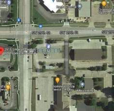

You can also read