Analysis of the Displacement of Thin-Walled Workpiece Using a High-Speed Camera during Peripheral Milling of Aluminum Alloys
←
→
Page content transcription
If your browser does not render page correctly, please read the page content below
materials
Article
Analysis of the Displacement of Thin-Walled Workpiece Using
a High-Speed Camera during Peripheral Milling of
Aluminum Alloys
Jakub Czyżycki *, Paweł Twardowski                     and Natalia Znojkiewicz

                                          Faculty of Mechanical Engineering, Poznan University of Technology, ul. Piotrowo 3, 60-965 Poznan, Poland;
                                          pawel.twardowski@put.poznan.pl (P.T.); natalia.w.znojkiewicz@doctorate.put.poznan.pl (N.Z.)
                                          * Correspondence: jakub.r.czyzycki@doctorate.put.poznan.pl

                                          Abstract: The paper presents the possibilities of a high-speed camera in recording displacements of
                                          thin-walled workpiece during milling made of aluminum alloys, which allowed for an analysis in
                                          which it was compared to other methods of testing the deflection of such elements. The tests were
                                          carried out during peripheral milling with constant cutting parameters. Deflection of thin-walled
                                          workpiece due to cutting forces was measured using a high-speed camera and a laser displacement
                                          sensor. Additionally, the experimental results were compared with the theoretical results obtained
                                          with the use of the finite element method. The research proved the effectiveness of the use of high-
                                          speed camera in diagnostics of thin-walled workpieces during milling with an accuracy of up to 11%
                                          compared to measurements made with a displacement laser sensor.


                                          Keywords: milling; deformation; thin-walled workpiece; aluminum alloys; high-speed camera
Citation: Czyżycki, J.; Twardowski,
P.; Znojkiewicz, N. Analysis of the
Displacement of Thin-Walled
Workpiece Using a High-Speed
Camera during Peripheral Milling of
                                          1. Introduction
Aluminum Alloys. Materials 2021, 14,            Thin-walled constructions are increasingly used in various fields of industry, allowing
4771. https://doi.org/10.3390/            to obtain monolithic structures that eliminate the need to perform assembly operations
ma14164771                                from multiple components. The advantages that give the ability to create structures made
                                          of thin-walled parts are difficulties in their implementation related to deformation under
Academic Editors: Thomas Niendorf         the influence of cutting forces resulting in deterioration of the surface quality, permanent
and S. Joseph Poon                        deformation of the element and difficulties or impossibility to assemble [1–3].
                                                The use of HSM (high-speed machining) allows for the simultaneous reduction of the
Received: 20 July 2021
                                          cutting force components, which is very important when machining thin-walled work-
Accepted: 20 August 2021
                                          pieces, minimizing their deformation and at the same time obtaining a good quality
Published: 23 August 2021
                                          of the treated surface. In addition, this treatment on the example of Bałoń et al. tests
                                          gives the possibility of reducing the machining time four times compared to conventional
Publisher’s Note: MDPI stays neutral
                                          machining [2,4].
with regard to jurisdictional claims in
                                                A number of studies focus on predicting the behavior of thin-walled workpieces
published maps and institutional affil-
                                          during cutting through finite element studies or on the basis of general mathematical
iations.
                                          models or those developed specifically for a given application [5,6].
                                                The authors of the study [6] focused on predicting thermal loads and deformations of a
                                          thin-walled workpiece made of aluminum alloy used in the aviation industry. Laser sensors
                                          at two measuring points were used to measure the deformation. The results obtained from
Copyright: © 2021 by the authors.
                                          the finite element analysis were compared to the experimental test, obtaining the prediction
Licensee MDPI, Basel, Switzerland.
                                          of deformations and thermal load of the tested element with an error of 15–25%.
This article is an open access article
                                                Other studies, in turn, lead to the correction of the tool path and the selection of
distributed under the terms and
                                          optimal technological parameters in order to minimize the deformation of the processed
conditions of the Creative Commons
Attribution (CC BY) license (https://
                                          materialand the possibility of chatter [7–10].
creativecommons.org/licenses/by/
                                                As described earlier, the formation of chatter during the machining of thin-walled
4.0/).
                                          workpieces has a very negative impact on the quality of their surface. In order to minimize

Materials 2021, 14, 4771. https://doi.org/10.3390/ma14164771                                               https://www.mdpi.com/journal/materials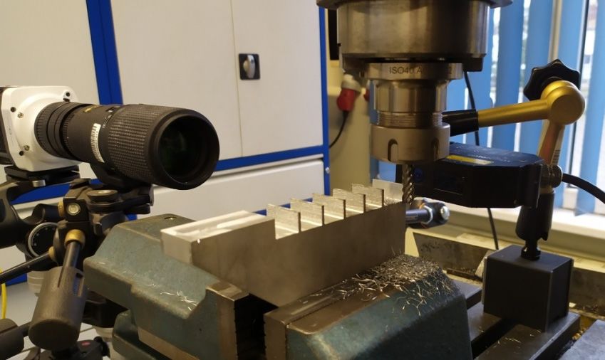
Materials 2021, 14, 4771                                                                                           2 of 12

                           this risk, the authors [11] focus on the study of the natural frequency of thin walls with
                           their various dimensional variants with the use of an automatic ball launcher. The results
                           obtained using this method do not differ from the traditional method of measurement
                           with the use of a modal hammer, additionally they were compared to analytical methods
                           (including FEM). The biggest advantage of this method is the possibility of its implementa-
                           tion in industry when machining thin-walled workpieces in order to control the possibility
                           of self-excited vibrations formation.
                                 The research [7] made it possible to reduce the flatness deviation of the milled element
                           by 45% by obtaining an optimized tool path by predicting the deflection of a thin-walled
                           workpiece using the finite element method. Similarly, Soori and Asmael [10] presented
                           the results of the tool path optimization based on the developed algorithm based on the
                           finite element method and the analytical model. Compensation allowed them to reduce
                           deformations by half.
                                 One of the methods of reducing the deformation of thin workpieces during their
                           processing is the use of special machining fixtures or supporting them (these methods
                           arenot always possible), nevertheless, they themselves can be the cause of post-machining
                           deformations after removing the clamping forces [1,12,13]. Zha et al. [14] avoided the need
                           to use additional supports and fixtures when milling thin-walled workpieces made of
                           titanium alloys by selecting an appropriate machining strategy. Semi-finishing machining
                           with large depths of cut and after that finishing next step with the previouos layer allowed
                           them to shorten the machining time by 40% while maintaining the required quality of the
                           processed surface.
                                 High-speed cameras are currently used in machining to a small extent, they are mainly
                           used in the diagnostics of machine tools to measure the accuracy of positioning [15], tool
                           displacement [16] and in the field of material strength [17–19].
                                 High-speed cameras available on the market that allow for recording in a large number
                           of frames per second, while maintaining the resolution that allows to register changes in
                           the cutting process, cost tens of thousands of dollars, the authors [20] have developed
                           a high-speed camera, the cost of which was a fraction of the amount indicated earlier.
                           The camera allowed to record in 2329 frames per second with resolution 256 × 256. By
                           increasing the possibilities of recording in a greater number of frames per second, it would
                           allow the use of such a camera in the diagnosis of machining processes.
                                 The use of a high-speed camera during the shear test allowed for the precise deter-
                           mination of the three shear stages of the tested titanium alloys [18]. On the other hand,
                           the research [21] allowed to measure temperature changes with the use of a high-speed
                           infrared camera during the perforation of ES mild steel. Kuczmaszewski et al. [22] carried
                           out a measurement of the chip temperature during drilling of a magnesium alloy in order to
                           determine the possible risk of ignition during machining. Among the tested technological
                           parameters, the depth of cut had the greatest impact on the chip temperature.
                                 In the study [23], a high-speed camera was used to analyze the morphology of chip
                           formation in the cutting process, the study was additionally confirmed with an analytical
                           model and an inconsiderable influence of the cutting speed change on the geometric
                           features of the chip. On the other hand, Guo et al. [24] presented a method of using a
                           high-speed camera to analyze the dynamics of flow, deformation fields and chip formation
                           in the process of sliding and cutting H02 bronze. The research allowed for the in situ
                           analysis of the impact angle on the chip form in the range of −70◦ to +15◦ . The use of a
                           high-speed camera and a merchant circle diagram allowed for the analysis of cutting force,
                           torque and the amount of material removed during turning. However, the obtained results
                           were not compared to the actual values mentioned by the authors [25].
                                 The authors of Rypin et al. used a high-speed camera to analyze the course of cutting
                           with a single abrasive grain in order to create a geometric model that was used to develop
                           a computer model of micro-cutting with a single abrasive grain [26].
                                 Berezvai, Bachrathy and Stepan successfully used a high-speed camera to detect the
                           formation of chatter during orthogonal cutting. In addition, this method can be effectively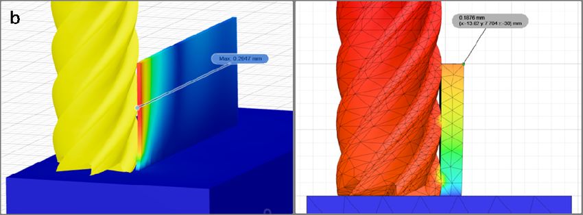
not compared to the actual values mentioned by the authors [25].
The authors of Rypin et al. used a high-speed camera to analyze the course of cutting
with a single abrasive grain in order to create a geometric model that was used to develop
a computer model of micro-cutting with a single abrasive grain [26].
Materials 2021, 14, 4771 Berezvai, Bachrathy and Stepan successfully used a high-speed camera to detect3 the of 12
formation of chatter during orthogonal cutting. In addition, this method can be effectively
used with small diameter cutters, where accelerometric measurements does not meet the
possibility of measurement. On the other hand, there is no comparison of the detection of
used with small diameter cutters, where accelerometric measurements does not meet the
chatter to other methods, for example the vibration acceleration sensor, as a method
possibility of measurement. On the other hand, there is no comparison of the detection
commonly used in this type of test [27].
of chatter to other methods, for example the vibration acceleration sensor, as a method
The aimused
commonly of the
in work is toofestimate
this type test [27].the possibility of high-speed camera in predicting
deflections of thin-walled workpiece,
The aim of the work is to estimate there
the is no literature
possibility work focusing
of high-speed on this
camera subject.
in predicting
deflections of thin-walled workpiece, there is no literature work focusing on this subject.
2. Materials and Methods
2. Materials
2.1. and
Material and Methods Parameters
Technological
2.1. Machining
Material andofTechnological Parameters
thin walls made of 7075 aluminum alloys was carried out on an AVIA
FND 32 Machining
tool milling of thin walls (factory
machine made ofof 7075 aluminum
precision alloys
machine wasAvia,
tools carried out on an
Warsaw, AVIA
Poland)
FNDa32
with toolcarbide
solid milling end machine
mill (factory
(FRAISAofC15589391)
precision machine tools Avia,
with a diameter ofWarsaw,
D = 8 mm, Poland)
the
with a solid
number carbide
of teeth z = 6,end
toolmill (FRAISA
helix angle λC15589391) withtoa the
s = 40° adapted diameter of Dof=aluminum
finishing 8 mm, the number
alloys.
The initialz =
of teeth 6, tool
wall helix angle
thickness = 40◦the
t was λ2smm, adapted to theand
wall height finishing
hence ofthealuminum alloys.
cutting depth ap =The
10
initial
mm, thewall
cutting widtht being
thickness was 2 the
mm,thickness
the wall ofheight and hence
the layer of thethecutcutting
materialdepth ap =a 10
during mm,
single
the cutting
pass was ae =width
0.2 mm, being
thethe thicknesswas
machining of the layerout
carried of the cut cutting
at the materialspeed
duringvc=a110
single pass
m/min
was a
for feed = 0.2 mm, the machining was carried out at the cutting
e per tooth fz = 0.02 mm/tooth. The technological parameters were speed v = 110 m/min
c selected on the for
feed per tooth f
basis of Fraisa companyz = 0.02 mm/tooth. The technological parameters were
recommendations for processing with the selected tool for theselected on the
basis of being
material Fraisaprocessed
company and recommendations for processing
the possible parameters to be with the selected
implemented toolmilling
on the for the
materialused.
machine being processed and the possible parameters to be implemented on the milling
machine used.
2.2. Thin-Walled Workpiece
2.2. Thin-Walled Workpiece
Figure 1 shows a schematic of a thin-walled workpiece that was the subject of the
Figure 1 shows a schematic of a thin-walled workpiece that was the subject of the
study. The initial wall thickness was 2 mm with a height of 10 mm. The thickness of the
study. The initial wall thickness was 2 mm with a height of 10 mm. The thickness of the
milled walls was realized in the range of 2–0.5 mm, which at a height of 10 mm gives the
milled walls was realized in the range of 2–0.5 mm, which at a height of 10 mm gives the
ratio of height to thickness corresponding to thin-walled parts used in industry [4,5,7].
ratio of height to thickness corresponding to thin-walled parts used in industry [4,5,7].
Figure
Figure1.1.Research
Researchsample
samplecontaining
containingthin
thinwalls.
walls.
2.3.Experimental
2.3. ExperimentalSetup
Setup
Thediagram
The diagrambelow
below(Figure
(Figure2)2)shows
showsthe
theexperimental
experimentalsetup,
setup,the
thePhantom
Phantommiro
mirom310
m310
high-speed camera (Vision Research, Wayne, NJ, USA) and the Micro-Epsilon
high-speed camera (Vision Research, Wayne, NJ, USA) and the Micro-Epsilon optoNCDToptoNCDT
ILD1700-10LL
ILD1700-10 LLdisplacement
displacementlaser
lasersensor
sensor(Micro-Epsilon
(Micro-Epsilon,,Ortenburg,
Ortenburg,Germany)
Germany)with
withan
an
accuracy of 0.5 µm were used to test the deflection of thin walls. The wall deflection was
accuracy of 0.5 µm were used to test the deflection of thin walls. The wall deflection was
analyzed at the moment when the end mill exited the last stage of cutting the assumed
analyzed at the moment when the end mill exited the last stage of cutting the assumed
cutting layer. Tema Motion computer software allowed to obtain the course of thin wall
cutting layer. Tema Motion computer software allowed to obtain the course of thin wall
deflection by analyzing the position of the marked point (wall corner) during machining.
deflection by analyzing the position of the marked point (wall corner) during machining.
Figure 3 shows a photo of the test stand. The high-speed camera recorded the image in
384 × 288 resolution at 16,000 frames per second.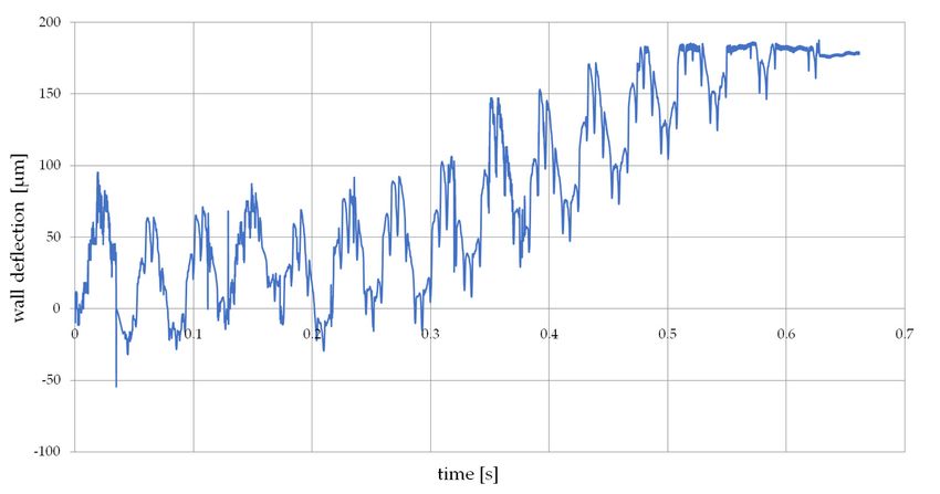
Materials
Materials 2021,
2021, 14,
14, xx FOR
FOR PEER
PEER REVIEW
REVIEW 44 of
of 12
12
Materials 2021, 14, 4771 4 of 12
Figure
Figure 33 shows
shows aa photo
photo of
of the
the test
test stand.
stand. The
The high-speed
high-speed camera
camera recorded
recorded the
the image
image in
in
384
384 ×× 288
288 resolution
resolution at
at 16,000
16,000 frames
frames per
per second.
second.
Figure2.
Figure 2. Experimental
Experimental setup.
setup.
Figure 3.
Figure3.
Figure Photo
3. Photo of
Photo of test
of test stand.
test stand.
stand.
3.
3. Results
Results
Figure
Figure44shows
Figure showsan
shows an example
exampleof
example ofaa frame
frame fromfrom aa film
film recorded
recordedwith
recorded withaa high-speed
with high-speedcamera
high-speed camera
camera
while
while milling
while milling aaa thin
milling thin wall.
thin wall. The
wall. The measurement
The measurement
measurement point point was
point waswas marked
marked in
marked in the
in the form
the form of
form of the
of the left
the left
left
corner,
corner, the
the position
position of
of which
which was
was monitored
monitored during
during the
the
corner, the position of which was monitored during the recording. The recorded sample recording.
recording. The
The recorded
recorded sample
sample
waveform
waveformis
waveform isshown
is shownin
shown inFigure
in Figure5.
Figure 5.The
5. Thegraph
The graphshows
graph showsthe
shows themoment
the momentwhen
moment whenthe
when thecutter
the cutterexited
cutter exitedthe
exited the
the
machined
machined
machined wall. wall.
wall.
The
Thefollowing
The followingtest
following testresults
test resultsshow
results show
show thethe
themaximum
maximum
maximum elastic deflection
elastic
elastic deflection
deflectionof aof
ofthin wallwall
aa thin
thin at itsat
wall attop
its
its
at
top the
top at stage
at the
the stageof completing
stage of of completing a single
completing aa single end
single endmill pass
end mill by
mill pass cutting
pass by a
by cutting given material
cutting aa given
given material thickness
material thickness and
thickness
reaching
and
and reaching up to up
reaching 180to
up µm.
to 180
180This
µm.
µm. value
Thisisvalue
This of great
value is importance
is of
of great because itbecause
great importance
importance allows toititdetermine
because allows
allows to to
whether
determine the
determine whether deformation
whether the is large
the deformation
deformation isenough to
is large reduce
large enough
enough to the assumed
to reduce
reduce the cutting
the assumed
assumed layer (ae ), which
cutting
cutting layer
layer
will
(a cause
whichan
(aee),), which will
willerror
cause
causein anthe thickness
an error
error in theofthickness
in the the wall of
thickness being
of the made,
the wall as proven
wall being
being made,in
made, asthe
as tests.in
proven
proven inThethe
the
analyzed
tests. recordings and deformations obtained from laser sensor confirm the absence of
tests. The The analyzed
analyzed recordings
recordings and and deformations
deformations obtained
obtained from from laser
laser sensor
sensor confirm
confirm the the
plastic
absence deformation in the entire thickness range of the milled thin-walled workpiece [28].
absence of of plastic
plastic deformation
deformation in in the
the entire
entire thickness
thickness rangerange of of the
the milled
milled thin-walled
thin-walled
The diagram below (Figure 6) shows an example of measuring the deformation of a
workpiece
workpiece [28]. [28].
machined thin wall with the use of a laser displacement sensor. The plot shows the moment
The
The diagram
diagram belowbelow (Figure
(Figure 6) 6) shows
shows an an example
example of of measuring
measuring the the deformation
deformation of of aa
when the cutter approaches the measurement point, where the deformation reaches its
machined
machined thin thin wall
wall withwith thethe use
use of of aa laser
laser displacement
displacement sensor. sensor. The
The plot plot shows
shows the the
maximum value, and then the deformation disappears with the moment when the tool
moment
moment when when the the cutter
cutter approaches
approaches the the measurement
measurement point, point, where
where the the deformation
deformation
loses contact with the machined wall. This confirms the absence of plastic deformation.
reaches
reaches its its maximum
maximum value, value, andand then
then thethe deformation
deformation disappears
disappears withwith thethe moment
moment when when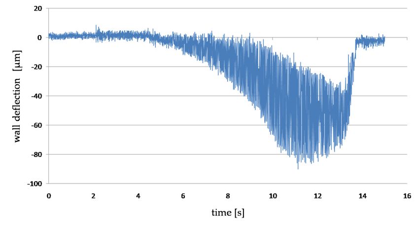
Materials
Materials2021,
2021,14,
14,xxFOR
FORPEER
PEERREVIEW
REVIEW 55 of
of 12
12
Materials 2021, 14, 4771 5 of 12
the
the tool
tool loses
loses contact
contact with
with the
the machined
machined wall.
wall. This
This confirms
confirms the
the absence
absence of
of plastic
plastic
deformation.
deformation.
Figure
Figure4.4.
Figure 4.AAAframe
frameof
frame film
ofof
film recorded
filmrecordedwith
with
recorded aahigh-speed
high-speed
with camera
camera
a high-speed while
whilemilling
camera aathin
thinwall.
millingmilling
while wall.
a thin wall.
Materials 2021, 14, x FOR PEER REVIEW
Figure
Figure5.5.
Figure 5.The
Theplot
The plotof
plot the
ofof deflection
the
the of
deflection
deflection ofthe
of thin-walled
thethe workpiece
thin-walled
thin-walled obtained
workpiece
workpiece on
onthe
obtained
obtained basis
on
the the of
basis 6 re-
ofthe
basis
the of
of 12 recording
re-the
cording
cordinganalysis.
analysis.analysis.
Theplot
Figure6.6.The
Figure plotofofthe
thedeflection
deflectionofofthe
the thin-walled
thin-walledworkpiece
workpieceobtained
obtainedbybymeasuring
measuringthe
the deforma-
tion with awith
deformation displacement laserlaser
a displacement sensor.
sensor.
Figure 7 shows the dependence of the influence of wall thickness t on the deflection
during milling, measured simultaneously with a displacement laser sensor and a high-
speed camera. Both characteristics weresimilar to each other in the entire range of the
thickness of the cut walls. Below 1 mm of wall thickness, a sharp increase in deformation
of up to 200 µm at a thickness of t 0.4 mm couldbe observed. Measurement of thin wall
deformations allowed for an accuracy of up to 11% compared to the displacement laser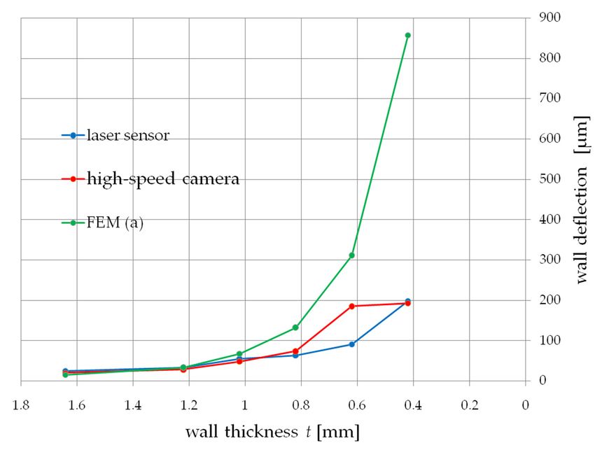
Materials 2021, 14, 4771 Figure 6. The plot of the deflection of the thin-walled workpiece obtained by measuring
6 ofthe
12
deformation with a displacement laser sensor.
Figure 7 shows the dependence of the influence of wall thickness t on the deflection
Figure
during 7 shows
milling, the dependence
measured of thewith
simultaneously influence of wall thickness
a displacement t on the
laser sensor deflection
and a high-
speed camera. Both characteristics weresimilar to each other in the entire rangeaofhigh-
during milling, measured simultaneously with a displacement laser sensor and the
speed camera.
thickness of the Both characteristics
cut walls. Below 1 mm weresimilar to each a
of wall thickness, other
sharpinincrease
the entire
in range of the
deformation
thickness
of of the
up to 200 µmcut
at awalls. Below
thickness of1t mm
0.4 mmof wall thickness,
couldbe a sharp
observed. increase in deformation
Measurement of thin wall
of up to 200 µm at a thickness of t 0.4 mm couldbe observed.
deformations allowed for an accuracy of up to 11% compared to the Measurement
displacement of laser
thin
wall deformations allowed for an accuracy of up to 11% compared to the displacement
sensor.
laser sensor.
Materials 2021, 14, x FOR PEER REVIEW 7 of 12
Figure 7. Comparison of the results of the measurement of deflection during thin-wall milling
Figure 7. Comparison of the results of the measurement of deflection during thin-wall milling
measured with a laser displacement sensor and a high-speed camera.
measured with a laser displacement sensor and a high-speed camera.
harmonicAdditionally, the Tema Motion
values, these basic software enabled the on amplitude-frequency analysis
Additionally, the werethe
Tema Motion signals
software depending
enabled the the kinematics of the process
amplitude-frequency analysis
of the
milling. displacement of the machined wall from the recording made using FFT (Figure 8).
of the displacement of the machined wall from the recording made using FFT (Figure 8).
There weretwo
Asweretwo basic
presented dependencies
in dependencies on
the research [21], it:
There basic on it: this method can be successfully used in the
• fo —frequency
detection of chatters,related
whichto inthe spindlehas
particular speed n, fo impact
a large = n/60,when machining thin-walled
•• ffo—frequency
—frequency related
of the to the spindle
milling process speed
f = fn,×fo z.
= n/60,
workpieces.
oz oz o
• foz—frequency of the milling process foz = fo × z.
In all analyzed spectra of displacement of milled walls, the greatest amplitudes
occurred for the signal component with the frequency fo ≈ 23.33 Hz depending on the
spindle rotational speed, then foz ≈ 140 Hz frequency of the milling process and their
Anexample
Figure8.8.An
Figure exampleofofthe
theamplitude-frequency
amplitude-frequencyanalysis
analysisofofthe
thedisplacement
displacementofofthe
themilled
milledwall.
wall.
In all analyzed spectra of displacement of milled walls, the greatest amplitudes oc-
In order to broaden the possibilities of predicting the deflection of thin walls during
curred for the signal component with the frequency fo ≈ 23.33 Hz depending on the spindle
milling, the finite element method (FEM) implemented in the Fusion 360 program was
rotational speed, then foz ≈ 140 Hz frequency of the milling process and their harmonic
used. Two attempts of the deflection analysis using this method were carried out. In the
values, these werethe basic signals depending on the kinematics of the process milling.
first (a), the wall was loaded with a constant force of 100 N obtained on the basis of
measurements carried out in previous tests with machining with identical cutting
conditions. The second attempt (b) consisted in applying pressure to the wall with a
modeled tool (end mill) equal to the thickness of the cutting layer. This method more
accurately represents the actual milling process in which, at a small thickness of the
cutting layer (ae), the contact of the cutter with the machined wall is at the points where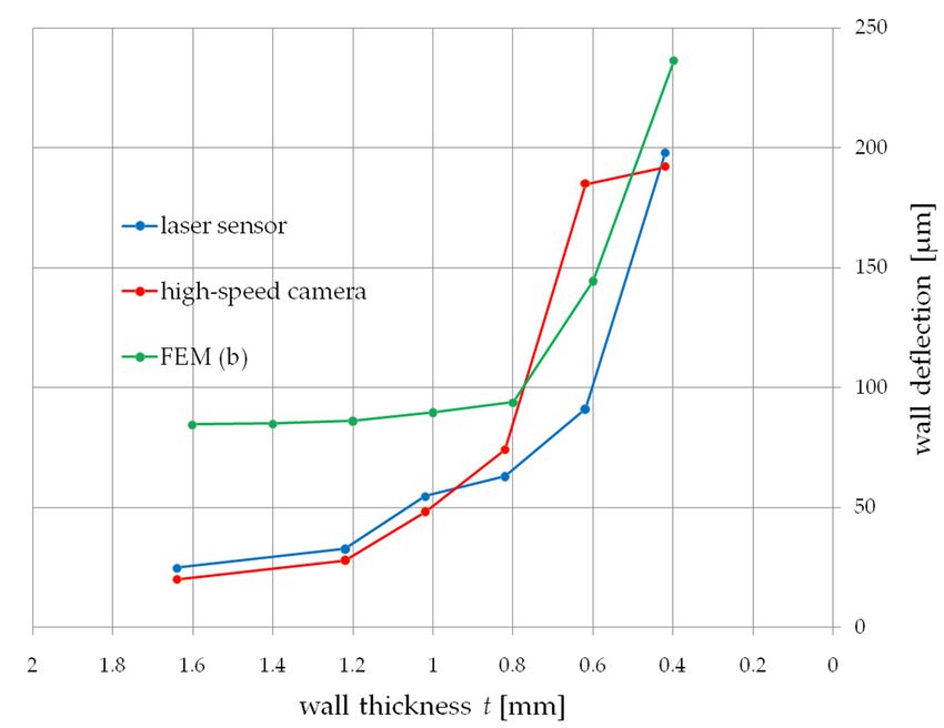
Materials 2021, 14, 4771                                                                                                                           7 of 12

                                                 As presented in the research [21], this method can be successfully used in the detection
                                           of chatters, which in particular has a large impact when machining thin-walled workpieces.
                                                 In order to broaden the possibilities of predicting the deflection of thin walls during
                                           milling, the finite element method (FEM) implemented in the Fusion 360 program was used.
                                           Two attempts of the deflection analysis using this method were carried out. In the first (a),
                                           the wall was loaded with a constant force of 100 N obtained on the basis of measurements
                                           carried out in previous tests with machining with identical cutting conditions. The second
                                           attempt (b) consisted in applying pressure to the wall with a modeled tool (end mill) equal
                                           to the thickness of the cutting layer. This method more accurately represents the actual
                                           milling process in which, at a small thickness of the cutting layer (ae ), the contact of the
               Materials 2021, 14, x FOR PEER REVIEW                                                                    8 of 13
                                           cutter with the machined wall is at the points where the cutter blades are      in contact at a
                                           given moment. Figure 9 shows the simulation of both trials.

      Figure 9. Thin wall deflection simulation made in Fusion 360: (a) constant force 100 N; (b) pressure of the end mill on the
      thin wall.

                                        The values of deflections obtained on the basis of the simulation allowed to obtain two
                                   courses presented below (Figures 10 and 11). Both tests a and b did not allow to predict the
                                   deflection of the tested wall in the full range of its thickness. The continuous load showed
                                   the deflection compliance within the range of 1 mm of the wall thickness, while the action
                                   of theFigure
                                          cutter9. on
                                                   Thinthe
                                                        wallwall    correctly
                                                              deflection         showed
                                                                         simulation made inthe    deflection
                                                                                             Fusion             for thickness
                                                                                                    360: (a) constant              values
                                                                                                                      force 100 N; (b)       t above 1 mm.
                                                                                                                                       pressure
                                        Aofnumber
                                           the end millofonstudies
                                                            the thin wall.
                                                                       using the finite element method to predict thin wall deflections
                                   focus on one     variant of a workpiece with a constant thickness, where the selection of the
                                               The values of deflections obtained on the basis of the simulation allowed to obtain
                                   load method
                                         two coursesin presented
                                                        the simulation       is simplified.
                                                                    below (Figures   10 and 11).The
                                                                                                  Bothvariable
                                                                                                        tests a anddeflection      characteristics
                                                                                                                      b did not allow   to pre-      of the
                                   wall at  different
                                         dict             thicknesses
                                              the deflection   of the testedmake
                                                                             wall initthe
                                                                                        difficult
                                                                                          full rangeto
                                                                                                     of predict    deflection
                                                                                                        its thickness.             usingload
                                                                                                                        The continuous      the presented
                                         showed
                                   methods         the deflection
                                              in this   study. compliance within the range of 1 mm of the wall thickness, while
                                          the action of the cutter on the wall correctly showed the deflection for thickness values t
                                          above 1 mm.
                                               A number of studies using the finite element method to predict thin wall deflections
                                          focus on one variant of a workpiece with a constant thickness, where the selection of the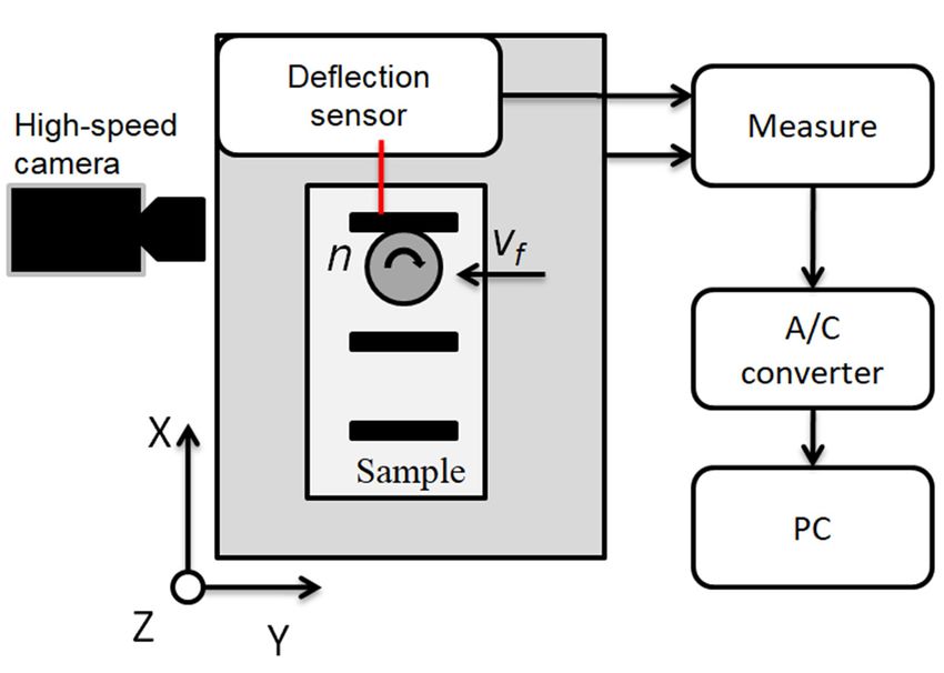
while the
                           values        action
                                   t above       of the cutter on the wall correctly showed the deflection for thickness
                                             1 mm.
                            values  t above   1  mm.
                                 A number of studies using the finite element method to predict thin wall deflections
                           focusAonnumber      of studies
                                       one variant         using the finite
                                                      of a workpiece  with aelement
                                                                               constantmethod   to predict
                                                                                         thickness,  wherethin
                                                                                                            the wall  deflections
                                                                                                                 selection of the
                            focus on   one  variant   of a workpiece   with  a constant   thickness, where   the selection
                           load method in the simulation is simplified. The variable deflection characteristics of         of the
                                                                                                                               the
Materials 2021, 14, 4771    load method     in  the simulation  is simplified.  The   variable deflection  characteristics
                           wall at different thicknesses make it difficult to predict deflection using the presented       of8 the
                                                                                                                               of 12
                            wall at   different
                           methods in this study. thicknesses  make   it difficult to  predict deflection  using   the presented
                            methods in this study.

                           Figure 10. Finite element analysis—wall deflection under the influence of a constant force, test a.
                            Figure10.
                           Figure       Finiteelement
                                   10.Finite   elementanalysis—wall
                                                       analysis—walldeflection
                                                                     deflectionunder
                                                                                underthe
                                                                                      theinfluence
                                                                                          influenceofofaaconstant
                                                                                                          constantforce,
                                                                                                                   force,test
                                                                                                                          testa.a.

                           Figure
                            Figure11.
                                   11.Finite
                                        Finiteelement
                                                elementanalysis—wall
                                                        analysis—walldeflection
                                                                      deflectionunder
                                                                                 underinfluence
                                                                                        influenceofofthe
                                                                                                      thecutter,
                                                                                                          cutter,test
                                                                                                                  testb.b.
                           Figure 11. Finite element analysis—wall deflection under influence of the cutter, test b.
                            4. Discussion
                                 The aim of the research was to verify the usefulness of a high-speed camera in record-
                            ing deformations of a thin-walled workpiece during peripheral milling. On the basis of
                            the presented results, a difference of 11–28% can be noticed compared to the displacement
                            laser sensor as the commonly used method for measuring thin elements. The error of 28%
                            is when the deformation for a wall with a thickness of 0.62 mm is taken into account, for
                            which the deformation value differs from the entire obtained plot, repeating the tests in a
                            larger number of samples will result in obtaining greater accuracy, eliminating this error, at
                            the same time, the calculation of the uncertainty of measurement is minor (Figure 12).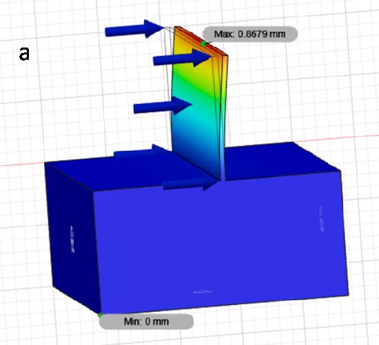
basis of the presented results, a difference of 11–28% can be noticed compared to the
displacement laser sensor as the commonly used method for measuring thin elements.
The error of 28% is when the deformation for a wall with a thickness of 0.62 mm is taken
into account, for which the deformation value differs from the entire obtained plot,
Materials 2021, 14, 4771 repeating the tests in a larger number of samples will result in obtaining greater accuracy,
9 of 12
eliminating this error, at the same time, the calculation of the uncertainty of measurement
is minor (Figure 12).
Figure 12.
Figure 12. Measurement
Measurementuncertainty
uncertaintywhen
whenmeasuring thin
measuring walled
thin workpiece
walled deflection
workpiece withwith
deflection a high-
a
speed camera
high-speed and displacement
camera laserlaser
and displacement sensor.
sensor.
In addition,
In addition, the FEM FEM simulation
simulationininboth bothvariants
variantsallows
allows to to
estimate
estimate thethedeformation
deforma-
in a way
tion in a that
wayallows for additional
that allows verification
for additional of the results
verification of theobtained
results from the high-speed
obtained from the
camera.
high-speed camera.
The method
The method of applying
applying forcesforces to toaathin
thinwall
wallisisa adifficult
difficulttopic
topicand
and is is
carried outout
carried by
many
by many researchers
researchers in aindifferent
a different way. way.TheThemethod
method of applying
of applying thetheforces depends
forces dependson onthe
the
typetype of the
of the selected
selected tooltool
and and thethe machining
machining method
method (climb
(climb oror upupmilling).
milling).Hence,
Hence, it itis
is plannedtotoconduct
conducttests testsusing
usingaatwo-edge
two-edgeend end mill
mill with the tool o
planned tool helix
helix angle
angleλλs s==00o toto
facilitate
facilitate the
the FEM
FEMsimulation.
simulation.
The
The authors
authors [6][6] obtained
obtained the the prediction
prediction of of deformations
deformations with with aa inconsiderable
inconsiderable error,
error,
but
but the
the way
way in in which
which the the force
force waswas aa applied
applied to to the treated
treated surfaces
surfaces hashas not
not been
been specified,
specified,
which
whichwould
wouldcertainly
certainlyserve serveand andfacilitate
facilitatefurther
furtherresearch.
research.
On the other
On the other hand, the tests [5], as described
tests [5], as described earlier,earlier, carried
carriedout outaasimulation
simulationinina
amanner
manner close to the actual cutting conditions, allowing for
close to the actual cutting conditions, allowing for tearing off a part of tearing off a the
partmaterial
of the
material
removedremovedfrom the from the thin-wall,
thin-wall, achieving
achieving highhigh accuracy
accuracy in in predictingthe
predicting the deformation.
deformation.
Figure
Figure11 11shows
showsthe theresults
resultsofof thethesimulation
simulation in which
in whichthethemodeled
modeled cutter plunges
cutter into into
plunges the
machined wall, unbending it. The obtained deformation values
the machined wall, unbending it. The obtained deformation values are overestimated by are overestimated by 50%
in
50%relation to thetoresults
in relation obtained
the results from from
obtained the laser displacement
the laser displacementsensor. This This
sensor. method has
method
proven successful in the range of wall thicknesses below 1 mm,
has proven successful in the range of wall thicknesses below 1 mm, which at the thickness-which at the thickness-to-
height
to-heightratioratio
is problematic
is problematic in prediction due to the change
in prediction due tointhe the dynamic
change in characteristics
the dynamic of
the wall.
characteristics of the wall.
The
The advantage
advantage of of using
using aahigh-speed
high-speedcamera cameraover
overaadisplacement
displacementlaser lasersensor
sensorisisthe
the
larger
larger spectrum of data that can be obtained from this method. A high-speed camera
spectrum of data that can be obtained from this method. A high-speed camera
allows
allows to record aa recording
to record recordingof ofthe
thecutting
cuttingprocess,
process,which
which wewe can can freely
freely analyze
analyze with
with the
the appropriate software, recording the values of deformations, deflections, perform a
appropriate software, recording the values of deformations, deflections, perform a
frequency analysis, analysis of chip formation. Additionally, analysis of cutting force,
torque and the amount of material removed. All these elements can make it possible to
minimize the measuring equipment necessary to conduct research on the cutting process
and machining of thin-walled workpieces.
Additionally, from the obtained registration of the course, we are able to determine
the occurrence of plastic deformation of the workpiece without the need to perform
meteorological measurements.
The use of a high-speed camera requires certain test conditions, such as: ensuring
adequate lighting, free space in the camera’s working space, quality and type of the tested
surface. The selection of the resolution and the number of frames per second with which
the recording will be carried out affects the length of file processing by the software and
their weight, which should also be taken into account when conducting tests. The need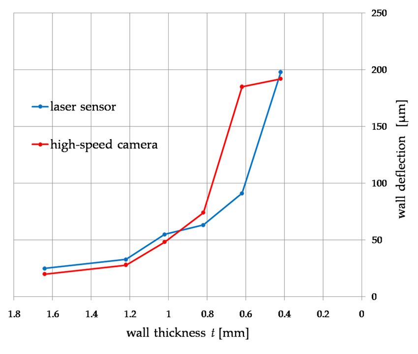
Materials 2021, 14, 4771                                                                                            10 of 12

                           to use an additional light source had a negative impact on the measurements carried out
                           by making it difficult to study the deformation of a very strongly illuminated wall with a
                           laser sensor. In addition, during machining, the cutting chips fly into the space between
                           the tested wall and the high-speed camera, causing the loss of the ability to track the
                           marked point (upper corner of the wall), which resulted in the need to manually re-set the
                           measurement point.
                                 At the present moment, on the basis of the conducted research and the analyzed
                           literature, it is difficult to identify the factors that have the greatest impact on the accuracy
                           of measurements carried out with the use of high-speed cameras. On the basis of own
                           research, a significant influence of the preparation of the side surface of the wall on the
                           accuracy of the traceability of the point defined on it by the software was found. During
                           further research, various methods of eliminating this problem will be tested by obtaining
                           a matte surface with the use of matte paint and improving the quality of the surface by
                           selecting an appropriate finishing machining when preparing the test sample.
                                 The thin walls being the subject of the study were made on a sample having a rectan-
                           gular base with smooth sides. As the research shows [11], the differences in the mounting
                           of a very similar sample with thin walls influenced in less than 5% the difference in the
                           frequency analysis, which allows for assuming no significant influence of the mounting
                           method on the results obtained in the study.
                                 The tests were carried out on a conventional AVIA FND 32 tool milling machine,
                           the maximum rotational speed of the spindle of which didnot allow achieving the recom-
                           mended cutting speed vc = 550 m/min for the selected cutter. However, the value of the
                           feed per tooth was kept to maintain the recommended cutting conditions. These differences
                           could affect the result of the deflection value, therefore further tests will be carried out on a
                           milling center with a high-speed spindle. The choice of the machine tool was dictated by
                           the large access to the working space of the tool, as shown in Figure 3, space is required in
                           a certain range parallel to the processed wall, allowing for the sharpness of the image for
                           the camera. In addition, a large part of numerically controlled machine tools has a sliding
                           table in one or two axes, causing that the camera would have to move with the table or be
                           on it in order not to lose the sharpness of the image.
                                 Further research will focus on verifying the accuracy of thin-walled workpiece de-
                           formation measurements using high-speed cameras in both aluminum and titanium alloy
                           machining. A more accurate FEM simulation method will be developed to predict the
                           deformation of thin walls in a wide range of their dimensions. The possibility of measur-
                           ing the deformation of thin elements in other places than from the front of the wall (for
                           example closed thin-walled pockets) will be tested. All this will allow for the development
                           of guidelines and instructions for the machining of thin-walled workpieces.

                           5. Conclusions
                                Based on the research, the following conclusions can be drawn:
                           •    the high-speed camera can be successfully used to test thin wall deflections during
                                milling, which is confirmed by the results compared to the measurement of displace-
                                ments with a laser sensor with an accuracy of up to 11% and simulation by the finite
                                element method with error of 22%,
                           •    notwithstanding, it should be mentioned that the measurement itself requires spe-
                                cific conditions which include many factors that may introduce an error into the
                                measurement or make it impossible,
                           •    research confirms the dependence of nonlinearities in the deformation of thin walls
                                under the influence of cutting forces, deformations below 1 mm of the wall thickness
                                increase rapidly, which was noticed in previous studies, despite a different workpiece
                                material such as hardened steel [28],
                           •    the simulation carried out with the use of the finite element method, depending on
                                the sample, made it possible to predict the deflection of thin-walled workpieces in a
                                certain range of wall thickness,
Materials 2021, 14, 4771 11 of 12
• taking into account both simulation tests with the finite element method, the results
obtained with them separately in the range of up to 1 mm of the wall thickness and
below are estimated with an error of 22%,
• examination of deflections of thin-walled workpieces with a high-speed camera allows
us to conduct a spectral analysis of their displacement, which makes it possible to
diagnose them to an even greater extent, for example, for detecting chatter.
Author Contributions: Conceptualization, J.C. and P.T.; methodology, J.C. and P.T.; software, J.C.;
formal analysis, J.C., P.T. and N.Z.; investigation, J.C., P.T. and N.Z.; resources, J.C.; writing—original
draft preparation, J.C. and P.T.; writing—review and editing, J.C., P.T. and N.Z.; visualization, J.C.;
supervision, P.T.; funding acquisition, J.C. All authors have read and agreed to the published version
of the manuscript.
Funding: The project/research was financed in the framework of the project Poznan University of
Technology a subsidy for the maintenance and development of research potential 0614/SBAD/1531.
Institutional Review Board Statement: Not applicable.
Informed Consent Statement: Not applicable.
Data Availability Statement: The data presented in this study are available on request from the
corresponding author.
Conflicts of Interest: The authors declare no conflict of interest.
References
1. Z˛ebala, W. Errors minimalisation of thin-walled parts machining. Inż. Maszyn 2010, 3, 45–54. (In Polish)
2. Bałon, P.; Rejman, E.; Smusz, R.; Kiełbasa, B. High Speed Machining of the Thin-Walled Aircraft Constructions. Mechanik 2017, 90,
726–729. [CrossRef]
3. Zhang, Z.; Qi, Y.; Cheng, Q.; Liu, Z.; Tao, Z.; Cai, L. Machining Accuracy Reliability during the Peripheral Milling Process of
Thin-Walled Components. Robot. Comput. Integr. Manuf. 2019, 59, 222–234. [CrossRef]
4. Bałon, P.; Rejman, E.; Światoniowski,
˛ A.; Kiełbasa, B.; Smusz, R.; Szostak, J.; Cieślik, J.; Kowalski, Ł. Thin-Walled Integral
Constructions in Aircraft Industry. Procedia Manuf. 2020, 47, 498–504. [CrossRef]
5. Izamshah, R.A.; John, P.T.M.; Ding, S.L. Finite Element Analysis of Machining Thin-Wall Parts. Key Eng. Mater. 2010, 458, 283–288.
[CrossRef]
6. Hussain, A.; Lazoglu, I. Distortion in Milling of Structural Parts. CIRP Ann. 2019, 68, 105–108. [CrossRef]
7. Polzer, A.; Dufkova, K.; Pokorny, P. On the modern CNC milling with a compensation of cutting tools and thin-walled workpiece
deflections. J. Mach. Eng. 2015, 15, 41–49. [CrossRef]
8. Rubeo, M.A.; Schmitz, T.L. Global Stability Predictions for Flexible Workpiece Milling Using Time Domain Simulation. J. Manuf.
Syst. 2016, 40, 8–14. [CrossRef]
9. Li, Z.-L.; Zhu, L.-M. Compensation of Deformation Errors in Five-Axis Flank Milling of Thin-Walled Parts via Tool Path
Optimization. Precis. Eng. 2019, 55, 77–87. [CrossRef]
10. Soori, M.; Asmael, M. Deflection Error Prediction and Minimization in 5-Axis Milling Operations of Thin-Walled Impeller
Blades. 2020. Available online: https://assets.researchsquare.com/files/rs-87233/v1_stamped.pdf?c=1602255123 (accessed on 18
July 2021).
11. Bachrathy, D.; Kiss, A.K.; Kossa, A.; Berezvai, S.; Hajdu, D.; Stepan, G. In-Process Monitoring of Changing Dynamics of a
Thin-Walled Component During Milling Operation by Ball Shooter Excitation. JMMP 2020, 4, 78. [CrossRef]
12. Zawada-Michałowska, M.; Kuczmaszewski, J.; Pieśko, P. Pre-Machining of Rolled Plates as an Element of Minimising the
Post-Machining Deformations. Materials 2020, 13, 4777. [CrossRef]
13. Singh, A.; Agrawal, A. Comparison of Deforming Forces, Residual Stresses and Geometrical Accuracy of Deformation Machining
with Conventional Bending and Forming. J. Mater. Process. Technol. 2016, 234, 259–271. [CrossRef]
14. Zha, J.; Liang, J.; Li, Y.; Zhang, H.; Chen, Y. Large Cutting Depth and Layered Milling of Titanium Alloy Thin-Walled Parts.
Materials 2020, 13, 1499. [CrossRef]
15. Struzikiewicz, G.; Sioma, A. Application of Infrared and High-Speed Cameras in Diagnostics of CNC Milling Machines: Case
Study. In Photonics Applications in Astronomy, Communications, Industry, and High-Energy Physics Experiments; Romaniuk, R.S.,
Linczuk, M., Eds.; SPIE: Wilga, Poland, 2019; p. 69. [CrossRef]
16. Leopardi, G.; Tagliaferri, F.; Rüger, C.; Dix, M. Analysis of Laser Assisted Milling (LAM) of Inconel 718 with Ceramic Tools.
Procedia CIRP 2015, 33, 514–519. [CrossRef]
17. Ran, C.; Chen, P. Dynamic Shear Deformation and Failure of Ti-6Al-4V and Ti-5Al-5Mo-5V-1Cr-1Fe Alloys. Materials 2018, 11, 76.
[CrossRef]Materials 2021, 14, 4771 12 of 12
18. Żaba, K.; Trzepieciński, T.; Puchlerska, S.; Noga, P.; Balcerzak, M. Coupled Thermomechanical Response Measurement of
Deformation of Nickel-Based Superalloys Using Full-Field Digital Image Correlation and Infrared Thermography. Materials 2021,
14, 2163. [CrossRef] [PubMed]
19. Agirre, J.; Otegi, N.; Abedul, D.; Oruna, A.; Galdos, L. Monitoring of a Hammer Forging Testing Machine for High-Speed Material
Characterization. Procedia Manuf. 2020, 47, 321–328. [CrossRef]
20. Chalich, Y.; Mallick, A.; Gupta, B.; Deen, M.J. Development of a Low-Cost, User-Customizable, High-Speed Camera. PLoS ONE
2020, 15, e0232788. [CrossRef]
21. Rodríguez-Martínez, J.A.; Rusinek, A.; Chevrier, P.; Bernier, R.; Arias, A. Temperature Measurements on ES Steel Sheets Subjected
to Perforation by Hemispherical Projectiles. Int. J. Impact Eng. 2010, 37, 828–841. [CrossRef]
22. Kuczmaszewski, J.; Zagórski, I.; Zgórniak, P. Thermographic Study of Chip Temperature in High-Speed Dry Milling Magnesium
Alloys. Manag. Prod. Eng. Rev. 2016, 7, 86–92. [CrossRef]
23. Sutter, G.; Molinari, A.; List, G.; Bi, X. Chip Flow and Scaling Laws in High Speed Metal Cutting. J. Manuf. Sci. Eng. 2012,
134, 021005. [CrossRef]
24. Guo, Y.; Compton, W.D.; Chandrasekar, S. In Situ Analysis of Flow Dynamics and Deformation Fields in Cutting and Sliding of
Metals. Proc. R. Soc. A 2015, 471, 20150194. [CrossRef]
25. Polishetty, A.; Littlefair, G.; Tumma, S. Materials Machining Study of Titanium Alloy Using a High Speed Camera. Key Eng. Mater.
2016, 723, 171–176. [CrossRef]
26. Rypina, Ł.; Lipiński, D.; Bałasz, B.; Kacalak, W.; Szatkiewicz, T. Analysis and Modeling of the Micro-Cutting Process of Ti-6Al-4V
Titanium Alloy with Single Abrasive Grain. Materials 2020, 13, 5835. [CrossRef] [PubMed]
27. Berezvai, S.; Bachrathy, D.; Stepan, G. High-Speed Camera Measurements in the Mechanical Analysis of Machining. Procedia
CIRP 2018, 77, 155–158. [CrossRef]
28. Czyżycki, J.; Twardowski, P. Evaluation of Deflection of Thin-Walled Profile During Milling of Hardened Steel. In Industrial
Measurements in Machining; Królczyk, G.M., Niesłony, P., Królczyk, J., Eds.; Lecture Notes in Mechanical Engineering; Springer:
Cham, Switzerland, 2020; pp. 22–32. [CrossRef]You can also read