Indoor Navigation-User Requirements, State-of-the-Art and Developments for Smartphone Localization
←
→
Page content transcription
If your browser does not render page correctly, please read the page content below
Review
Indoor Navigation—User Requirements, State-of-the-Art and
Developments for Smartphone Localization
Günther Retscher

                                         Department of Geodesy and Geoinformation, TU Wien—Vienna University of Technology, 1040 Vienna, Austria;
                                         guenther.retscher@tuwien.ac.at

                                         Abstract: A variety of positioning systems have emerged for indoor localization which are based on
                                         several system strategies, location methods, and technologies while using different signals, such as
                                         radio frequency (RF) signals. Demands regarding positioning in terms of performance, robustness,
                                         availability and positioning accuracies are increasing. The overall goal of indoor positioning is to
                                         provide GNSS-like functionality in places where GNSS signals are not available. Analysis of the
                                         state-of-the-art indicates that although a lot of work is being done to combine both the outdoor and
                                         indoor positioning systems, there are still many problems and challenges to be solved. Most people
                                         moving on the city streets and interiors of public facilities have a smartphone, and most professionals
                                         working in public facilities or construction sites are equipped with tablets or smartphone devices.
                                         If users already have the necessary equipment, they should be provided with further functionalities
                                         that will help them in day-to-day life and work. In this review study, user requirements and the
                                         state-of-the-art in system development for smartphone localization are discussed. In particular,
                                         localization with current and upcoming ‘signals-of-opportunity’ (SoP) for use in mobile devices is the
                                         main focus of this paper.

                                         Keywords: smartphone positioning; indoor environment; user requirements; key performance
                                         indicators; challenges; signals-of-opportunity (SoP); inertial navigation systems (INS); MEMS-based
                                         sensors; wireless Fidelity (Wi-Fi); Ultra-wide Band (UWB); smartphone camera

Citation: Retscher, G. Indoor
                                         1. Introduction
Navigation—User Requirements,
State-of-the-Art and Developments
                                              Indoor positioning, localisation and navigation are gaining more attention in society,
for Smartphone Localization.             industry and business. To date, the positioning systems were mainly based on satellite
Geomatics 2023, 3, 1–46. https://        observations with Global Navigation Satellite Systems (GNSS) that cannot be used inside
doi.org/10.3390/geomatics3010001         the buildings. With the increasing ubiquity of smartphones and other mobile devices, users
                                         are now routinely carrying a variety of sensors with them wherever they go. These devices
Academic Editor: Naser El-Sheimy
                                         are enabling technologies for ubiquitous computing, facilitating continuous updates of
Received: 25 August 2022                 a user’s context [1]. Cell phones can nowadays receive signals from multi-constellation
Revised: 7 December 2022                 GNSS satellites on two frequency bands (L1 and L5 in the case of the US Navstar Global
Accepted: 21 December 2022               Positioning System GPS; see, e.g., [2,3]) as well as dual-band Wi-Fi on 2.4 and 5 GHz.
Published: 27 December 2022              Such technologies are predesignated to be used in Location-based Services (LBS). Moreover,
                                         it can be expected that simple tasks of applied surveying can be performed with smart-
                                         phones in the near future. This saves time and cost, since no additional hardware has to be
                                         purchased as the smartphone is a constant companion anyway. In order to investigate to
Copyright: © 2022 by the authors.
                                         what extent smartphones are suitable for measurement tasks, the accuracy to be achieved,
Licensee MDPI, Basel, Switzerland.
This article is an open access article
                                         the measurement effort, the repeatability of the measurement results and the quality of
distributed under the terms and
                                         the measurement data are of particular interest. In this paper, especially their usage for
conditions of the Creative Commons
                                         positioning in indoor and GNSS challenged and denied environments is investigated.
Attribution (CC BY) license (https://         Starting from a book chapter on ‘Indoor Navigation’ written by the author and pub-
creativecommons.org/licenses/by/         lished in the Encyclopedia of Geodesy in 2016 [4] this paper provides an update on the
4.0/).

Geomatics 2023, 3, 1–46. https://doi.org/10.3390/geomatics3010001                                      https://www.mdpi.com/journal/geomatics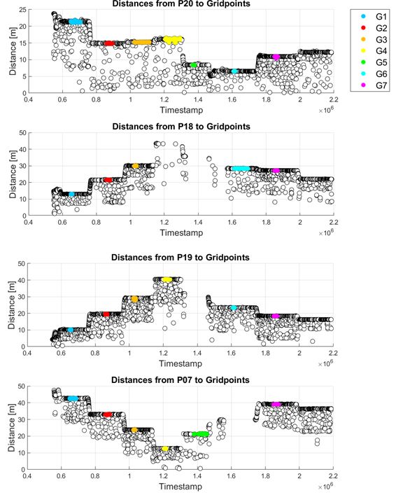
Geomatics 2023, 3                                                                                                         2

                    current state-of-the-art and advances in indoor navigation. In this introductory book chap-
                    ter a comprehensive and concise overview about technologies and techniques which can be
                    employed for indoor positioning and navigation is provided. Indoor navigation is defined
                    in this work as:
                         Indoor positioning is defined as any system which attempts to provide an accurate
                         positioning inside of a covered structure using radio waves, acoustic signals, or other
                         sensory information collected by mobile devices. It is primarily used for real-time location
                         of people or objects in large buildings and in closed areas/spaces. Several types of location-
                         sensing systems exist in which each have its own strengths and limitations.
                          Based on a classification of Li and Rizos [5] in the Editorial of the Journal of Location
                    Based Services in 2014 for a special issue of the International Conference on Indoor Posi-
                    tioning and Navigation (IPIN) 2012, the following differentiation of indoor localization
                    technologies and techniques was made. These authors have identified three classes in
                    indoor navigation, i.e., (1) designated technologies based on pre-deployed signal trans-
                    mission infrastructure, (2) technologies based on so-called ‘signals-of-opportunity’ (SoP),
                    and (3) technologies not based on signals. Infrastructure-based technologies started with the
                    development of systems using infrared (see, e.g., [6]) or ultrasonic signals (see, e.g., [7,8]),
                    followed by the usage of geomagnetic and/or induced magnetic fields [9], Bluetooth Low
                    Energy (BLE), Wireless Fidelity (Wi-Fi), Zigbee, Radio Frequency Identification (RFID),
                    Ultra-wide Band (UWB), or other RF-based (radio frequency based) systems. These wire-
                    less technologies are under rapid development also in relation to smartphone localization.
                    Types of wireless technologies being developed range from simple IrDA that uses infrared
                    light for short-range, point-to-point communications, to wireless personal area network
                    (WPAN) for short-range, point-to-multi-point communications, such as Bluetooth and
                    ZigBee, to mid-range, multi-hop wireless local area network (WLAN or usually referred to
                    as Wi-Fi in the case of positioning), to long-distance cellular phone systems, such as 5G [1].
                    Thereby the most commonly employed SoP is the usage of Wi-Fi for localization [10]. Apart
                    from Wi-Fi, also mobile telephony, FM radio, digital television, and others are SoP [5].
                    The third category includes mainly sensors for relative positioning providing continuous
                    localization from a given start position using techniques such as dead reckoning (DR).
                    The most usable sensors of this kind embedded into smartphones or other mobile devices
                    are accelerometers and gyroscopes based on MEMS (Micro-electro Mechanical System)
                    technology. With these very low-cost sensors inertial navigation can be carried out; that is
                    why they are referred to as inertial sensors (INS) [11]. In addition, an embedded magne-
                    tometer or digital compass in the mobile device can be employed for determination of
                    the direction or heading of the user. Moreover, barometric pressure sensors are found in
                    smartphones enabling altitude determination together with temperature sensors, such as
                    to estimate the correct floor in a multi-storey building where the user is currently located.
                    In addition, vision/camera systems belong also to the third category employing scene
                    analysis and visual odometry [12].
                          Figure 1 summarizes the main technologies and techniques for indoor and outdoor
                    relative or absolute positioning and Figure 2 visualizes their state of maturity and adoption.
                    The 2018 edition of the GNSS User Technology Reports [13] published every year by the
                    European Union Agency for the Space Programme (EUSPA) served as a main source for
                    this overview and summary. In 2022, EUSPA published the first edition of a joint EO (Earth
                    Observation) and GNSS Market Report [14] which provides further information. As can be
                    seen from these two Figures, the technologies and techniques vary depending on the used
                    signals and sensors.
                          In a second book chapter co-authored by the author of this article entitled ‘Naviga-
                    tion Based on Sensors in Smartphones’ [11] especially the use of sensors based on MEMS
                    technology together with an integration with wireless options in smartphones is elabo-
                    rated. Furthermore, several review type papers from the literature summarizing types of
                    sensors and technologies for indoor navigation, such as [8,15,16], are building the basis for
                    preparation of this article.
Geomatics 2023, 3                                                                                                    3

                    Figure 1. Main technologies and techniques for indoor and outdoor relative or absolute positioning
                    of smartphones (excerpt from [13]).

                    Figure 2. The PNT ecosystem indicating the state of maturity and adoption of the different sensors,
                    technologies and techniques (This figure is updated from the one in [13]).
Geomatics 2023, 3                                                                                                    4

                         The paper is organized as follows: In Section 2, the user requirements with their key
                    performance parameters are discussed followed by the description of the main localization
                    topologies and methods in Section 3. Section 4 is dedicated to inertial navigation (IN)
                    where a change in philosophy is proposed to use the IN sensors as the primary localiza-
                    tion technique which is updated by absolute localization technologies and techniques to
                    encounter for the IN sensor errors and drifts. This is followed by Section 5 where the
                    combination of sensors and techniques is discussed. Thereby an emphasis is led on the
                    use of radio frequency (RF) based wireless techniques (Section 5.1). Section 6 identifies
                    the main smartphone-based localization capabilities and describes their usage in modern
                    indoor navigation systems. A comparison of systems is then provided in Section 7 arranged
                    in three Tables. Finally, concluding remarks are given in Section 8.

                    2. User Requirements
                         If someone talks about localization in general, the user requirements for a certain type
                    of application need to be considered and defined. In this section, the key performance
                    parameters derived from GNSS positioning are identified based on the directive of the
                    GNSS User Technology Report [13] and their relationship is discussed. One very important
                    parameter thereby is the integrity of the solution as indicated in Section 2.3.

                    2.1. Key Performance Parameters
                         In the GNSS User Technology Report from 2018 [13] also the main four dimensions of
                    PNT (Positioning, Navigation and Timing) systems technology development that enable
                    the future of automated intelligent positioning systems are presented. These are apart from
                    positioning accuracy and ubiquity also security and connectivity building the fundament
                    visualized in a PNT technology drivers pyramid as shown in Figure 3. Thus, the core
                    statement in [13] is that reliable and robust location systems must be ubiquitous, secure, ac-
                    curate and connected to provide the basis for modern automation and ambient intelligence.
                    The following descriptions are given in the report:
                    •    Accuracy is obtained thanks to multi constellation, multi-frequency GNSS, augmented
                         by PPP-RTK (Precise Point Positioning – Real Time Kinematic) services and hybridized
                         with INS and other sensors;
                    •    Connectivity relies on the integration with both satellites and terrestrial networks,
                         such as the mobile 5G networks, LEO (Low Earth Orbit) satellites or LPWANs (Low
                         Power Wide Area Networks);
                    •    Ubiquity is provided by complementary positioning technologies and sensors; and
                    •    Security is provided by the combination of independent redundant technologies,
                         cybersecurity and authentication.
                          To achieve the goal of continuous navigation in mixed (transition) environments,
                    such as open areas, partially obstructed, and indoors requires the fusion of multiple
                    positioning technologies and sensors. Then ubiquitous navigation is achievable which
                    requires the usage of multi-sensor, low-cost and robust navigation solutions.
                          In 2022, in the first published combined edition of the EO (Earth Observation) and
                    GNSS Market Report [14], the definitions of the key parameters for navigation are stated
                    more precisely. Annex 2 of the report provides the definitions and characteristics. The most
                    important parameters which are applicable for any type of PNT are: (1) availability; (2) ac-
                    curacy; (3) continuity; (4) integrity; (5) robustness; (6) authentication and (7) time-to-first-fix
                    (TTFF). These key parameters have been defined comprehensively in the report. Table 1
                    provides an overview of these key performance parameters and their priorities for mass
                    market solutions and safety and liability critical applications. Other performance parame-
                    ters are also given which are especially relevant if smartphones or other low- cost devices
                    are used. These parameters are: (1) power consumption; (2) resiliency; (3) connectivity;
                    (4) interoperability and (5) traceability.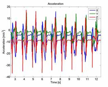
Geomatics 2023, 3                                                                                              5

                    Figure 3. PNT drivers pyramid (after [13]).

                          In the author’s opinion these key performance parameters are relevant and have to be
                    applied to any type of localization solution and technology. As presented at the FIG Work-
                    ing Week in 2020 [17], the parameters apply to any PNT applications not involving only
                    GNSS but also other sensors and technologies which are additionally and independently
                    used. In the following, examples are given. For instance, in Wi-Fi or UWB positioning
                    similar key requirements and performance parameters can be formulated and applied.
                    In the case of availability, the number of stationary transmitters (UWB stationary units or
                    Wi-Fi Access Points) plays a similar role to the number of GNSS satellites. They stationary
                    units are thereby referred to as infrastructure nodes or anchors and their placement is also
                    decisive is the current location of the satellites if one thinks about geometry effects on
                    positioning accuracy. TTFF in the case of Wi-Fi signal strength-based positioning is highly
                    correlated with the RSSI (Received Signal Strength indicator) scan duration of a certain mo-
                    bile device. This is especially important in kinematic positioning. As seen in experiments of
                    the author [18], the RSSI scan durations can vary significantly for different smartphones or
                    other mobile devices resulting in significantly different achievable positioning accuracies.
                    In the case of pedestrian navigation, the result depends thereby decisively on the user’s
                    walking speed. For different users robustness may have a different meaning, such as the
                    ability of the solution to respond following a serious shadowing event. Here, robustness
                    is defined as the ability of the solution to mitigate interference. Especially integrity is
                    often neglected and not paid full attention. Section 2.3 is dedicated to this important key
                    parameter. An important performance parameter is also power consumption, especially in
                    the case of mobile devices power consumption is still very critical to provide a long-term
                    solution possibility. For solutions where ranges are derived from travel time measurements,
                    for instance, continuous measurements are very power consuming. The ability to prepare
                    for and adapt to changing conditions as described by the parameter resiliency has to be
                    considered in addition. For instance, signal strength variations and fluctuations such as it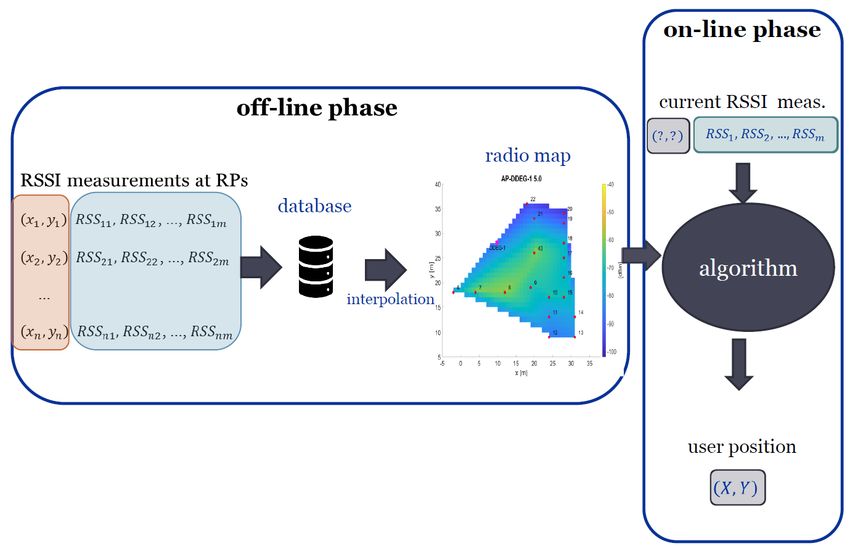
Geomatics 2023, 3                                                                                                                                                                                       6

                    is the case for Wi-Fi RSSI-based positioning have a significant impact on the positioning
                    result. To encounter for their influence new robust schemes are necessary and need to
                    be developed.

                    2.2. Positioning Requirements
                          Table 1 provides an overview about the key performance parameters and their pri-
                    orities for mass market solutions and safety and liability critical applications whereas
                    Table 2 highlights them for lower and higher performance applications. As can be seen
                    the requirements are quite different and therefore different priorities must be considered
                    and applied depending on the type of application. It can be very substantial and critical to
                    decided on the key parameters which have to be achieved in any case for the application
                    in mind [17].

                    Table 1. Key performance parameters and their priorities with low (L), medium (M) and high (H)
                    priority (after [19]).

                                                                                                                                                                                    Power Consumption
                                                                                                                                           Indoor Penetration
                                                                                                                            Robustness
                                                                     Availability

                                                                                               Continuity
                                                                                    Accuracy

                                                                                                            Integrity

                                                                                                                                                                          Latency
                                                                                                                                                                   TTFF
                     Application

                     Mass market                                     H              H          H            M               H              H                       H       L         H
                     Safety and liability critical applications      H              H          H            H               H              L                       H      H         M

                    Table 2. Requirements for lower and higher performance applications in mass market applications
                    (after [19]).

                        Performance Level                            Low                                                                                        High
                                                                                                                          Augmented Reality (AR),
                                                             Navigation, sports,
                                                                                                                          mHealth, geo marketing
                                                        tracking, social networking,
                            Application                                                                                    and advertising,fraud
                                                           enterprise applications,
                                                                                                                          management and billing,
                                                            infotainment, games
                                                                                                                           safety and emergency
                                                                                                                                           Accuracy
                                                                  Availability                                                           Authentication
                         Key requirements                                                                                                 Availability
                                                                    TTFF
                                                                                                                                             TTFF
                                                       Connectivity (incl. short range)                                 Connectivity (incl. short range)
                        Other requirements                   Interoperability                                                 Interoperability
                                                           Power consumption                                                Power consumption

                         Thus, maintaining overall performance requires the fusion of multiple positioning
                    technologies and sensors. GNSS only solutions are difficult or even impossible, for instance,
                    in urban canyons or non-line-of-sight (NLoS) conditions leading to multipath effects and a
                    reduction of the number of satellites in view. The gap in satellite coverage or GNSS perfor-
                    mance is not acceptable for many applications and is addressed by using complementary
                    technologies (compare their state of maturity and adoption in Figure 2). The different
                    technologies differ quite significantly with respect to their state of maturity. Especially,
                    signals-of-opportunity (SoP) have to be highlighted because their usage are one of the
                    great opportunities for future ubiquitous user localization in any environment. Automated
                    systems have progressed very rapidly recently thanks to the development alongside all
                    four dimensions of the PNT drivers pyramid base (Figure 3). The main aims in any type of
                    application are therefore to deliver GNSS-like performance anywhere, anytime, under any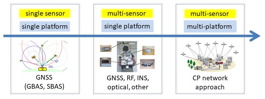
Geomatics 2023, 3                                                                                                     7

                    operating conditions as well as to exceed the performance levels of GNSS for safety and
                    liability critical applications.

                    2.3. The Key Parameter Integrity
                         According to [20] integrity is the most important performance metric from the point
                    of safety. To recall, integrity is mainly defined as the ability of the positioning system to
                    provide warnings to users when it should not be used. Gabela et al. [21] define the integrity
                    of the positioning system solution as a measure of trust one can put in the value of the
                    estimated position [22–24]. Thus, integrity means ‘a guarantee of safety’ practically [25].
                    As it is stated in [21], ‘a guarantee of safety’, however, cannot be given without any risk
                    of misleading information associated with it. This risk exists due to the different error
                    sources of the positioning system, such as the signal errors in GNSS positioning that affect
                    the measurement system and need to be limited to a specified tolerable level that differs
                    depending on the application.
                         The integrity has become relevant in addition to the development of robust positioning
                    systems, to support the further development of any localization system. The way that
                    integrity is ensured and assessed, and the means of delivering integrity related information
                    to the user are highly application dependent. It can be distinguished between integrity
                    monitoring and position integrity. The definitions are given as follows:
                    •    Integrity monitoring is the ability of a system to provide timely warnings to users
                         when the system should not be used for navigation [26]; and
                    •    Position integrity is the general performance feature referring to the level of trust a user
                         can have in the value of a given position or velocity as provided by a location system [22].
                          Integrity monitoring was first used in civil aviation [20,26,27] and has now become a
                    key performance metric for developing more robust integrity monitoring algorithms for
                    applications in GNSS-challenged/denied environments [24,28]. Integrity parameters are
                    threefold, i.e., (1) the integrity risk IR; (2) the alarm limit AL; and (3) the protection level PL.
                    Figure 4 shows the integrity parameters PL and AL and their relationship to an estimated
                    positioning solution and the ground truth. The IR is the probability that, at any moment in
                    a certain reference time interval, the position error (PE) exceeds a confidence interval. That
                    confidence interval can be called PL. The PL can be defined as a ‘radius of an interval (of a
                    circle in a plane), with its centre being at the true position, which describes the region which
                    is assured to contain the estimated quantity’ with probability 1 − IR. It means that the
                    estimated position solution (by the positioning system) is bounded by the PL (estimated by
                    the integrity algorithm) with the probability of 1 − IR. AL, on the other hand, is a radius of
                    an interval (of a circle in a plane), with its centre being at the true position, which describes
                    the region which is required to contain the indicated position with a probability 1 − IR.

                    Figure 4. The integrity parameters and their relationship to an estimated positioning solution and
                    the ground truth (i.e., true position) (This Figure was made similar as in [29]).

                    2.4. Relationship between Key Parameters
                          The relationship between the key parameters accuracy, integrity, continuity and avail-
                    ability is depicted in Figure 5. From bottom to top the relationship between all four
                    parameters is shown. The relationships start from accuracy to integrity followed by con-
                    tinuity and availability. They are crucial for any kind of development in the PNT field.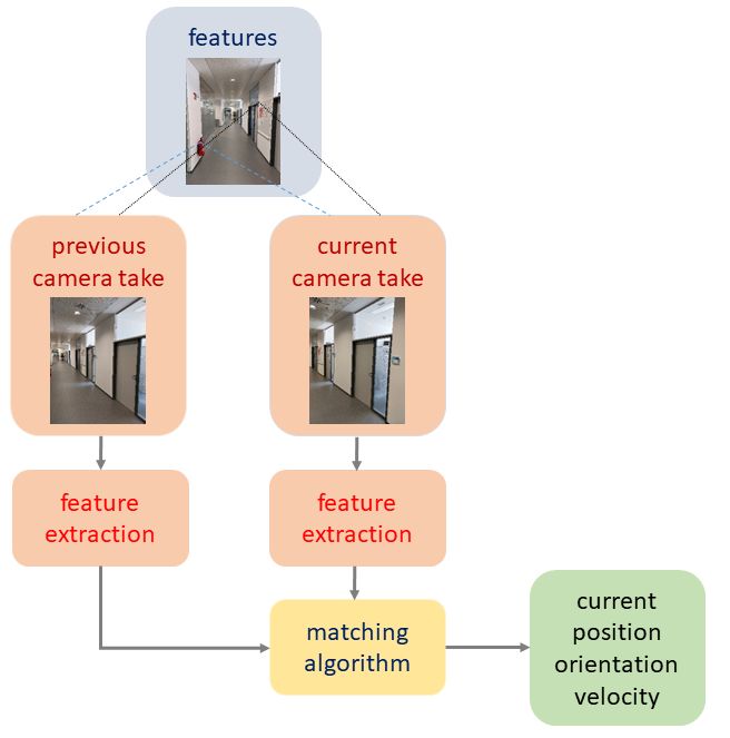
Geomatics 2023, 3                                                                                                    8

                    As aforementioned, integrity has become relevant in addition to the development of ro-
                    bust positioning systems, to support further development in PNT. As can be seen from
                    Figure 5, the integrity parameter is directly linked to continuity and availability similar
                    as accuracy. Moreover, a system has to provide continuous localization capabilities and
                    a high availability [29].

                    Figure 5. Relationships between the key parameters accuracy, integrity, continuity and availability
                    for PNT systems.

                         If one looks back to the PNT technologies drivers pyramid in Figure 3 the most impor-
                    tant key points are identified for PNT challenges and their possible solutions. Together with
                    the key parameters identified it will be possible to develop robust positioning solutions.
                    This requires, however, the fusion of multiple positioning technologies and sensors for
                    maintaining performance in all contexts.

                    3. Localization Topologies and Methods
                          Apart from positioning and tracking as well as absolute and relative positioning, phys-
                    ical or geometrical and symbolic localization are distinguished when referring to common
                    localization methods [8]. The description of a certain location with coordinates that identify
                    a location on a map is the most typical example of geometrical localization. Providing an
                    address and/or using landmarks in positioning and navigation symbolic localization is
                    applied. Moreover, four different location system topologies are distinguishable; they are
                    based on self- and remote-positioning. In the first self-positioning topology, a mobile station
                    (MS) or device uses measurements from outside transmitters which are placed at known
                    locations to locate itself. Two forms are commonly employed depending on the situation
                    where the location is calculated, either in the mobile device or in a network, such as a cell
                    phone network. This is referred to as MS-based for the first self-positioning topology and
                    MS-assisted for the latter. Remote-positioning concerns the topology where measurements
                    are carried out in a network. In this case, the mobile unit serves as a signal transmitter
                    and several fixed stations at known coordinates are measured. For both topologies, either
                    direct or indirect positioning is distinguished in dependence on where the measurements
                    and position calculations take place. The MS-based approach is described by direct self-
                    positioning as both the measurements and the position estimation are carried out in the
                    mobile unit. The MS-assisted approach is indirect remote-positioning as the measurements
                    are taken in the mobile unit but the calculation of the position is performed, e.g., on a central
                    server in the network. Indirect self-positioning means, on the other hand, the topology
                    that the measurements made in the network are sent via a data link to the mobile unit
                    which estimates its position. Direct remote-positioning is then in consequence the topology
                    involving the measurements and position estimation central on a network server.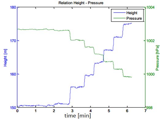
Geomatics 2023, 3                                                                                                  9

                         Moreover, localization can be classified into cell-based positioning, proximity tech-
                    nique, (tri/multi)lateration and angulation, hyperbolic lateration, scene analysis, location
                    fingerprinting, dead reckoning (DR) and hybrid solutions. The author provides a compre-
                    hensive overview of these techniques applied to indoor localization in [4]. In the following,
                    only the principles of the most relevant methods for the localization of smartphones are
                    briefly discussed and new developments are highlighted.

                    3.1. Cell-Based Positioning
                         The cell-based approach – referred to as cell-ID (identification) or cell-of-origin (CoO)—is
                    the simplest and most straightforward method. It is based on the cell identity and the
                    location associated with it [30,31]. The location of a smartphone, for instance, is described
                    in relation to the vicinity to the location of the known object(s), such as cell towers
                    (Base transceiving stations BTS) in a cellular phone network, Wi-Fi APs (Section 5.1.1)
                    or Bluetooth tags or iBEacons (Section 5.1.2), define the location of the known object or
                    the symbolic cell-ID. Obviously the size of the associated cell results in the achievable
                    positioning accuracies [32].

                    3.2. Lateration
                         Lateration uses range measurements to known locations similar as in conventional
                    surveying. Using the intersection of at least three spherical surfaces where the centers are
                    the known locations and the radii the measured ranges the users’ location can be estimated.
                    Depending on the number of measured ranges, tri- and multilateration can be distinguished.
                    To obtain a range either one- or two-way travel times between the unknown and known
                    position are measured. The former is also referred to as time-of-arrival (ToA) or time-of-
                    flight (ToF) and the latter as a round trip time of flight (RToF) or short round trip time
                    (RTT) [8]. Wi-Fi RTT is an example for this approach; see Section 5.1.1 for further details
                         As an alternative to direct measurement of travel times, ranges to known locations can
                    also be derived from signal strength measurements. A typical example is RSSI-based Wi-Fi
                    positioning. Theoretically, the RSSI decreases with the transmitted energy propagating into
                    space. Path loss models, such as modelling the propagation on the logarithmic scale, can be
                    employed to establish the relationship between the RSSI and propagating distances [32].
                    The relationship can be defined as given in Equation (1):

                                                                          P[mW]
                                                     P[dBm] = 10 ∗ log(         )                                (1)
                                                                          1[mW]

                    where P is the transmission power, which is emitted by a transmitter., such as a Wi-Fi
                    AP, given in the logarithmic unit decibel-milliwatt (dBm). The unit Bel is a logarithmic
                    quantity and is defined by reference to a certain value. For dBm the reference value is
                    1 milliwatt (mW) which corresponds to 0 dBm. Thereby values above 1 mW result in
                    positive dBm values, values below 1 mW result in negative dBm values. The transmission
                    power of a Wi-Fi AP depends, among other things, on the frequency band on which the
                    signal is transmitted [10].
                         A simple path loss model is the so-called one-slope model which can be described as
                    given in Equation (2) [33]:

                                                     P(d) = P0 + 10 ∗ γ ∗ log(d)                                 (2)

                         This one-slop model is a very simple empiric model based on the principle of free
                    space loss of the signals. The damping factor γ depends thereby only on the logarith-
                    mic distance d between the transmitter and receiver. P is the received empirical RSSI,
                    P0 the reference RSSI in distance of 1 m.
                         Further refinements, applicable especially for indoor environments, can be made by
                    applying a modelling of walls between the user and transmitter or even by using ray
Geomatics 2023, 3 10
launching and ray tracing. For the first, the so-called multi-wall model is a straightforward
realization. It is given by the following form:
n
P(d)rec = P0 + 10 ∗ γ ∗ log(d) + ∑ Di (3)
i =1
with the additional parameter Di which is the damping value of the i-th wall. Prec is the
received RSSI. As in the one-slope model the other parameters can be determined with
a least-squares adjustment in a practical scenario by means of measured RSSI values.
It is a semi-empiric model which means in this context that the current surroundings are
incorporated in the signal propagation estimation model. Simply speaking it can be said
that the model considers the damping characteristics of existing walls between transmitter
and receiver whereby the direct path between them is treated. More realistic results than in
the one-slop model are achievable although the limitations of the multi-wall model are soon
reached if small structures, such as corridors, columns, narrow staircases, etc., and different
materials in the walls exist.
Alternatives are ray launching and ray tracing which are deterministic and ray-optical
propagation models. They model the physical propagation laws (absorption, diffraction
and reflection) on the basis of objects. Processing power, however, can be very high if a
large number of objects in the path are considered. In ray launching, on the one hand,
all isotropic rays from a transmitter and their resultant signal strengths are modelled and
calculated whereas in ray tracing, on the other hand, the possible rays to the transmitter are
determined reverse from the receiver to calculate afterwards the energy loss. To achieve
acceptable results with these models, however, the physical properties of the objects need
to be known accurately. Physical changes of the environment – as simple as opening doors
or windows—and the presence of people, however, cause an uncertainty for modelling of
the ray propagation [33].
With a differential approach for Wi-Fi positioning developed by the author [33,34] the
impact of spatial and temporal signal variations on the result are reduced. This approach
was termed Differential Wi-Fi (DWi-Fi) in analogy to the well-known Differential GPS
(DGPS or DGNSS) operational principle. Instead of theoretical path loss models continuous
RSSI scans carried out at reference stations are utilized. With these measurements then
the positioning accuracy and reliability of the user can be improved. Wi-Fi scanners as
reference stations may be collocated with APs and serve the purpose to derive range
corrections in a network. Low-cost computers, such as Raspberry Pi units, are used in this
approach to operate simultaneously as both APs and reference stations. They emit and scan
Wi-Fi signals at the same time. The result is that DWi-Fi outperforms common RSSI-based
lateration methods in complex environments.
3.3. Hyperbolic Lateration
If distance differences are measured the lines-of-position (LOPs) are hyperbolas.
In other words, the resulting hyperbolas of measurements between two transmitters are
lines of constant distance difference with each transmitter, such as a base tranceiving station
(BTS) in a cellular network, located in one of its foci. To obtain a unique 2D position
fix, measurements to at least three transmitters or receivers are necessary, or additional
information such as the approximate position needs to be known. The technology is also
referred to as a measurement of the time difference of arrival (TDoA). Further information
about hyperbolic lateration may be found in [4].
3.4. Location Fingerprinting
Location fingerprinting, however, is the most commonly applied technique when
it comes to RSSI-based localization techniques using pattern recognition [8]. It can be
considered as feature-based positioning technique as a spatially varying feature, in this
case the RSSI, is used for user localization. Fingerprinting always includes two phases,Geomatics 2023, 3 11
i.e., the off-line training phase and the on-line positioning phase. Figure 6 illustrates this
two phases.
Figure 6. The two phases of location fingerprinting.
The estimation of the users’ location can be based either on deterministic and proba-
bilistic approaches [8]. Deterministic location estimation is based on the similarity of the
RSSI measurements and the fingerprints in a database of RSSI fingerprints. Each RSSI
sample is not used separately, but the sample averages of different transmitters are collected
into a vector and used to estimate the mobile device’s location [35]. A vector distance
between the database entries and the currently measured RSSI value is estimated for local-
ization. Here most commonly the Euclidean vector distance d is selected (see, e.g., [36–39].
The vector distance d can be given by:
r
i j i,j
d( f map , f obs ) = Σnj=1 ( f obs − f map )2 (4)
where f obs is the observed fingerprint and f map the respective fingerprint in the fingerprint
radio map. The RSSI distributions in the database are visualized in so-called radio maps
indicating the RSSI values for a certain AP (compare Figure 6). The vector distance d
i
between the observed fingerprint f obs and the fingerprint in the radio map f map is calculated
and then the position with the shortest distance in the radio map, i.e., the nearest neighbour
(NN), yields the unknown location:
i
X NN = arg min d( f map , f obs ) (5)
In this NN algorithm then the Euclidean distance d is calculated for each AP in the
positioning phase from the database entries. The distance can be described by the given
mathematical relationship in Equation (4). If more neighbours with a small distance are
found next to the location to be determined they are considered for the estimation of the
location, the K-nearest neighbour (KNN) or the weighted K-nearest neighbour (WKNN)
algorithm can then be applied. In this case, K reference points (RP) in the RSSI distribution
in the fingerprint database are compared to the observed measurements to select K RPs with
the nearest RSSI values. The value K larger than 2 can be an arbitrarily selected number
or can be determined by a threshold value for a certain minimum distance. In this KNNGeomatics 2023, 3 12
approach, the location of the user is usually the centre of gravity of the K positions X NN,j
with the K-smallest vector distances [10]:
1 K
K ∑
XKNN = ∗ X NN,j (6)
j
This KNN approach can still be optimized by calculating a weighting for each K fin-
gerprint, on the basis of which the centre of gravity of all K fingerprints can be estimated as
the location of the smartphone user, i.e., the WKNN approach. An empirical determination
of K values revealed that no significant improvement of the mean deviations from the
ground truth are achieved by increasing K while measuring along waypoints of predefined
trajectories. Contrary to the expectations, the mean deviations even increased slightly
as the value of K increases over a value of 5. However, this increase was only on the
centimetre range [18].
As a suitable alternative, also machine learning algorithms, such as neural networks,
random forest, decision trees, or support vector machines (SVM), may be applied in
deterministic fingerprinting [40]. Figuera et al. [41] provide a good overview and discussion
of neural networks and SVM algorithms for Wi-Fi positioning. They found, however,
that commonly employed learning algorithms do not significantly outperform the KNN
approach in most cases. They achieved an improvement of the performance of the employed
SVM algorithm only if a priori information within the learning machine, such as using the
spectral information of the training data set, and a complex output taking into account
the advantage of the cross information in the two dimensions of the location, is used in
addition. A higher performance improvement for fingerprinting is mainly only achievable
if probabilistic approaches for positioning are employed. Two selected approaches are
presented in the following.
Usually in probabilistic approaches [42] the sample of measurements collected during
the training phase are exploited more efficiently. The conditional probability density
function (PDF) of the unknown position is calculated in the approach. Thereby the prior
distribution is usually considered to be uniform. Using Bayes’ theorem (see, e.g., [43]) and
the measurements, the posterior PDF can be estimated. The fingerprints contain information
about the signal characteristics across the cells. Then the normalized histogram pattern
measured at the reference point from a transmitter can be interpreted as the distribution of
the RSSI sample from the transmitter. Several approaches for the calculation are available,
e.g., the histogram method and the kernel method (see [36,42]). On the other hand, a simple
relationship can be derived using the Mahalanobis distance as given in Equation (7):
d M ( f map
i i
, f obs ) = ( f obs − f map )T ∗ C−
ff
1 i
∗ ( f obs − f map ) (7)
map,i
where C −
ff
1
is the empirical covariance matrix of the number of RSSIs.
map,i
In the case where the covariance matrix C −
ff
1
is the unit matrix, the Mahalanobis
map,i
distance given in Equation (7) therefore corresponds to the Euclidean distance used in the
deterministic fingerprinting approach (see Equation (4)). As the inverse of the covariance
matrix is the weight matrix, the weighted square sum of the RSSI differences between off-
line training and on-line positioning phase is calculated to obtain the Mahalanobis distance.
Thereby the weights are inversely proportional to the variances of the corresponding
fingerprints. A large number of studies have shown that probabilistic fingerprinting offers
higher accuracy than the deterministic approaches in indoor positioning, as they take better
account of signal fluctuations. Leb and Retscher [44] showed that in kinematic positioning
where the pedestrian user walked with normal step speed positioning accuracies of 2 m
on average are achievable while using the Mahalanobis distance. This type of accuracy is
comparable with commonly employed algorithms. Further details can be found in [10].
A particle filter (see, e.g., [45]), for instance, can then be used for localization.Geomatics 2023, 3 13
In [46], experiments are presented where the probabilistic fingerprinting approach
based on Mahalanobis distance was applied for localization using Wi-Fi in a University
library. As an example, Figure 7 shows the estimated vector distances in the unit dBm for
five different reference points (waypoint 1 to 5) which are located in the University library.
The horizontal axis in Figure shows the number of the waypoints along the trajectory.
As can be seen from the Figure, the positions at waypoint 1, 2, 4 and 5 have been correctly
determined in the positioning phase because the minimum of the Mahalanobis distance
is estimated at these locations. The on-line measurement in the positioning phase at
waypoint 3, however, has its minimum at point 5, which means that the position has not
been assigned correctly. This simple example demonstrates the advantages of using the
Mahalanobis vector distance for probabilistic fingerprinting. The main reason for this
result is the knowledge of the covariance matrix. whereby the standard deviations of each
fingerprint must, however, be known. The waypoint with the shortest vector distance is
then the desired location.
Figure 7. Positioning using the Mahalanobis distances at five different reference points CP01 to
CP05 which are located in the University library of TU Wien (Source: [46]).
For validating the achievable positioning performance of location fingerprinting,
the Cramér–Rao Lower Bound (CRLB) (see, e.g., [47–50]) on the Root Mean Square Error
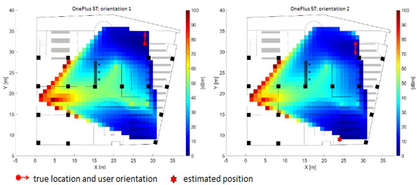
(RMSE) is applied in [46] to analyze the resulting deviations from the ground truth. Figure 8
shows a visualization of the resulting CRLB on the RMSE for the ground floor in the library
for one smartphone in two opposite user orientations. Low CRLB values in dark blue
indicate higher positioning accuracies during the on-line positioning phase, while higher
values in red mean lower accuracy. As seen from the Figure, two areas exist where the
CRLB is 2 to 3 m (green-yellow areas), while in the other parts of the area it has only values
of 0.5 to 1 m. The CRLB on the RMSE is a suitable variable for performance analysis of
localization systems in general if it is applied to errors of the positioning solution, such as
deviations of estimated locations from a ground truth.
3.5. Scene Analysis
Scene analysis is a technique where examining and matching of a video/image or
electromagnetic characteristics viewed or sensed from a target object is carried out [15].
Smartphone cameras can be used for vision-based positioning. Specific tags or significant
patters, for instance, captured in the images are then used to determine the user’s loca-
tion. Edge detection or the determination of vanishing points in the images is commonly
employed. In addition, perspective images of the environment can be compared with
pre-recorded images which are stored in a database to obtain the current location. BecauseGeomatics 2023, 3 14
of its analogy, this technique can be seen similar as location fingerprinting. During the
off-line phase images from reference points are captured to build up the database. As these
image databases require a lot of memory various features like edges, corners, blobs, ridges,
etc. are extracted from the images and stored as the database. In the on-line phase the user
captures images. Feature extraction takes then place before the matching process with the
images in the database. For this purpose often image histograms, edges, blobs, and their
spatial relationship are extracted. Thereby the selection of efficient feature extraction tech-
niques and an appropriate feature matching measure is essential for a good vision-based
localization system [16].
Figure 8. Visualization of the Cramér–Rao Lower Bound (CRLB) on the Root Mean Square Error
(RMSE) on the ground floor in the University library (Source: [46]).
If RF-signals are used it leads to location fingerprinting where a spatial variable feature,
such as the RSSI, is used (see Section 3.4). As aforementioned it was first applied in 2000 for
Wi-Fi positioning with the system RADAR [35]. Further description about Wi-Fi positioning
will follow in Section 5.1.1.
3.6. Promising Alternative Techniques
In this section, only two different promising alternative techniques for indoor local-
ization are briefly mentioned. No comprehensive discussion of all possible techniques is
carried out here, as this would be by far out of the scope of this paper.
An alternative to the aforementioned techniques are also QR codes distributed in
the area of interest, such as in a warehouse or office building. They can be detected
in images leading to localization and/or route guidance. These codes can also serve as
landmarks for symbolic localization. A simple smartphone App-based solution is presented
in [51]. Here the user has to install an App on their mobile device and as the user enters
a building all necessary information needed for navigation (maps, contact lists, etc.) are
automatically downloaded and updated. An alternative is an online solution where the
requested information is retrieved by reading an URL, which is encoded in the QR code,
using a web browser. In this case, the URL includes the address of the maps on the
external server, and an internet connection is required at all times during the visit to the
building. The advantage of this second strategy is, that the storage of the device used is
not overloaded with a large amount of data. A similar approach was implemented by TU
Wien in respect to contract tracing in the COVID-19 pandemic. Users scan the QR code at
the building entrance and are then taken to a website where their entry to the University
building is recorded in the TU Wien information system. There is a wide range of other
applications of QR codes possible. The connection to vision-based positioning will be
further discussed in Section 5.2.Geomatics 2023, 3 15
Moreover, white LEDs (light-emitting diodes) can serve as another possibility for
indoor localization. In this case, position information can be derived from a range of
properties of the received signal, such as the power of the received signal or the angle,
i.e., angle-of-arrival (AoA), at which the signal reaches the receiver [52,53]. An approach is
also the combination of ToA and AoA measurements. From the direction angles and the
distances, the location of the user can be estimated. A system developed by the BU Center
for Information and Systems Engineering called ’ByteLight’ turns LED light sources into
positioning beacons [54]. ByteLight-enabled lights transmit proprietary signals which can
be picked up by camera equipped mobile devices. Once signals are detected, the device then
calculates its position without the need for an active network connection. The manufacturer
claims that the indoor positioning solution is accurate to less than one metre and takes less
than a second to compute.
4. Inertial Navigation (IN) as Primary Sensor
Previously, INS were mostly employed to bridge gaps of GNSS positioning for a
short limited time. Thereby trajectory estimation is based usually on filtering techniques,
such as the popular Kalman filter or Extended Kalman filter [55]. Due to the high drift
causing a high error growth of INS, the period to bridge GNSS outages is very short
and a frequent updated with known absolute positions is required. This strategy of
bridging GNSS gaps can be seen as a classical approach for positioning and navigation.
In new developments a changed navigation philosophy is applied. In this case, INS is
considered as primary navigation sensor and the focus lies on bounding the INS error
growth. This approach allows a flexible and adaptive blend with other sensors, including
unconventional sensors, not designed for navigation. Here wireless technologies come into
play as they can provide absolute positioning capabilities. MEMS tri-axes accelerometers
and gyroscopes have become one of the standard features in mobile devices who enable
that the INS observations in smartphones are combined and intergraded with absolute
positions coming from Wi-Fi or other sources [11]. Research challenges in this context
include the development and application of flexible software architectures, adaptive data
filtering and sensor fusion, stochastic transition between different hybridizations as well as
the usage of intelligent algorithms, such as machine learning. Further details are provided
in the following sub-section.
4.1. INS Trajectory Estimation
The trajectory of a mobile user can be estimated from position, velocity, acceleration
and orientation measurements over time. The sensor employed is referred to as Inertial
Measurement Unit (IMU). With MEMS-based accelerometers, gyroscope, and magnetome-
ter the distance travelled as well as the direction of movement (heading or azimuth α) is
determined. GNSS and other wireless positioning techniques are then utilized to update
the estimated INS trajectory of the IMU. Thereby time synchronization of the sensors is also
an essential aspect for successful sensor fusion. Estimation theory, in general, and Kalman
filtering (see, e.g., [55–57]) in particular, provide a theoretical framework for combining
information from various sensors. By properly combining the information from an INS and
other absolute positioning systems, the errors in position and velocity are compensated for.
In the following, the operational principle of IN, dead reckoning (DR) and map matching
(MM) is briefly reviewed followed by a discussion of activity detection of pedestrian users
as well as altitude determination in indoor environments.
4.2. Inertial Navigation (IN)
IN is based on DR where from the measurement of the distance travelled and the
corresponding azimuth a position change between consecutive measurement epochs is
derived. Hence, the position, orientation, and velocity (direction and speed of movement)
of a moving user can be continuously estimated. Then the trajectory is estimated using
sequential calculation. In general, an INS consists of three orthogonal arranged motionGeomatics 2023, 3 16
sensors, i.e., accelerometers, for determination of the acceleration vector and three orthogo-
nal arranged rotation sensors, i.e., rate-gyroscopes, for attitude determination measuring
angular velocity and linear acceleration, respectively. Their observations are converted
into new observations regarding the position and orientation of the system. Six degrees
of freedom, i.e., three translations and three rotations, have to be estimated to be able to
determine a movement in space [11].
The main drawback is that IMUs suffer from integration drifts, as small errors in the
measurement of acceleration and angular velocity are integrated errors in velocity finally
leading to greater errors in position. Since the new position is calculated from the previ-
ous calculated position and the measured acceleration and angular velocity, these errors
accumulate roughly proportionally to the time. An error in the acceleration measurements
causes an error in the distance which grows squarely with time due to double integration.
Hence, the estimated position must be periodically updated by observations from absolute
positioning systems.
4.3. Dead Reckoning (DR) Principle
In DR one starts with a known location, e.g., determined by GNSS or other wireless
absolute positioning technique. Using observations of the inertial sensors then the current
position of the user can be dead reckoned by projecting the course and speed from a
known present position [58,59]. Hence, an INS can be used to make a relative position
estimate by means of DR. The current position is always calculated relative to the previously
calculated position and no correlation with the true position can be made. This process,
however, is subject to significant cumulative errors due to many factors. They are either
compounding, multiplicatively or exponentially, as both velocity and direction must be
accurately known. Any errors and uncertainties of the process are cumulative leading to
the fact that the error and uncertainty in the position grow with time [11].
In the case of pedestrian navigation, PDR (Pedestrian Dead Reckoning) is applied
to utilize the observations of the smartphone IN sensors, for instance. This operational
principle is as in DR for vehicle navigation. PDR is simply the counting of the steps and
estimation of a step length (or walking speed) as well as the course over ground (or direction
of walking). The PDR technique is effective if a hard mounting point on the pedestrian is
used. MEMS-based IMUs can be worn on the human body, such as illustrated in Figure 9.
Here optimum IMU locations are foot-mounted, such as on the shoe, or mounting on the
hips on a belt in the back of the person, for instance, if step detection (see Section 4.5) is
carried out. Still acceptable locations are holding the IMU (e.g., in the smartphone) in
the hand or have it in the trousers pocket. Thereby the IMU must be worn by the same
user since the step model is trained with a particular individual’s walking patterns [60]
otherwise a calibration for different users is required.
Figure 9. Mounting of IMU‘s on a human body.Geomatics 2023, 3 17
4.4. Map Matching (MM)
Map matching (MM) decribes the process when an estimated trajectory, e.g., obtained
via DR, of a vehicle is matched to a digital road database. Thus, MM is defined as the
technique that combines electronic map with location information to obtain the real position
of vehicles. It uses spatial road network data to determine the spatial reference of the vehicle
location [61]. The MM algorithms can be used not only to provide the vehicle’s position
in the correct road segment but also can improve the positioning accuracy if good spatial
road network data are available [62]. Different algorithms are applicable which have in
common that they use spatial information in an attempt to improve navigation accuracy.
Either the current vehicle’s location, the distance travelled or the curvature pattern of
the road elements and mutual allocation is utilized by cross correlation [63]. Cameras,
GNSS, etc., can improve positioning accuracy. For Intelligent Transportation System
(ITS) applications, however, these algorithms are mostly not yet capable of supporting
the navigation requirements [11]. High definition (HD) maps requiring centimeter-level
accuracy and ultra-high centimeter-level or higher resolution are the keys to autonomous
driving [64]. The creation of HD maps is a challenge. Currently, outdoor mobile mapping
systems equipped with high-end LiDAR, cameras, RADARs, GNSS and INS are employed
for the creation and updating of these HD maps.
In buildings, MM algorithms may employ the topology of polygons derived from the
indoor maps. Furthermore Building Information Models (BIM) can support pedestrian
navigation in an indoor environment. BIM is based on an electronic record of full knowledge
and data about a building object, and builds an intelligent 3D model-based process that
gives architecture, engineering, and construction professionals the insight and tools to more
efficiently plan, design, construct and manage buildings and infrastructure. Information
extracted from the BIM can reorganise, modify, actualise and store to facilitate access
and display model information directly on mobile devices or the Web [65,66]. With the
increasing number of smartphone users and the increase of low-cost sensors found in them,
there is an opportunity to utilize smartphones to enhance BIM technology. The sensors
and receivers found in modern smartphones can enable and improve PNT solutions for
Location-based Services (LBS). If a BIM exists also navigation in the 3D building model can
be carried out.
4.5. Activity and Step Detection
For pedestrian navigation dynamic activity and step detection are needed [67]. Human
activity recognition aims to recognize the motion of a person from a series of observations
from the user’s body and environment. For example, in [68] a single biaxial accelerometer
is employed for classifying six activities, i.e., walking, running, sitting, walking upstairs,
walking downstairs, and standing; and in [69] an activity and location recognition system
using a combination of a bi-axial accelerometer, compass, and gyroscope is used. In other
studies, sensors are also worn on the human body for activity detection [67].
When it comes to step detection usually peak detection [58,70] or zero-crossing count-
ing [60,71] on low-pass filtered accelerometer signals are used to count steps. The cycle
of walking is across a stride, i.e., two steps as can be seen in Figure 10, with typical stride
frequencies of around 1 to 2 Hz. In general, vertical acceleration provides better perfor-
mance [72], but depends on being able to isolate the orthogonal accelerations in the global
frame. This is difficult to perform on a smartphone that is not firmly attached to the body.
Instead, the signal magnitude is often substituted [73]. As an example, Figure 11 shows a
typical acceleration recording in X-, Y- and Z-axis on a smartphone. As can be seen from
the Figure, the acceleration values show significant maxima and minima. From these peaks
it is possible to count the steps of the walking user. An easy approach to count the steps
is to recognize one step from the excess of a certain threshold. Then a step is detected
when this value first gets lower than a defined threshold and subsequently upon a second
threshold. Correction for the gravity effect on the X-, Y- and Z-axes of the smartphone’s
local coordinate system is essential to correct the determination of accelerometer-derivedGeomatics 2023, 3 18
distance travelled [1]. On the other hand, zero-crossings can also be employed for step
detection. Further methods make use of the sinusoidal-type pattern of acceleration signals
to detect step events. In these cases, frequency domain analysis, such as fast Fourier trans-
form (FFT), is applied to analyze acceleration signal series [74]. FFT results usually show
a strong frequency peak in the range of 0.5 to 2 Hz when walking. This corresponds to a
walking frequency of 0.5 to 2 steps per second [75].
Figure 10. One stride of a walking cycle.
Figure 11. Typical recording of accelerometer sensor data of a walking user in X-, Y- and Z-axis.
To obtain the distance travelled from step detection also the step length needs to be
estimated which is not a trivial task. In [74], four models are distinguished: (1) the constant
model; (2) a cluster of linear models; (3) non-linear multivariable models; and (4) non-
parametric analytical techniques. The constant model is least accurate as, for example,
an error of 5 cm in step length represents already a relative error of 15 percent compared to
a 35 cm step length. The second linear model with clustering uses a correlation between
step length and temporal variables, such as step interval and frequency. Consequently,
the resulting step length estimation only follows a time variant process leading to a lim-
ited improvement of accuracy for the estimation of the distance travelled as terrain slop,
body height of the person and trajectory curvature are not considered. Non-linear models
try to consider these influencing factors in a way that they consider step length as a non-
linear function of these variables. In addition to these parametric models, non-parametric
analytical techniques use, for example, fuzzy logic, wavelet analysis or artificial neural
networks (ANNs) [76].You can also read


