IMX RT Developer's Kit Program Development Guide - Get Up-and-Running Quickly and Start Developing Your Application On Day 1!
←
→
Page content transcription
If your browser does not render page correctly, please read the page content below

iMX RT Developer’s Kit - Program Dev. Guide
Copyright 2021 © Embedded Artists AB

                                          iMX RT Developer’s Kit
                                       Program Development Guide

                           Get Up-and-Running Quickly and
                           Start Developing Your Application On Day 1!
iMX RT Developer’s Kit - Program Development Guide                                                              Page 2

                        Embedded Artists AB
                        Rundelsgatan 14
                        211 36 Malmö
                        Sweden
                        https://www.EmbeddedArtists.com

                        Copyright 2021 © Embedded Artists AB. All rights reserved.
                        No part of this publication may be reproduced, transmitted, transcribed, stored in a retrieval system, or
                        translated into any language or computer language, in any form or by any means, electronic, mechanical,
                        magnetic, optical, chemical, manual or otherwise, without the prior written permission of Embedded Artists
                        AB.

                        Disclaimer
                        Embedded Artists AB makes no representation or warranties with respect to the contents hereof and
                        specifically disclaim any implied warranties or merchantability or fitness for any particular purpose.
                        Information in this publication is subject to change without notice and does not represent a commitment on
                        the part of Embedded Artists AB.

                        Feedback
                        We appreciate any feedback you may have for improvements on this document. Please send your
                        comments to support@EmbeddedArtists.com.

                        Trademarks
                        All brand and product names mentioned herein are trademarks, services marks, registered trademarks, or
                        registered service marks of their respective owners and should be treated as such.

Copyright 2021 © Embedded Artists AB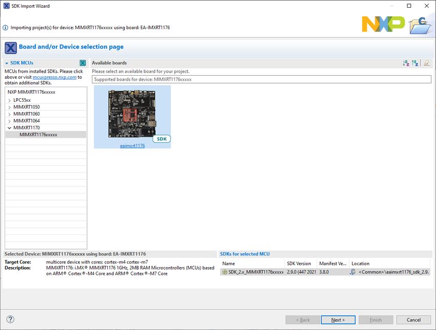
iMX RT Developer’s Kit - Program Development Guide                                           Page 3

                                              Table of Contents
                                               1 Document Revision History                                    5

                                               2 Get Started with Program Development                         6
                                               2.1     Downloading the SDK                                     6
                                               2.2     About the SDK                                           6
                                               2.3     Preparing the Hardware                                  7
                                               2.4     Getting Started With a Specific IDE                     7

                                               3 Getting Started with Keil uVision/MDK                        8
                                               3.1     Install the SDK                                         8
                                               3.2     Install CMSIS Device Pack                               8
                                               3.3     Build an Example Application                            8
                                               3.4     Run an Example Application                              9

                                               4 Getting Started with IAR Embedded Workbench                  12
                                               4.1     Install the SDK                                        12
                                               4.2     Build an Example Application                           12
                                               4.3     Run an Example Application                             13

                                               5 Getting Started with NXP MCUXpresso IDE                      15
                                               5.1     Install the SDK                                        15
                                               5.2     Build an Example Application                           15
                                               5.3     Run an Example Application                             18
                                               5.4     Target Memory                                          19
                                               5.5     Troubleshooting                                        22

                                               6 Debug Interface                                              23
                                               6.1     J-LINK/J-TRACE Support                                 23
                                               6.1.1    Install J-LINK Software                               23
                                               6.1.2    MCUXpresso                                            23
                                               6.1.3    Keil uVision                                          24
                                               6.2     Debug Troubleshooting                                  25

                                               7 Standalone Program Download                                  27
                                               7.1     Install the Required Software                          27
                                               7.2     Prepare the Program to Flash                           27
                                               7.3     Booting an Unsigned Image                              28
                                               7.4     Booting an Authenticated or Encrypted Image            30

                                               8 Terminal Application Setup                                   31
                                               8.1     UART-to-USB Bridge                                     31
                                               8.2     Terminal Application on the PC                         31
                                               8.2.1    Tera Term Terminal Emulation Application              32

Copyright 2021 © Embedded Artists AB
iMX RT Developer’s Kit - Program Development Guide                                    Page 4

                                               8.2.2   PuTTY terminal emulation application            33

                                               9 Booting from External Memory                          34

                                               10 Things to Note                                       37
                                               10.1    ESD Precaution                                  37
                                               10.2    General Handling Care                           37
                                               10.3    OTP Fuse Programming                            37

                                               11 Disclaimers                                          38
                                               11.1    Definition of Document Status                   39

Copyright 2021 © Embedded Artists AB
iMX RT Developer’s Kit - Program Development Guide          Page 5

                        1 Document Revision History
                        Revision       Date         Description
                        PA1            2020-03-03   First release

Copyright 2021 © Embedded Artists AB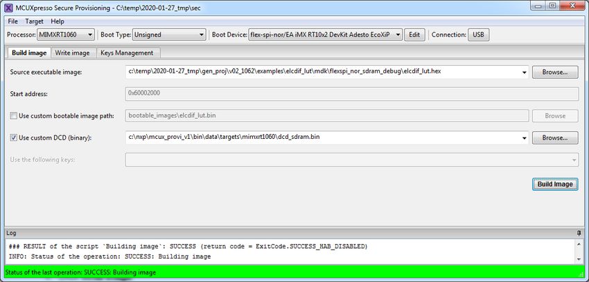
iMX RT Developer’s Kit - Program Development Guide Page 6
2 Get Started with Program Development
This chapter contains information about how to get started with program development on the iMX RT1176
uCOM Developer’s Kit.
To start program development you need the following things, all of them:
1. Patched version of MCUXpresso SDK - this is a package of sample software from NXP that has
been patched by Embedded Artists to work with the iMX RT Developer’s Kit. The zip-file can be
downloaded from http://imx.embeddedartists.com.
2. Integrated Development Environment (IDE)
a. NXP MCUXpresso, Keil uVision/MDK and IAR Embedded Workbench. Update to
latest version of respective IDE.
b. Programming of the flash is also supported via NXP's MCUXpresso Secure Provisioning
Tools standalone application but it is not a suitable tool to use during program
development.
3. JTAG probe to be able to download the application to SRAM, SDRAM or the flash memory and in
general to be able to debug - set breakpoints, inspect memory, etc.
a. The low-cost MCU-Link or LPC-Link2 are excellent choices. Keil ULINK2 and ULINKplus,
as well as Segger JLINK, are also excellent debug probes.
b. Technically it is possible to program/flash without a JTAG probe (via NXP's MCUXpresso
Secure Provisioning Tools application), but it is strongly recommended to use the proper
tool for debugging - i.e., use a JTAG probe!
4. And of course the iMX RT Developer's Kit!
2.1 Downloading the SDK
Starting with SDK version 2.9.0 and going forward, Embedded Artists has published a version of the SDK
that has already been patched to work with the iMX RT1176 uCOM Developer’s Kit. The file can be
downloaded from http://imx.embeddedartists.com and will have a filename like
eaimxrt1176_sdk__.zip
2.2 About the SDK
NXP’s SDK builder (https://mcuxpresso.nxp.com/en/) was used to generate an SDK.
Depending on which options are selected it limits the number of examples that can be downloaded. The
SDK with the broadest set of examples is the Windows/All IDEs/All Examples/FreeRTOS combination and
that is the combination that was selected for the patched SDK.
In general this is what has been patched (see the release notes for more detail):
The memory configuration (e.g. size of SDRAM) is changed to match the Developer’s Kit
The flash configuration (e.g. size/model/make) is changed to match the Developer’s Kit. This
includes changes to selected flash algorithms and flash headers
Use of I2C busses, UARTs and pinning is changed where needed
Buttons and LEDs are remapped to work on the Developer’s Kit
Copyright 2021 © Embedded Artists AB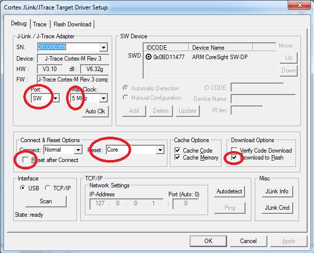
iMX RT Developer’s Kit - Program Development Guide Page 7
Drivers for peripherals unique to the Developer’s Kit are added. This includes for example
o GPIO Expander PCA6416
o PWM Expander PCA9530
o EEPROM for MAC address
LWIP projects are modified to read the MAC address from the onboard I2C EEPROM
This has been added:
Wi-Fi/Bluetooth examples are added for 1LV/43012 and 1MW/43455 in the cases where the SDK
only support 1DX/4343W.
This has been removed:
All projects for the expansion board AGM01
2.3 Preparing the Hardware
Please follow the instructions on the getting started page for the uCOM Developer's Kit in order to power the
board and connect to the console (UART-to-USB bridge).
https://www.embeddedartists.com/getting-started-with-ucom-developers-kit/
2.4 Getting Started With a Specific IDE
The following chapters will describe how to get started with a number of different IDEs.
Chapter 3 describes Keil uVision/MDK.
Chapter 4 describes IAR Embedded Workbench.
Chapter 5 describes NXP MCUXpresso.
Copyright 2021 © Embedded Artists AB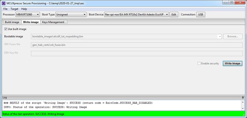
iMX RT Developer’s Kit - Program Development Guide                                                                  Page 8

                        3 Getting Started with Keil uVision/MDK
                        This section is a guide to open, build and debug an example application using Keil uVision/MDK with the
                        SDK that was downloaded in 2.1 . It is assumed that you have this development environment installed on
                        your computer.

                        3.1         Install the SDK
                        Unpack the SDK zip file that was downloaded in 2.1 somewhere on the local file system. It is suggested to
                        use a very short path as the SDK has a deep folder structure and a too long path can cause problem in
                        Windows.
                        The folder that the SDK is unpacked into will be referred to as  in the following
                        sections.

                        3.2         Install CMSIS Device Pack
                        After the MDK tools are installed, Cortex Microcontroller Software Interface Standard (CMSIS) device packs
                        must be installed to fully support the device from a debug perspective. These packs include things such as
                        memory map information, register definitions and flash programming algorithms. Follow these steps to install
                        the IMXRT105x CMSIS pack or IMXRT106x CMSIS pack.
                               1. Start Keil uVision
                               2. Start the Pack Installer tool with this button on the toolbar:
                               3. Browse to MIMXRT1176 in the device tree (NXP→MIMXRT1176→MIMXRT1176xxxxx) and then
                                  click the Install button next to the package with a "_DFP" in the name. Note that the button in the
                                  image below has "Update" as the package has already been installed.

                               4. Note that this operation can take a very long time to complete (~20 minutes) so don’t abort if it
                                  looks like the installer has frozen.

                        3.3         Build an Example Application
                        The following steps will guide you through opening the hello_world application for Cortex-M7. These steps
                        may change slightly for other example applications as some of these applications may have additional
                        layers of folders in their path.
                               1.      If not already done, open the desired example application workspace in:
                                       /boards/evkmimxrt1170//
                                       //mdk
                                       The workspace file is named .uvmpw, so for this specific example, the actual
                                       path is:

Copyright 2021 © Embedded Artists AB
iMX RT Developer’s Kit - Program Development Guide                                                                     Page 9

                                       /boards/evkmimxrt1170/demo_apps/
                                       hello_world/cm7/mdk/hello_world_demo_cm7.uvmpw

                               2. Select the desired build target from the drop-down.
                                  For this example, select the “flexspi_nor_debug” target.

                                       The target name indicates from where the application is executing, see table below. Release
                                       targets have a higher compiler optimization degree making the target less suitable for debugging.
                                       Available targets differ from example to example but here are some of the more common ones.

                                         sdram_debug               The application runs in internal SRAM but with data in
                                         sdram_release             external SDRAM
                                         sdram_txt_debug           The application runs in external SDRAM but with data in
                                         sdram_txt_release         internal SRAM
                                         debug                     The application runs in internal SRAM
                                         release
                                         flexspi_nor_debug         The application runs in external flash, which must be
                                         flexspi_nor_release       programmed/flashed before use.

                                       Note that each of the targets have its own set of options so changing for example include path in
                                       one target does not affect the other targets.
                               3. To build the demo project, select the "Rebuild" button, highlighted in red.

                               4. The build will complete without errors.

                        3.4        Run an Example Application
                        To download and run the application, perform these steps:
                               1. Prepare the hardware as described in chapter 2.3 and power it on.
                               2. Open the terminal application on the PC, such as TeraTerm or PuTTY, and connect to the virtual
                                  COM port. Configure the terminal with 115200 baud, 8N1.

Copyright 2021 © Embedded Artists AB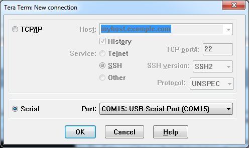
iMX RT Developer’s Kit - Program Development Guide                                                            Page 10

                                       You can alter the baud rate by searching for the BOARD_DEBUG_UART_BAUDRATE define in
                                       file: board.h
                               3. Select the Debug menu and then Start/Stop Debug Session, or simply press Ctrl+F5.
                                  The application will then be downloaded into SRAM.

                               4. Run the code by clicking the “Run” button (or tress F5) to start the application.

Copyright 2021 © Embedded Artists AB
iMX RT Developer’s Kit - Program Development Guide Page 11
5. The hello_world application is now running and a banner is displayed on the terminal. If this is not
true, check your terminal settings and connections.
Copyright 2021 © Embedded Artists ABiMX RT Developer’s Kit - Program Development Guide Page 12
4 Getting Started with IAR Embedded Workbench
This section is a guide to open, build and debug an example application using IAR Embedded Workbench. It
is assumed that you have this development environment installed on your computer.
4.1 Install the SDK
Unpack the SDK zip file that was downloaded in 2.1 somewhere on the local file system. It is suggested to
use a very short path as the SDK has a deep folder structure and a too long path can cause problem in
Windows.
The folder that the SDK is unpacked into will be referred to as in the following
sections.
4.2 Build an Example Application
The following steps will guide you through opening the hello_world application for Cortex-M7. These steps
may change slightly for other example applications as some of these applications may have additional
layers of folders in their path.
1. If not already done, open the desired example application workspace in:
/boards/evkmimxrt1170//
//iar
The workspace file is named .eww, so for this specific example, the actual path
is:
/boards/ evkmimxrt1170/demo_apps/
hello_world/cm7/iar/ hello_world_demo_cm7.eww
2. Select the desired build target from the drop-down.
For this example, select the “flexspi_nor_debug” target.
Copyright 2021 © Embedded Artists ABiMX RT Developer’s Kit - Program Development Guide Page 13
The target name indicates from where the application is executing, see table below. The name also
indicates if it is a release or debug target. Release targets have a higher compiler optimization
degree making the target less suitable for debugging. Available targets differ from example to
example but here are some of the more common ones.
sdram_debug The application runs in internal SRAM but with data in external
sdram_release SDRAM
sdram_txt_debug The application runs in external SDRAM but with data in internal
sdram_txt_release SRAM
debug The application runs in internal SRAM
release
flexspi_nor_debug The application runs in external flash, which must be
flexspi_nor_release programmed/flashed before use.
3. Note that the target has its own set of options so changing for example include path in one target
does not affect the other targets.
4. To build the demo application, click the “Make” button, highlighted in red below.
5. The build completes without errors.
4.3 Run an Example Application
To download and run the application, perform these steps:
1. Prepare the hardware as described in chapter 2.3 and power it on.
2. Open the terminal application on the PC, such as TeraTerm or PuTTY, and connect to the virtual
COM port. Configure the terminal with 115200 baud, 8N1.
You can alter the baud rate by searching for the BOARD_DEBUG_UART_BAUDRATE define in
file: board.h
3. Click the "Download and Debug" button to download the application to the target.
Copyright 2021 © Embedded Artists ABiMX RT Developer’s Kit - Program Development Guide Page 14
4. The application is then downloaded to the target and automatically runs to the main() function.
5. Run the code by clicking the "Go" button to start the application.
6. The hello_world application is now running and a banner is displayed on the terminal. If this is not
true, check your terminal settings and connections.
Copyright 2021 © Embedded Artists ABiMX RT Developer’s Kit - Program Development Guide Page 15
5 Getting Started with NXP MCUXpresso IDE
This section is a guide to open, build and debug an example application using NXP MCUXpresso IDE. It is
assumed that you have this development environment installed on your computer.
5.1 Install the SDK
MCUXpresso requires the SDK to be installed before it can be used. To do that start MCUXpresso and then
drag-n-drop the SDK zip file that was downloaded in 2.1 to the "Installed SDKs" tab in MCUXpresso:
During the installation MCUXpresso will make a copy of the zip file that you drag-n-dropped so it is ok to
delete it afterwards if you don't need it for one of the other IDEs.
5.2 Build an Example Application
The following steps will guide you through opening the hello_world application from the SDK.
1. Install the SDK as described in section 5.1 if you have not done so already
2. Click the "Import SDK example(s)…" link in the Quickstart Panel
Copyright 2021 © Embedded Artists ABiMX RT Developer’s Kit - Program Development Guide Page 16
3. Select the MIMXRT1176xxxxx and eaimxrt1176. Click Next to go to the project selector.
Copyright 2021 © Embedded Artists ABiMX RT Developer’s Kit - Program Development Guide Page 17
4. Select the hello_world example for Cortex-M7 (ends in _cm7) and make sure to switch from
Semihost to UART for the SDK Debug Console.
5. Click finish to have MCUXpresso import and set up the selected project.
6. Click Build in the Quickstart Panel
7. The program builds without errors
Copyright 2021 © Embedded Artists ABiMX RT Developer’s Kit - Program Development Guide Page 18
5.3 Run an Example Application
To download and run the application, perform these steps:
1. Prepare the hardware as described in chapter 2.3 and power it on.
2. Open the terminal application on the PC, such as TeraTerm or PuTTY, and connect to the virtual
COM port. Configure the terminal with 115200 baud, 8N1.
You can alter the baud rate by searching for the BOARD_DEBUG_UART_BAUDRATE define in
file: board.h
3. Click the "Debug" button in the Quickstart Panel to download the application to the target.
4. The application is then downloaded to the target and automatically runs to the main() function.
5. Run the code by clicking the "Resume" button to start the application.
6. The hello_world application is now running and a banner is displayed on the terminal. If this is not
true, check your terminal settings and connections.
Copyright 2021 © Embedded Artists ABiMX RT Developer’s Kit - Program Development Guide Page 19
5.4 Target Memory
Almost all of the examples for MCUXpresso are setup to run from flash. If the flash is used, or not, can be
seen when compiling:
Copyright 2021 © Embedded Artists ABiMX RT Developer’s Kit - Program Development Guide Page 20
To run the program in RAM/SDRAM (if it is small enough to fit):
1. Open the Project -> Properties menu and navigate to MCU Settings
2. Select the BOARD_FLASH row in the table and then click the Delete button to remove the flash.
Copyright 2021 © Embedded Artists ABiMX RT Developer’s Kit - Program Development Guide Page 21
3. Go to Settings and the Preprocessor entry
4. There are three symbols that must be changed. The symbols are
XIP_BOOT_HEADER_DCD_ENABLE, XIP_EXTERNAL_FLASH and
XIP_BOOT_HEADER_ENABLE. Double-click each one and change the value from 1 to 0 to
disable the feature.
5. Build the project and look at the output. The BOARD_FLASH is no longer present and instead the
SDRAM is used:
Copyright 2021 © Embedded Artists ABiMX RT Developer’s Kit - Program Development Guide Page 22
5.5 Troubleshooting
It is possible that a dialog like this pops up when building your project:
That error message appears because the project was not 100% imported and this happens sometimes if
you select multiple projects to import at the same time. To fix the problem you have two choices:
Option 1: Right click the project, select Delete and make sure that the checkbox for deleting the content on
the disk is filled in. You can then import that project again.
Option 2: Switch to a new workspace and only import that project.
Copyright 2021 © Embedded Artists ABiMX RT Developer’s Kit - Program Development Guide Page 23
6 Debug Interface
It is strongly recommended to use a debug/JTAG probe during program development. The low-cost MCU-
Link or LPC-Link2 are excellent choices. Keil ULINK2 and ULINKplus, as well as Segger JLINK, are also
excellent debug probes.
There is a Cortex Debug interface connectors (J11) on the uCOM Carrier board. It is a 2x5 pos, 50 mil pitch
connector with a shroud. Note that pin 7 is present. Some debug probe connectors have plugged pin 7.
Such a cable connector cannot be used.
Debug Connectors
J11
Figure 1 – Debug Interfaces on uCOM Carrier board
Note that due to the powering sequencing requirements on the i.MX family, the debug probe I/O
voltage MUST follow the i.MX I/O voltage.
The debug adapter must not drive any output higher than the Vcc/Vref voltage (and if that voltage
is zero, then the debug adapter must not drive any output signal). Vcc/Vref is pin 1 on J11.
Make sure the debug probe does not have a fixed output voltage, but rather follow Vcc/Vref. If
using LPC-Link2 as debug interface, make sure there is NO jumper inserted in JP2 on the LPC-
Link2.
6.1 J-LINK/J-TRACE Support
This section describes the steps necessary to get the Segger J-TRACE to work with NXP MCUXpresso and
Keil uVision. The same instructions are likely to work for Segger J-LINK as well, but it has not been verified.
6.1.1 Install J-LINK Software
Use version v6.90a or later to get the best support for J-TRACE/J-LINK. The latest version can be found
here: https://www.segger.com/downloads/jlink/.
6.1.2 MCUXpresso
Build and then launch the debugger. MCUXpresso will detect the J-LINK / J-TRACE and configure itself
correctly.
Copyright 2021 © Embedded Artists ABiMX RT Developer’s Kit - Program Development Guide Page 24
6.1.3 Keil uVision
All projects have been configured to use CMSIS-DAP as debug hardware. Follow the steps below to switch
to J-LINK/J-TRACE.
Change the Debugger from the default CMSIS-DAP to J-LINK / J-TRACE Cortex, as shown in picture below:
Figure 2 – Setting Debug Interface in Keil uVision
Open the settings dialog and change to the following settings:
Figure 3 – Configuring J-TRACE/J-LINK Interface in Keil uVision
Copyright 2021 © Embedded Artists ABiMX RT Developer’s Kit - Program Development Guide Page 25
Switch to the Flash Download tab and make sure that the flash algorithm is correct. It should be
MIMXRT117x 16mB QuadSPI Nor Flash.
Figure 4 – Configuring Flash Programming for J-TRACE/J-LINK Interface in Keil uVision for iMX RT1176
6.2 Debug Troubleshooting
In some cases the IDE complains about not being able to connect to the target. This is most likely because
the program already running on the target is interfering. The solution is to put the hardware in ISP mode
before starting the flash/debug operation in the IDE. To do this:
1. Push and hold down the ISP enable button
2. Press the Reset button
3. Release the Reset button
4. Wait 1 second
5. Release the ISP enable button
If the LPC-Link2 debugger is used then there are some additional things to note:
1. Make sure that the J2 jumper on the LPC-Link2 is not inserted. If the jumper is inserted/closed then
the target will be powered by the LPC-Link2 which might be too much power for the usb port that
the LPC-Link2 is connected to.
2. If the LPC-Link2 is not found by the IDE and you are working on a laptop then try using a powered
usb hub instead.
3. The troubleshooting section in this forum post has a couple of additional things to try:
https://community.nxp.com/thread/388964
4. There is a Using and troubleshooting LPC-Link2 in the Appendix - Additional Hints and Tips of the
User Guide for MCUXpresso IDE. The location of the document is
c:\nxp\MCUXpressoIDE_11.0.0_2516\MCUXpresso_IDE_User_Guide.pdf if the IDE was installed
with the default settings (correct path for your specific version of MCUXpresso).
Copyright 2021 © Embedded Artists ABiMX RT Developer’s Kit - Program Development Guide Page 26 Copyright 2021 © Embedded Artists AB
iMX RT Developer’s Kit - Program Development Guide Page 27
7 Standalone Program Download
This chapter describes how to download an application to the iMX RT board without using the IDE. Note that
this section does not describe how to create the application code (create the application, compile and link it).
It is assumed that a binary file exist that represent the application program.
As a reminder, there are two basic methods for program download:
ISP over USB Program Download
ISP is short for In-System Programming. The i.MX RT MCU contains a bootloader in ROM that can
be enabled by pressing the ISP Enable push-button.
An application (MCUXpresso Secure Provisioning Tools) provided by NXP is needed on the PC for
downloading and flashing the application code. It is this method that will be described in this
chapter.
o This method of programming is useful during production
o The MCUXpresso Secure Provisioning Tools application is needed to generate an
authenticated or encrypted image of the application.
o Technically it is possible to program/flash without a JTAG probe (via NXP's MCUXpresso
Secure Provisioning Tools application), but it is strongly recommended to use the proper
tool for debugging - i.e., use a JTAG probe!
SWD/JTAG Debug Interface
Using this method, the application can be downloaded to internal SRAM, to external SDRAM or
external EcoXiP flash.
This method is tightly integrated with the Integrated Development Environment (IDE) used. Specific
scripts (and sometimes flash programming algorithms) must exist for the used IDE. Currently such
scripts and drivers exist for Keil uVision/MDK, NXP MCUXpresso and IAR Embedded Workbench.
For other IDEs, check supported functions.
o There are many different SWD/JTAG interfaces on the market. NXP has created the low-
cost MCU-Link and LPC-LINK2, Keil has ULINK2/ULINKpro, Segger has J-LINK, etc.
Note that as of 2021-03-03 the Secure Provisioning Tool had not yet added support for iMX
RT1176 but it is expected by end of April 2021. The screenshots in this chapter are from iMX
RT1060 and will be updated as the new version is released.
7.1 Install the Required Software
Download MCUXpresso Secure Provisioning Tools from NXP's website. It can be found under the Tools &
Software tab for each MCU or directly here. The tool is available for Windows, MacOS and Linux but this
document only covers the Windows use case. Patching and using the MacOS and Linux versions should be
very similar with only paths and file names varying.
The default installation location is c:\nxp\MCUX_Provi_v2.1\ which will be referred to as
from now on.
7.2 Prepare the Program to Flash
A program can be setup to run directly in external nor flash, in internal SRAM or in (external) SDRAM and
the project must be modified accordingly. This is described in detail in section 6.1.3 of the User Manual -
MCUXpresso Secure Provisioning Tools that comes with the installation of the tool (filename: MCUXpresso
Copyright 2021 © Embedded Artists ABiMX RT Developer’s Kit - Program Development Guide Page 28
Secure Provisioning Tools.pdf) or it can be viewed here: https://www.nxp.com/docs/en/user-
guide/MCUXSPTUG.pdf
As an example, this is what was needed to prepare the led_blinky demo application:
1) Open the project
\eaimxrt1176_sdk_2.9.0\boards\evkmimxrt1170\dem
o_apps\led_blinky\cm7\mdk\iled_blinky_cm7.uvprojx
2) Select the “sdram_debug” target
3) Open Project->Options-Output and make sure that “Create HEX File” is selected
4) Switch to the Linker tab and click Edit to open the scatter file in the background
5) Close the dialog with the OK button (to save the change made in step 3)
6) Modify the following lines in the scatter file:
#define m_interrupts_start 0x00000000
#define m_interrupts_size 0x00000400
#define m_text_start 0x00000400
#define m_text_size 0x0003FC00
#define m_data_start 0x80000000
#define m_data_size 0x01000000
to look like this:
#define m_interrupts_start 0x80002000
#define m_interrupts_size 0x00000400
#define m_text_start 0x80002400
#define m_text_size 0x0001DC00
#define m_data_start 0x80020000
#define m_data_size 0x00DE0000
7) Save the file
8) Press F7 or Project->Build Target
9) There should now be a hex file here:
\eaimxrt1176_sdk_2.9.0\boards\evkmimxrt1170\dem
o_apps\led_blinky\cm7\mdk\sdram_debug\iled_blinky_cm7.hex
7.3 Booting an Unsigned Image
Unsigned image is typically used for development. It's recommended to start with this boot type before
working with secured images to verify that the executable image works properly.
The first step is to convert the prepared application into a bootable image:
Copyright 2021 © Embedded Artists ABiMX RT Developer’s Kit - Program Development Guide Page 29
1. Start with a new workspace, File->New Workspace…
2. Select a location for the workspace and which processor to use. Click Create.
3. Make sure that Boot Type is Unsigned
4. Set Boot Device to flex-spi-nor/IS25LPxxxA_IS25WPxxxA
5. Switch to the Build Image tab
6. Select the Source executable image that was prepared in the previous section, i.e.
iled_blinky_cm7.hex
7. If (and only if) the application uses SDRAM, select the Use custom DCD option and point to the
dcd_sdram.bin file from the \bin\data\targets\mimxrt*\ folder
8. Click Build Image
To write the image:
1. Switch to the Write Image tab
2. Make sure that the Use built image option is selected
3. Connect the hardware to the PC using micro USB cables in both J26 and J29 connectors
4. Put the hardware in ISP mode:
a. Push and hold down the ISP enable button
b. Press the Reset button
c. Release the Reset button
d. Wait 1 seconds
Copyright 2021 © Embedded Artists ABiMX RT Developer’s Kit - Program Development Guide Page 30
e. Release the ISP enable button
5. Press the Write Image button
6. When finished, press the Reset button on the hardware to run the program
7.4 Booting an Authenticated or Encrypted Image
The MCUXpresso Secure Provisioning Tools support authenticated (signed) and encrypted
(signed+encrypted) images. This is described in detail in the User Manual for the tool, in sections 5.8, 6.1.5
and 6.1.6. A couple of very important notes:
1. Encrypted images cannot be used for applications that execute directly in the flash (XiP).
2. Burning the fuses in the processor is an irreversible operation. If the fuses are burned and the key
is lost then there is no way to burn anything again on that hardware so make sure to backup the
(generated) keys BEFORE burning them to the hardware.
3. If the instructions mentions setting the SW7 DIP to the board to 0001 it means putting the board
into ISP mode. This is done on the Developers Kit by:
a. Push and hold down the ISP enable button
b. Press the Reset button
c. Release the Reset button
d. Wait 1 seconds
e. Release the ISP enable button
Copyright 2021 © Embedded Artists ABiMX RT Developer’s Kit - Program Development Guide Page 31
8 Terminal Application Setup
This chapter contains information about the terminal connection that exist on the uCOM Carrier Board, and
how to setup a terminal application on the PC. The terminal connection connects UART1 of the i.MX RT to a
virtual COM port over the USB interface available on J29. The terminal is commonly used during program
development.
8.1 UART-to-USB Bridge
The UART-to-USB bridge chip (FT230XS-R from FTDI) on the uCOM Carrier Board connects to UART
channel #1 on the i.MX RT. It exists to simplify connection to a PC because serial ports are not so common
any more, especially not on laptops. The USB port also offers the possibility to power the board.
There are two LEDs, transmit from the board (LED9) and receive to the board (LED8), that signal
communication activity.
See picture below for locating relevant components.
USB micro-B Connector UART channel jumper
J29 JP19 Receive Transmit
Insert to connect UART receive LED LED
pin of uCOM processor
Figure 5 – UART-to-USB Bridge
8.2 Terminal Application on the PC
Begin by connecting the micro-B USB connector to J29, see picture above. Connect the other end of the
USB cable to the PC. The PC will typically immediately begin installing drivers automatically for the UART-
to-USB bridge that creates a Virtual COM port, if they are not already installed. If you have problems the
drivers can be downloaded from the links below:
http://www.ftdichip.com/Drivers/VCP.htm
http://www.ftdichip.com/Support/Documents/InstallGuides.htm
When the driver has been installed, a new COM port will listed under “Ports” in the Device Manager as
shown in Figure 6. Please note that the actual port number will most likely be different on your computer.
Copyright 2021 © Embedded Artists ABiMX RT Developer’s Kit - Program Development Guide Page 32
Figure 6 – Virtual COM port shown in device manager
The next step is to open a terminal application and attached it to the Virtual COM port that has just been
created. The baud rate should be 115200.
Some development environments/IDEs have a built-in terminal application that can be used. Sometimes it is
better to have a terminal application with more features. For increased flexibility, we recommend using any
of the two alternative terminal applications presented in the following sub-sections.
8.2.1 Tera Term Terminal Emulation Application
We recommend that you use Tera Term which can be downloaded and installed from either of the links
below.
https://ttssh2.osdn.jp/index.html.en
http://sourceforge.jp/projects/ttssh2/releases/
Launch Tera Term. The first time it launches, it will show you the following dialog. Select the serial option.
Assuming the USB cable is connected to the iMX OEM Carrier Board, there should be a COM port
automatically populated in the list.
Figure 7 – Tera Term New Connection Window
Configure the serial port settings (using the COM port number identified earlier) to 115200 baud rate, 8 data
bits, no parity and 1 stop bit. To do this, go to Setup Serial Port and change the settings.
Copyright 2021 © Embedded Artists ABiMX RT Developer’s Kit - Program Development Guide Page 33
Figure 8 – Tera Term Serial Port Setup
Verify that the connection is open. If connected, Tera Term will show something like below in its title bar.
Figure 9 – Tera Term Menu
8.2.2 PuTTY terminal emulation application
Alternatively you can use PuTTY. It is another commonly used terminal emulation application. PuTTY can
be downloaded and installed from the link below.
http://www.chiark.greenend.org.uk/~sgtatham/putty/download.html
Launch PuTTY by either double clicking on the *.exe file you downloaded or from the Start menu, depending
on the type of download you selected.
In the window that launches, select the Serial radio button and enter the COM port number that you
determined earlier. Also enter the baud rate, in this case 115200.
Figure 10 – PuTTY New Session Configuration
Click Open to open the serial connection. Assuming the FTDI cable is connected and you entered the
correct COM port, the terminal window will open. If the configuration is not correct, PuTTY will alert you.
Copyright 2021 © Embedded Artists ABiMX RT Developer’s Kit - Program Development Guide Page 34
9 Booting from External Memory
The i.MX RT does not have any internal flash memory for storing the application. It has to be stored in an
external memory. On the iMX RT OEM board, this external memory is an OctalSPI. The i.MX RT MCU
always boots (i.e., starts executing) from this memory.
First, let's investigate the three use-cases when executing an application. The picture below illustrates the
first main use-case when executing an application.
i.MX RT Memory from where
application is
Cortex-M7 Internal 1b - Execute from SRAM executed
core SRAM
1a - Copy application into SRAM during boot time
16 MByte 32 MByte
QSPI Flash SDRAM
Figure 11 – i.MX RT and QSPI flash - Executing from SRAM
1. The application is stored in the QSPI flash and the bootloader (inside the i.MX RT) copies it into
internal SRAM and then run from there.
a. The execution performance will be the highest in this setup.
b. During program development the application is just downloaded to internal SRAM by the
debugger. There is no need to first download the application to the QSPI flash memory.
The address (in SRAM) where the application is downloaded is the same that it will be
copied to by the on-chip bootloader in a final deployed system.
Copyright 2021 © Embedded Artists ABiMX RT Developer’s Kit - Program Development Guide Page 35
The second use-case is illustrated below. It is the default option supported when compiling and building the
Xip targets.
i.MX RT Memory from where
application is
Cortex-M7 Internal executed
core SRAM
16 MByte 32 MByte
QSPI flash SDRAM
Figure 12 – i.MX RT and QSPI flash - Executing from EcoXiP
2. The application is stored in the QSPI flash and also executed from there. In this case, the internal
SRAM is probably too small for the application or is simply used for other things like data storage.
a. The execution performance will be considerably lower than the performance when
executing from internal SRAM.
b. During program development the application must be downloaded/flashed to the QSPI
flash memory before debugging actually starts. This is normally handled automatically by
the IDE (Integrated Development Environment).
Copyright 2021 © Embedded Artists ABiMX RT Developer’s Kit - Program Development Guide Page 36
The third use-case is just a mixture of the two main ones. Two, or more memories, are used for storing
executable code.
i.MX RT Memory from where
application is
Cortex-M7 Internal executed
core SRAM
3b - Executing directly from all memories
3a - Copy application into SRAM and/or SDRAM
16 MByte 32 MByte
QSPI flash SDRAM
Figure 13 – i.MX RT and QSPI flash - Executing from all memories
3. The third setup is a mixture of the two above. Part of the application is copied into SRAM and/or
SDRAM and part is executed directly from the QSPI flash. A reason for placing part of an
application in SRAM can be a need for highest performance for a data processing algorithm or a
time critical interrupt service routine.
a. Note that this is a more complicated system architecture. The application must implement
a dynamic loader that can copy code from the QSPi flash to SRAM, either on-demand or
in a pre-scheduled way. The linker script can be much more complicated because of this.
There is no general solution for this system solution. Every system must be individually
investigated in order to select and implement the best solution.
Copyright 2021 © Embedded Artists ABiMX RT Developer’s Kit - Program Development Guide Page 37
10 Things to Note
10.1 ESD Precaution
Please note that the iMX RT uCOM Board and uCOM Carrier Board come
without any case/box and all components are exposed for finger touches – and
therefore extra attention must be paid to ESD (electrostatic discharge)
precaution.
Make it a habit always to first touch the metal surface of one of the USB,
SD or Ethernet connectors for a few seconds with both hands before
touching any other parts of the boards. That way, you will have the same
potential as the board and therefore minimize the risk for ESD.
Never touch directly on the iMX RT uCOM Board and in general as little as possible on the uCOM Carrier
Board. The push-buttons on the uCOM Carrier Board have grounded shields to minimize the effect of ESD.
Note that Embedded Artists does not replace boards that have been damaged by ESD.
10.2 General Handling Care
Handle the iMX RT uCOM Board and uCOM Carrier Board with care. The boards are not mounted in a
protective case/box and are not designed for rough physical handling. Connectors can wear out after
excessive use. The uCOM Carrier Board is designed for prototyping use, and not for integration into an end-
product.
For boards with LCD, do not exercise excessive pressure on the LCD glass area. That will damage the
display. Also, do not apply pressure on the flex cables connecting the LCD/touch screen. These are
relatively sensitive and can be damaged if too much pressure is applied to them.
Note that Embedded Artists does not replace boards where the LCD has been improperly handled.
10.3 OTP Fuse Programming
The i.MX RT MCU has on-chip OTP fuses that can be programmed. Once programmed, there is no
possibility to reprogram them.
iMX RT uCOM Boards are delivered with OTP fuse programming to boot from external QSPI flash. The rest
of the fuses are completely up to the user to decide if OTP fuses shall be programmed and in that case,
which ones.
Note that Embedded Artists does not replace iMX RT OEM Boards because of wrong OTP
programming. It’s the user’s responsibility to be absolutely certain before OTP programming and
not to program the fuses by accident.
Copyright 2021 © Embedded Artists ABiMX RT1052/1062 OEM Developer’s Kit - User’s Guide Page 38
11 Disclaimers
Embedded Artists reserves the right to make changes to information published in this document,
including, without limitation, specifications and product descriptions, at any time and without notice.
This document supersedes and replaces all information supplied prior to the publication hereof.
Customer is responsible for the design and operation of their applications and products using
Embedded Artists’ products, and Embedded Artists accepts no liability for any assistance with
applications or customer product design. It is customer’s sole responsibility to determine whether the
Embedded Artists’ product is suitable and fit for the customer’s applications and products planned, as
well as for the planned application and use of customer’s third party customer(s). Customers should
provide appropriate design and operating safeguards to minimize the risks associated with their
applications and products. Customer is required to have expertise in electrical engineering and
computer engineering for the installation and use of Embedded Artists’ products.
Embedded Artists does not accept any liability related to any default, damage, costs or problem which
is based on any weakness or default in the customer’s applications or products, or the application or
use by customer’s third party customer(s). Customer is responsible for doing all necessary testing for
the customer’s applications and products using Embedded Artists’ products in order to avoid a default
of the applications and the products or of the application or use by customer’s third party customer(s).
Embedded Artists does not accept any liability in this respect.
Embedded Artists does not accept any liability for errata on individual components. Customer is
responsible to make sure all errata published by the manufacturer of each component are taken note
of. The manufacturer's advice should be followed.
Embedded Artists does not accept any liability and no warranty is given for any unexpected software
behavior due to deficient components.
Customer is required to take note of manufacturer's specification of used components, for example
MCU, SDRAM and FLASH. Such specifications, if applicable, contains additional information that must
be taken note of for the safe and reliable operation. These documents are stored on Embedded Artists'
product support page.
All Embedded Artists’ products are sold pursuant to Embedded Artists’ terms and conditions of sale:
http://www.embeddedartists.com/sites/default/files/docs/General_Terms_and_Conditions.pdf
No license, express or implied, by estoppel or otherwise, to any intellectual property rights is granted
under this document. If any part of this document refers to any third party products or services it shall
not be deemed a license grant by Embedded Artists for the use of such third party products or
services, or any intellectual property contained therein or considered as a warranty covering the use in
any manner whatsoever of such third party products or services or any intellectual property contained
therein.
UNLESS OTHERWISE SET FORTH IN EMBEDDED ARTISTS’ TERMS AND CONDITIONS OF SALE
EMBEDDED ARTISTS DISCLAIMS ANY EXPRESS OR IMPLIED WARRANTY WITH RESPECT TO
THE USE AND/OR SALE OF EMBEDDED ARTISTS PRODUCTS INCLUDING WITHOUT
LIMITATION IMPLIED WARRANTIES OF MERCHANTABILITY, FITNESS FOR A PARTICULAR
PURPOSE (AND THEIR EQUIVALENTS UNDER THE LAWS OF ANY JURISDICTION), OR
INFRINGEMENT OF ANY PATENT, COPYRIGHT OR OTHER INTELLECTUAL PROPERTY RIGHT.
UNLESS EXPRESSLY APPROVED IN WRITING BY THE CEO OF EMBEDDED ARTISTS,
PRODUCTS ARE NOT RECOMMENDED, AUTHORIZED OR WARRANTED FOR USE IN MILITARY,
AIR CRAFT, SPACE, NUCLEAR, LIFE SAVING, OR LIFE SUSTAINING APPLICATIONS, NOR IN
PRODUCTS OR SYSTEMS WHERE FAILURE OR MALFUNCTION MAY RESULT IN PERSONAL
INJURY, DEATH, OR SEVERE PROPERTY OR ENVIRONMENTAL DAMAGE.
Resale of Embedded Artists’ products with provisions different from the statements and/or technical
features set forth in this document shall immediately void any warranty granted by Embedded Artists
Copyright 2021 © Embedded Artists ABiMX RT1052/1062 OEM Developer’s Kit - User’s Guide Page 39
for the Embedded Artists’ product or service described herein and shall not create or extend in any
manner whatsoever, any liability of Embedded Artists.
This document as well as the item(s) described herein may be subject to export control regulations.
Export might require a prior authorization from national authorities.
11.1 Definition of Document Status
Preliminary – The document is a draft version only. The content is still under internal review and
subject to formal approval, which may result in modifications or additions. Embedded Artists does not
give any representations or warranties as to the accuracy or completeness of information included
herein and shall have no liability for the consequences of use of such information. The document is in
this state until the product has passed Embedded Artists product qualification tests.
Approved – The information and data provided define the specification of the product as agreed
between Embedded Artists and its customer, unless Embedded Artists and customer have explicitly
agreed otherwise in writing.
Copyright 2021 © Embedded Artists ABYou can also read