HYBRID PARITY (SUPER) INVERTER - INSTALLER MANUAL - Solar myWorld
←
→
Page content transcription
If your browser does not render page correctly, please read the page content below
HYBRID PARITY
  (SUPER) INVERTER

      INSTALLER MANUAL
SUNSYNK-8K-SG01LP1 / SUNSYNK-8K-SG03LP1

   Global Tech China Ltd, 3 Floor, Wai Yip Industrial Building.
    171 Wai Yip Street, Kwun Tong, Kowloon, Hong Kong.
           Tel: +852 2884 4318 Fax: +8522884 4816
       www.sunsynk.com / sales@globaltech-china.com

                                                                  v.11 (03/30/22)
Australian Manual
     No country code is required since the unit is preset to the Australian standards

This inverter complies with IEC 62109-2 clause 13.9 for earth fault alarm monitoring. If an Earth
Fault Alarm occurs, the fault code F24 will be displayed on the inverter screen /the LED indica-
tor fault will light up.

SUNSYNK-8K-SG01LP1
SUNSYNK-8K-SG01LP3

Australia Main Dealer
HORTON SOLAR CONSULTING Pty. Ltd
166a King William Road
HYDE PARK SA 5061
+61(0)429 075 444
Website http://www.sunsynk.com
Contact leigh_horton@pm.me

Manufacturer
Sunsynk Limited ( Part of Global Tech )
171 Wai Yip Street
Kwun Tong
Kowloon
Tel: +852 2884 4318 Fax: +852 2884 4816
Website http://www.sunsynk.com
Contact Info@Globaltech-china.com

                                                          Hybrid Inverter | Installer Manual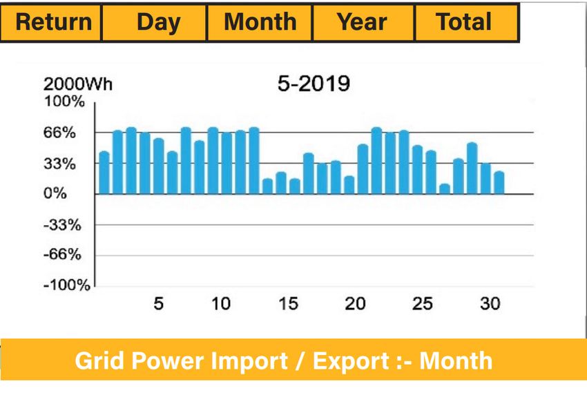
Table of Contents
1. SAFETY��������������������������������������������������������������������������������������������������������5
  1.1.   General Safety������������������������������������������������������������������������������������������������������������5
  1.2.   Symbols����������������������������������������������������������������������������������������������������������������������5
  1.3.   Safety Instructions�����������������������������������������������������������������������������������������������������6
  1.4.   Disposal Remarks������������������������������������������������������������������������������������������������������6

2. PRODUCT INTRODUCTION������������������������������������������������������������������������7
  2.1. Product Size���������������������������������������������������������������������������������������������������������������9
  2.2. Basic System Architecture���������������������������������������������������������������������������������������10

3. TECHNICAL SPECIFICATIONS�����������������������������������������������������������������11

4. INSTALLATION�������������������������������������������������������������������������������������������12
  4.1. Parts List�������������������������������������������������������������������������������������������������������������������12
  4.2. Selecting the Mounting Area�����������������������������������������������������������������������������������13
  4.3. System Diagram�������������������������������������������������������������������������������������������������������14
  4.4. Mounting the Inverter�����������������������������������������������������������������������������������������������14
  4.5. Function Port Definition�������������������������������������������������������������������������������������������16
  4.6. Battery Connection��������������������������������������������������������������������������������������������������17
    4.6.1. Recommended DC Battery Protection���������������������������������������������������������������18
  4.7. Connecting a Lithium Battery����������������������������������������������������������������������������������19
  4.8. Battery Temperature Sensor Connection����������������������������������������������������������������19
  4.9. Connecting the AC���������������������������������������������������������������������������������������������������21
    4.9.1. Recommended AC Surge Protector�������������������������������������������������������������������22
  4.10. Installing the CT Coil����������������������������������������������������������������������������������������������23
  4.11. Earth Connection (MANDATORY)��������������������������������������������������������������������������25
  4.12. Meter Connection���������������������������������������������������������������������������������������������������26
    4.12.1. System Connection for the CHNT Meter - EU��������������������������������������������������26
    4.12.2. System Connection for the Eastron Meter - EU�����������������������������������������������26
    4.12.3. System Connection for the CHNT Meter - US��������������������������������������������������27
    4.12.4. System Connection for the Eastron Meter - US�����������������������������������������������27
  4.13. Wiring System for Inverter�������������������������������������������������������������������������������������28
  4.14. PV Connection��������������������������������������������������������������������������������������������������������30
    4.14.1. PV Module Selection�����������������������������������������������������������������������������������������30
    4.14.2. PV Module Wiring���������������������������������������������������������������������������������������������30
    4.14.3. PV Protection����������������������������������������������������������������������������������������������������31
  4.15. Typical Application Diagram of Diesel Generator�������������������������������������������������31
  4.16. Single-Phase (230Vac) Parallel Connection Diagram�������������������������������������������32
  4.17. Split-Phase (120/240Vac) Parallel Connection Diagram���������������������������������������33
  4.18. Three-Phase (230/400Vac) Parallel Connection ���������������������������������������������������35
  4.19. Three-Phase (120/208Vac) Parallel Connection ���������������������������������������������������36
    4.19.1. Connected to the Grid��������������������������������������������������������������������������������������36
    4.19.2. Connected to a Generator��������������������������������������������������������������������������������37

                                                                                 Hybrid Inverter | Installer Manual
4.20. Three-Phase (120/208Vac) PCs Parallel Connection �������������������������������������������38

5. OPERATION�����������������������������������������������������������������������������������������������39
  5.1. Display����������������������������������������������������������������������������������������������������������������������39
  5.2. Switching ON/OFF����������������������������������������������������������������������������������������������������40
  5.3. Home Page���������������������������������������������������������������������������������������������������������������40
  5.4. Status Page��������������������������������������������������������������������������������������������������������������41
  5.5. System Flow Page����������������������������������������������������������������������������������������������������42
  5.6. Setup Page���������������������������������������������������������������������������������������������������������������43
  5.7. Set Time (Clock)�������������������������������������������������������������������������������������������������������43
  5.8. Set Company Name / Beeper / Auto dim����������������������������������������������������������������44
  5.9. Factory Reset and Lock Code ��������������������������������������������������������������������������������45
  5.10. Battery Setup Page������������������������������������������������������������������������������������������������46
  5.11. Generator & Battery Page��������������������������������������������������������������������������������������47
  5.12. Battery Discharge Page�����������������������������������������������������������������������������������������50
  5.13. Setting Up a Lithium Battery����������������������������������������������������������������������������������52
  5.14. Program Charge & Discharge Times���������������������������������������������������������������������57
  5.15. Grid Supply Page���������������������������������������������������������������������������������������������������60
  5.16. Connecting the DRM’s�������������������������������������������������������������������������������������������61
  5.17. Advanced Settings for Paralleling Inverters����������������������������������������������������������62
  5.18. Solar Power Generated������������������������������������������������������������������������������������������65
  5.19. Grid Power��������������������������������������������������������������������������������������������������������������65
  5.20. Advanced Settings for Wind Turbines�������������������������������������������������������������������66
  5.21. Advanced Settings for Auxiliary Load�������������������������������������������������������������������67
  5.22. Advanced Settings for Peak Shaving��������������������������������������������������������������������68
  5.23. Fault Codes������������������������������������������������������������������������������������������������������������69

6. COMMISSIONING��������������������������������������������������������������������������������������73
  6.1. Start-Up / Shutdown Procedure �����������������������������������������������������������������������������73
  6.2. Information for Commissioning the Inverter�����������������������������������������������������������74
  6.3. GDFI Fault�����������������������������������������������������������������������������������������������������������������75

7. MAINTENANCE������������������������������������������������������������������������������������������75

APPENDIX A���������������������������������������������������������������������������������������������������75

APPENDIX B���������������������������������������������������������������������������������������������������76

APPENDIX C���������������������������������������������������������������������������������������������������76

APPENDIX D���������������������������������������������������������������������������������������������������76

APPENDIX E���������������������������������������������������������������������������������������������������77

                                                                                Hybrid Inverter | Installer Manual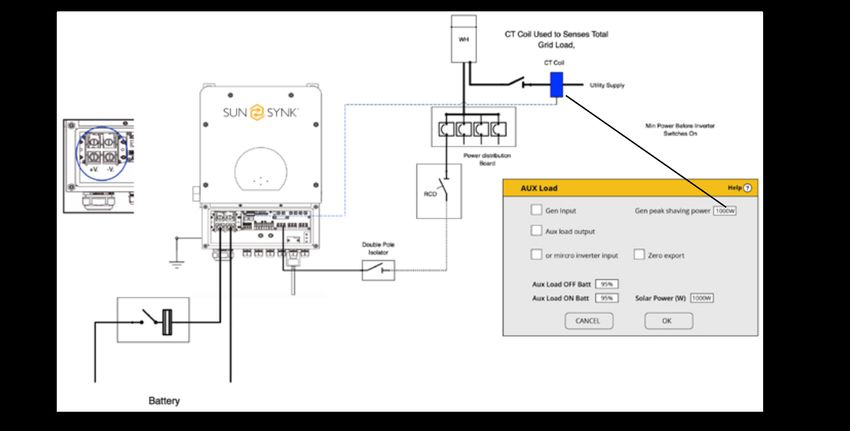
1. SAFETY
1.1. General Safety
This device should only be used in accordance o instructions within this manual and in
compliance with local, regional and national laws and regulations. Only allow this device
to be installed, operated, maintained, repaired by other persons who have also read and
understood this manual. Ensure the manual is included with this device should it be passed
to a third party.
DO NOT allow minors, untrained personnel, or person(s) suffering from a physical or mental
impairment that would affect their ability to follow this manual, install, maintain or repair this
device.
Any untrained personnel who might get near this device while it is in operation MUST be
informed that it is dangerous and instructed carefully on how to avoid injury.
1.2. Symbols
This symbol indicates information that if ignored, could result in per-
sonal injury or even death due to incorrect handling.
This symbol indicates information that if ignored, could result in per-
sonal injury or physical damage due to incorrect handling.
Indicates information that is considered important, but not haz-
ard-related.
Page | 5 Hybrid Inverter | Installer Manual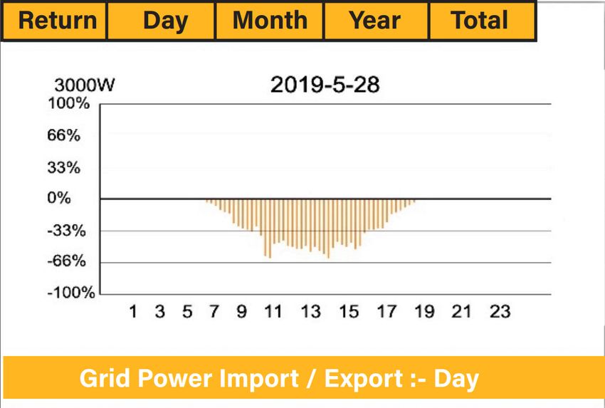
1.3. Safety Instructions
HIGH LIFE RISK DUE TO FIRE OR ELECTROCUTION.
The Sunsynk Single-Phase Hybrid Inverter can only be installed by a qualified li-
censed electrical contractor. This is not a DIY product.
Be sure to read this manual thoroughly before installation.
Do not attempt to install the inverter by yourself. Installation work must be carried out in
compliance with national wiring standards and by suitably qualified personnel only. Do not
turn on the power until all installation work is complete.
Do not disassemble the inverter. If you need repair or maintenance, contact a professional
service centre.
Always use an individual power supply line protected by a circuit breaker and operating on
all wires with a distance between contacts of at least 3mm for this unit.
The unit must be correctly grounded and the supply line must be equipped with a suitable
breaker and RCD to protect people.
Disconnect all wires/cables before performing any maintenance or cleaning to reduce the
risk of electrical shock.
The unit is not explosion-proof, so it should not be installed in an explosive atmosphere.
Never touch electrical components immediately after the power supply has been turned off
since the system can still have residual energy, so electric shock may occur. Therefore, after
turning off the power, always wait 5 minutes before touching electrical components.
This unit contains no user-serviceable parts. Always consult an authorised contractor for
repairs.
1.4. Disposal Remarks
DO NOT dispose this product with domestic waste!
Electrical devices should be disposed of in accordance with regional directives on electronic
and/ or electronic-waste disposal. In case of further questions, please consult your supplier. In
some cases, the supplier can take care of proper disposal.
Hybrid Inverter | Installer Manual Page | 6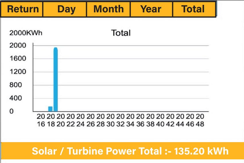
2. PRODUCT INTRODUCTION The Sunsynk Single-Phase Hybrid Inverter is a highly efficient power management tool that allows the user to hit those ‘parity’ targets by managing power-flow from multiple sources such as solar, mains power (grid) and generators, and then effectively storing and releasing power as and when utilities require. INTERACTIVE Easy and simple to understand display Supporting Wi-Fi or GSM monitoring Visual power flow screen Smart settable 3-stage MPPT charging for optimized battery performance Auxiliary load function Parallel / multi invert function grid-tied and off-grid COMPATIBLE Compatible with main electrical grid voltages or power generators Compatible with wind turbines 220V single phase, pure sinewave inverter Self-consumption and feed-in to the grid Auto restart while AC is recovering Auto earth bond feature (Via a relay) CONFIGURABLE Fully programmable controller Programmable supply priority for battery or grid Programmable multiple operation modes: on-grid/off-grid & UPS Configurable battery charging - current/voltage based on applications by LCD setting Configurable AC / solar / generator charger priority by LCD setting SECURE Overload/over-temperature/short-circuit protection Smart battery charger design for optimized battery protection Limiting function installed to prevent excess power overflow to grid APPLICATIONS Marine (vessel power management) Power shedding (home/office/factory) UPS (fuel-saving systems) Remote locations with solar and wind generators Building sites Military locations Telecommunication Page | 7 Hybrid Inverter | Installer Manual
1. Inverter Indicators          7. CAN Port                   13. Grid
2. LCD Display                  8. Battery input connectors   14. Generator input
3. Function Buttons             9. Function Port              15. Load
4. DC Switch                    10. Meter_CON port            16. WiFi Interface
5. Power on/off button          11. Parallel port
6. RS 485 port                  12. PV input with two MPPT

Hybrid Inverter | Installer Manual                                            Page | 8
2.1. Product Size

                    Inverter Size

Page | 9                            Hybrid Inverter | Installer Manual
2.2. Basic System Architecture
The following illustraton shows basic applicaton of this inverter.
It also includes following devices to have a Complete running system.
Generator or Utlity
PV modules
Consult with your system integrator for other possible system architectures depending on
your requirements.
This inverter can power all kinds of appliances in home or once environment, including mo-
tor type appliances such as refrigerator and air conditioner.
AC cable DC cable
WiFI
GPRS
Cloud services phone
Solar Backup Load On-Grid Home Load Grid
CT
Battery Smart Load Grid-connected Inverter Generator
ATS
Hybrid Inverter | Installer Manual Page | 103. TECHNICAL SPECIFICATIONS
Model SUNSYNK-8K-SG01LP1 / SUNSYNK-8K-SG03LP1
Product Type Hybrid Inverter
Enclosure IP65
Ambient Temperature -45ºC ~ 60ºC (>45ºC derating)
Protection Level Class I
Charge Mode
Battery Voltage 48Vd.c (40Vd.c ~ 60Vd.c)
Battery Current 190Ad.c (max.)
AC Input Voltage L/N/PE 220/230Va.c
AC Input Frequency 50/60Hz
AC Input Rated Current 36.4Aa.c
Max. AC Input Current 40Aa.c (max.)
Max. AC Input Power 8800W
Max. Apparent Output Power 8800VA
PV Input Voltage 370Vd.c (125Vd.c ~ 500Vd.c)
MPPT Input Voltage 150Vd.c ~ 425Vd.c
PV Input Current 22Ad.c + 22Ad.c
Max. PV Input Power 10400W
Max. PV Isc 28Ad.c + 28Ad.c
Utility-Interactive
AC Output Voltage L/N/PE 220/230Va.c
AC Output Frequency 50/60Hz
AC Output Rated Current 36.4Aa.c
Max. AC Output Current 40Aa.c (max.)
Max. AC Output Power 8800W
AC Output Rated Power 8800VA
AC Output Power Factor 0.8 leading to 0.8 lagging
Max. AC Isc 145Aa.c
Battery Discharge Voltage 40Vd.c ~ 60Vd.c
Battery Discharge Current 190Ad.c (max.)
Battery Discharge Power 8000W
Stand Alone
AC Output Voltage L/N/PE 220/230Va.c
AC Output Frequency 50/60Hz
AC Output Rated Current 36.4Aa.c
AC Output Rated Power 8800W
Max. Continuous AC Passthrough Current 50Aa.c
Peak Output Power 16000W (10 seconds)
Battery Discharge Voltage 40Vd.c ~ 60Vd.c
Max. Discharge Current 190A (max.)
VDE-AR-N 4105:1028-11; DINVDE V 0124-100:2020-06; IEC/
Compliance
EN62109-1/2:2010; IEC/EN62109-1/2:2011
Page | 11 Hybrid Inverter | Installer Manual4. INSTALLATION 4.1. Parts List Check the equipment before installation. Please make sure nothing is damaged in the package. You should have received the items in the following package: Hybrid Inverter | Installer Manual Page | 12
4.2. Selecting the Mounting Area DO NOT install the inverter in the following areas: Areas with high salt content, such as the marine environment. It will deteriorate the metal parts and possibly lead to water/dampness penetrating the unit. Areas filled with mineral oil or containing splashed oil or steam such as found in kitchens. It will deteriorate plastic parts of the unit, causing those parts to fail or allow water/damp to penetrate the unit. Areas that generate substances that adversely affect the equipment, such as sulphuric gas, chlorine gas, acid, or alkali. These can cause the copper pipes and brazed joints to corrode and fail to conduct electricity reliably. Areas that can cause combustible gas to leak, which contains suspended carbon-fibre or flammable dust, or volatile inflammable such as paint thinner or gasoline. Areas where there may be gas leaks and where gas may settle around the unit as this is a fire risk. Areas where animals may urinate on the unit or ammonia may be generated. High altitude areas (over 4000 metres above sea level). Environments where precipitation or humidity are above 95% Areas where the air circulation is too low. Page | 13 Hybrid Inverter | Installer Manual
4.3. System Diagram ALSO CONSIDER: Installing the indoor unit, outdoor unit, power supply cable, transmission cable, and remote control cable at least 1 metre away from any television or radio receiver. This will prevent TV reception interference or radio noise. This will prevent radio signal interference from external units that might interfere with the Wi-Fi or GSM monitoring. If children under 10 years old may approach the unit, take preventive measures so that they cannot reach and touch the unit. Install the indoor unit on the wall where the height from the floors is higher than 1600mm. For proper heat dissipation, allow a clearance of approximately 500mm to the side, 500mm above nd below the unit, and 1000mm to the front of the unit. 4.4. Mounting the Inverter Select installation locations that adequate to support the weight of the converter. Install this inverter at eye-level to allow the LCD to be read anytime. An appropriate ambient temperature is between -25 ~ 60°C to ensure optimal operation. Be sure to keep other objects and surfaces as shown in the figure to guarantee sufficient heat dissipation and have enough space to remove wires. For proper air circulation to dissipate heat, allow a clearance of approximately 50cm to the side. Hybrid Inverter | Installer Manual Page | 14
Risk of injury (Heavy Object)
 Remember that this inverter is heavy so users must be careful in handling the unit
 during installation especially when mounting or removing from a wall.

Choose the recommend drill head(as shown in below pic) to drill 4 holes on the wall, 52-60mm
deep.
1. Use a proper hammer to fit the expansion bolt into the holes.
2. Carry the inverter and holding it, make sure the hanger aim at the expansion bolt,fix the
   inverter on the wall.
3. Fasten the screw head of the expansion bolt to finish the mounting.

Page | 15                                              Hybrid Inverter | Installer Manual
4.5. Function Port Definition

Hybrid Inverter | Installer Manual   Page | 16
4.6. Battery Connection
For safe operation and compliance, a separate DC over-current protector or disconnect device
is required between the battery and the inverter. In some applications, switching devices may
not be required but over-current protectors are still required. Refer to the typical amperage in
the table below for the required fuse or circuit breaker size.

       Model                  Wire Size             Cable (mm2 )         Torque value (max.)
        8kW                    2AWG                     50                    5.2N.m

Please follow below steps to implement battery connection:
1. Please choose a suitable battery cable with correct connector which can well fit into the
   battery terminals.
2. Use a suitable screwdriver to unscrew the bolts and fit the battery connectors in, then fas-
   ten the bolt by the screwdriver, make sure the bolts are lightened with torque of 5.2 N.M in
   clockwise direction.
3. Make sure polarity at both the battery and inverter is correctly connected.
4. In case of children touch or insects go into the inverter, Please make sure the inverter con-
   nector is fasten to waterproof position by twist it clockwise.

Battery connector screw size: M10.

 Reverse Polarity

 Before making the final DC connection or closing DC breaker/disconnect, be sure
 positive(+) must be connect to positive(+) and negative(-) must be connected to
 negative(-). Reverse polarity connection on battery will damage the inverter.

Page | 17                                                Hybrid Inverter | Installer Manual
All wiring/connecting must be performed by qualified personnel. Before making
the final DC connection or closing the DC Breaker/disconnection device, ensure
the inverter unit is wired correctly. A reverse-polarity connection on the battery will
damage the inverter.
4.6.1. Recommended DC Battery Protection
Grid GEN Load
N L N L N L
RS485
Inverter
DC Isolator
Fuses
Two Pole
Hybrid Inverter | Installer Manual Page | 184.7. Connecting a Lithium Battery When connecting a Lithium battery, follow the connection steps below and check ‘Setting up a Lithium Battery’ to connect with an inverter. 1. Connect the correct diameter of cable in accordance with the battery manufacture specifi- cations along with recommended safety devices. 2. Connect a communication cable from the batteries to the inverter in compliance with the battery manufacturer guidelines. The cables have two ends, one to be specifically connect- ed to the BMS and another to be connected to the inverter, do not connect them incorrectly. 3. Connect the power and communication cables to the inverter correctly. When connecting more than one battery, ensure they are set in the configuration of ‘master and slave’. 4.8. Battery Temperature Sensor Connection Without a remote temperature sensor, lead-acid batteries may undercharge or overcharge de- pending on the ambient temperature of the installation environment. This may result in a fire hazard. Depending on the battery type, the inverter should be capable of controlling the batteries BMS. Therefore, you need to set the protocol of the BMS on both the bat- tery and the inverter. When using more than one battery, the first battery will be the master, and the other batteries will be the slaves. Please, check the battery manufacturer specification for proper operation. To verify if the battery is actually communicating access the Li BMS menu as de- tailed in section ‘Setting Up a Lithium Battery’ and check whether the values are realistic or not. It is important that the charge and discharge limits in that page match the numbers expected for the number of batteries physically connected. Page | 19 Hybrid Inverter | Installer Manual
Hybrid Inverter | Installer Manual Page | 20
4.9. Connecting the AC
Before connecting to grid, please install a separate AC breaker between inverter and grid.
Also, it is recommended that installs an AC breaker between backup load and inverter.This will
ensure the inverter can be securely disconnected during maintenance and fully protected from
over current. For the 8KW model, the recommended AC breaker for backup load is 63A.
For the 8KW model, the recommended AC breaker for grid is 63A.
There are three terminal blocks with “Grid” “Load”and “GEN” markings. Please do not miscon-
nect input and output connectors.

     GEN/AUX                                  Generator connection.
      GRID             This works like a conventional grid-tied inverter. It is both an input and
                               output connection for non-essential load and supply
       LOAD            Connection of essential loads such as lighting, security systems, and
                                                      Internet

        Model                 Wire Size              Cable(mm2 )          Torque value (max.)
         8kW                  10AWG                       8                    1.2N.m

 All wiring and cable sizes must comply with your particular country’s wiring regu-
 lations and Codes of Practices. Ensure that suitable disconnection devices and
 RCDs are fitted.

Please follow the steps below to implement GRID, LOAD, and GEN port connections:
1. Before making GRID, LOAD, and GEN port connections, make sure to turn off the AC
   breaker or disconnector first.
2. Remove 10mm sleeve from each wire, unscrew the bolts, insert the wires according to the
   polarities indicated on the terminal block and tighten the terminal screws. Ensure the con-
   nection is complete.
3. Then, insert AC output wires according to polarities indicated on the terminal block and
   tighten the terminal. Make sure to connect corresponding N wires and PE wires to related
   terminals as well.
4. Ensure the wires are securely connected.
5. Check that the AC power source is isolated before attempting to connect it to the inverter.
   Insert AC output wires according to the polarities indicated on the terminal block and tighten
   the terminal screws. Be sure to connect corresponding N wires and PE wires to the correct
   terminals and ensure the wires are securely connected.

Page | 21                                                 Hybrid Inverter | Installer Manual
4.9.1. Recommended AC Surge Protector Hybrid Inverter | Installer Manual Page | 22
4.10. Installing the CT Coil
The CT coil is one of the most important parts of the Sunsynk Parity inverter. This device reduc-
es the power of the inverter to prevent feeding power to the grid. This feature is also known as
“Zero Export”.

1. Fit the coil (sensor) around the live cable on the main fuse feeding the building and run the
   cable back to the inverter. This cable can be extended up to an extra 10m using a similar
   cable.
2. Connect the other end of the CT coil into the inverter terminals marked as CT coil.

Page | 23                                                 Hybrid Inverter | Installer Manual
If the CT coil is fitted in the wrong
                                     way then this variable will have
                                     negative instead of positive val-
                                     ues when the power is flowing
                                     into the house/inverter. Also, the
                                     inverter export limiting function
                                     will not work properly.

Hybrid Inverter | Installer Manual                        Page | 24
4.11. Earth Connection (MANDATORY) An Earth Cable shall be connected to earth plate on the grid size in order to prevent electric shock if the original protective conductor fails. All neutrals can be linked together to maintain the neutral bond. When Neural Earth bond is required for ‘Off-grid’ operation, then it has to be removed on ‘Grid-Tied’ operation. If an Earth Bond is required between neutral and earth and your system is a hybrid system then you can have a permanent earth wire since this can cause faults with an RCD before the inverter. Since the inverter is a true hybrid then the bond must only be made when the inverter is oper- ating in Islanding Mode. To accommodate this, Sunsynk provides an AC output, which is con- nected to the A/T/S connections whenever the inverter is running on Island Mode. Therefore, you can simply connect the coil of an AC relay to the ATS 240 connections. Next, you need to select Signal Island Mode on the battery charge menu (click on the gear icon -> battery icon), as shown in the figure below. The grid power may still be present, but the inverter is not draining power from it since the unit is working in ‘Island Mode’. Page | 25 Hybrid Inverter | Installer Manual
4.12. Meter Connection
4.12.1. System Connection for the CHNT Meter - EU

4.12.2. System Connection for the Eastron Meter - EU

Hybrid Inverter | Installer Manual                  Page | 26
4.12.3. System Connection for the CHNT Meter - US

4.12.4. System Connection for the Eastron Meter - US

Page | 27                           Hybrid Inverter | Installer Manual
4.13. Wiring System for Inverter

Hybrid Inverter | Installer Manual   Page | 28
Page | 29 Hybrid Inverter | Installer Manual
4.14. PV Connection
Before connecting to PV panels, install a separate DC circuit breaker between the inverter and
PV modules. In addition, we request users install PV junction box with surge protection to pro-
tect the system from lightning strike.
To avoid any malfunction, do not connect any PV modules with possible current leakage to the
inverter. For example, grounded PV modules will cause current leakage to the inverter.

4.14.1. PV Module Selection
When selecting the PV modules, you should consider the following parameters:
1. Open-Circuit Voltage (Voc) of PV modules does not exceed the maximum PV array Voc.
2. Open-Circuit Voltage (Voc) of PV modules should be higher than minimum start voltage of
   the inverter.

4.14.2. PV Module Wiring
1. Switch the Grid Supply Main Switch (AC) OFF.
2. Switch the DC isolator OFF.
3. Assemble PV input connector to the inverter.

 Please do not connect the PV array positive and negative pole to the ground. This
 can seriously damage the inverter.

 Before connecting the inverter, please make sure the PV array open-circuit voltage
 is within the maximum limit of the inverter.
The correct steps in assembling the DC connector are explained below:

1. Strip 7mm of the plastic coating off the DC
   wire and disassemble the connector cap nut.

2. Crimp metal terminals with crimping pliers.

3. Insert the contact pin into the connector housing
   until it locks into place. Then screw the cap nut
   onto the connector housing. Torque to 2.5-3 N.m

4. Finally, insert the DC connector into the positive
   and negative input of the inverter.

Hybrid Inverter | Installer Manual                                              Page | 30
4.14.3. PV Protection

4.15. Typical Application Diagram of Diesel Generator

Page | 31                            Hybrid Inverter | Installer Manual
4.16. Single-Phase (230Vac) Parallel Connection Diagram

                01                   02   03

Hybrid Inverter | Installer Manual                 Page | 32
4.17. Split-Phase (120/240Vac) Parallel Connection Diagram
01 02 03
Page | 33 Hybrid Inverter | Installer Manual01 02 03 Hybrid Inverter | Installer Manual Page | 34
4.18. Three-Phase (230/400Vac) Parallel Connection

                                                      03
                                                       02
                                                      01

Page | 35                           Hybrid Inverter | Installer Manual
4.19. Three-Phase (120/208Vac) Parallel Connection
4.19.1. Connected to the Grid
03
02
01
Hybrid Inverter | Installer Manual Page | 364.19.2. Connected to a Generator
03
02
01
Page | 37 Hybrid Inverter | Installer Manual4.20. Three-Phase (120/208Vac) PCs Parallel Connection
02
01
Hybrid Inverter | Installer Manual Page | 385. OPERATION
5.1. Display
LED indicator Meaning
DC Green LED solid light PV connection normal
AC Green LED solid light Grid connection normal
Normal Green LED solid light Inverter functioning normally
Alarm Red LED solid light Fault
Function Key Description
Esc To exit the previous mode
Up Increase the value of a setting
Down Decrease the value of a setting
Enter Confirm setting change (If not pressed each time the setting
will not be saved)
Page | 39 Hybrid Inverter | Installer Manual5.2. Switching ON/OFF
Once the inverter has been correctly installed and the batteries have been connected, press the
ON/OFF button (located on the left side of the case) to activate the system.
When the system is connected without a battery but connected with either PV or grid and the
ON/OFF button is switched off, the LCD will still illuminate (display will show off). In this con-
dition, when switching on the ON/OFF button and selecting ‘No Battery’, the system can still
work.
5.3. Home Page
Press the Esc button any page to access the home page:
1. Customer name
2. Access settings menu page
3. Access solar history
85%
4. Access system status page
SOLAR/TURBINE AC load
5. Access system status page
0.0 0.0 0.0 0.0 0.0 0.0 6. Access grid history
kWh kWh kWh kWh kWh kWh
7. Access system flow page
BATTERY IN/OUT MPPT. GRID. Battery Grid
What this page displays:
Total daily power into the battery (kWh). Real-time battery charge power in (kW).
Total daily power out of the battery (kWh). Real-time grid power in (kW).
SOC (State of charge of the battery) (%). Serial number.
Total daily solar power produced in (kWh). Time date.
Total hourly usage of the generator (Time). Fault condition.
Total daily power sold to the grid (kWh). Access stats pages.
Total daily power bought from the grid (kWh). Access status page.
Real-time solar power in (kW). Access fault diagnostic page.
Real-time load power in (kW).
Hybrid Inverter | Installer Manual Page | 405.4. Status Page To access the Status page, click on the BATTERY or AC LOAD dial on the Home page. What this page displays: Total solar power produced. MPPT 1 power/voltage/current. MPPT 2 power/voltage/current. Grid power. Grid frequency. Grid voltage. Grid current. Inverter power. Inverter frequency. Inverter voltage. Inverter current. Load power. Load voltage. Battery power charge/discharge. Battery SOC. Battery voltage. Battery current. Battery temperature. Solar Column: Shows total PV (Solar) power at the top and then details of each of the two MPPT’s below L1 & L2 voltage. Grid Column: Shows grid total power, frequency, voltage, and current. When selling power to grid the power is negative. When consuming from the grid the power is positive. If the sign of the grid and HM (home) powers are not the same when the PV is disconnected and the inverter is only taking energy from the grid and using the CT connected to Limit-2, then please reverse the polarity of the CT coil. Important: See Section 4.6 (‘Connecting the CT coil’). Inverter Column: Showing inverter total power, frequency, L1, L2, voltage, current, and power. Load Column: Showing total load power, load voltage, and power on L1 and L2. Battery Column: Showing total power from the battery, battery SOC, battery voltage, battery current (negative means charge, positive means discharge) battery temperature (shows zero if the battery temperature sensor is not connected). DC transformer temperature and AC heat- sink temperature (When the temperature reaches 90°C it will display in red and the performance of the inverter will start deteriorating when it reaches 110°C. Subsequently, the inverter will shut down to allow it to cool and reduce its temperature. Page | 41 Hybrid Inverter | Installer Manual
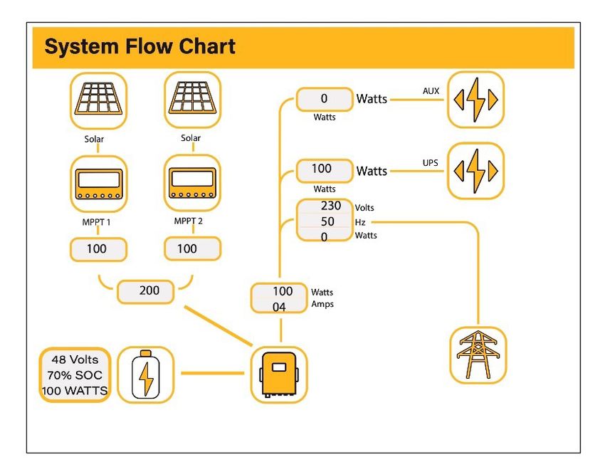
5.5. System Flow Page
Access by clicking on the bar chart on the Home Page.
To better understand the functioning of your system, take a look at the figure bellow:
1. The PV modules charge the batteries.
2. When the batteries reach a specific level (programmable) the battery power is fed into the
inverter.
3. The inverter can then supply power to the grid (export or no export), load, and auxiliary or
smart load.
4. CT coil controls the export power.
What this page displays:
The system flow.
MPPTs power.
Battery status.
Power distribution to load or grid.
Hybrid Inverter | Installer Manual Page | 425.6. Setup Page
To access the Settings, click on the gear icon on the right top of the navigation menu.
What this page displays:
Serial number.
Software version.
Time, Date, and MCU.
What you can do from this page:
Access the Basic Setup Page (press the BASIC icon).
Access the Battery Setup Page (press the BATTERY icon).
Access the Grid Setup Page (press the GRID icon).
Access the real-time programmable timer/system mode (press the SYSTEM MODE icon).
Access the advanced settings such as Paralleling and Wind Turbine (press the ADVANCE
icon).
Access the auxiliary load/smart load settings (press the AUX LOAD icon)
Access the fault code register (press the FAULT CODES icon).
Set up Li BMS (press the LI BMS icon).
5.7. Set Time (Clock)
To set time, click on the BASIC icon and then on ‘Time’
What this page displays:
Time.
Date.
AM/PM.
What you can do from this page:
Adjust / set time.
Adjust / set date.
Adjust / set AM/PM.
How to set up:
1. Touch the screen on the box you wish to change.
2. Change the number (increase/decrease) using the UP and DOWN buttons.
3. Press OK to set the changes.
Page | 43 Hybrid Inverter | Installer Manual5.8. Set Company Name / Beeper / Auto dim
To set company name click on the BASIC icon and then on ‘Display’.
What this page displays:
Beeper status (ON/OFF).
Installers names.
What you can do from this page:
Set up your company name.
Switch the beeper ON or OFF.
Set the LCD backlight to auto dim
How to change the name:
Change the letters in each box by mov-
ing the arrows up and down and then
85%
select OK. This will change the name
on the home screen.
SOLAR/TURBINE AC load
0.0 0.0 0.0 0.0 0.0 0.0
kWh kWh kWh kWh kWh kWh
BATTERY IN/OUT MPPT. GRID. Battery Grid
How to set the auto dim:
Set a number in the auto dim box to
dim the LCD after a number of sec-
onds.
How to turn the beep on or off:
Mark or unmark the beep box and the
press OK to configure it as you prefer.
Hybrid Inverter | Installer Manual Page | 445.9. Factory Reset and Lock Code
To access the Settings, click on the gear icon on the right top of the navigation menu.
What this page displays:
Reset status.
Whehter the ‘lock code’ is used or
not.
What you can do from this page:
Reset the inverter to the factory set-
tings.
System diagnostics.
Change or set the ‘lock code’.
What you can do from this page:
Factory Reset: Reset all parameters of the inverter
Lock out all changes: Enable this menu to set parameters that before the unit is locked and
cannot be reset.
*Before performing a successful ‘Factory Reset’ and locking the systems the user
must enter a password to allow the setting to take place. The password for ‘Factory
Reset’ is 9999 and for lock out is 7777.
System self-check: Allows the user to conduct a system diagnosis.
Test mode (only for engineers): For engineers to conduct tests.
Page | 45 Hybrid Inverter | Installer Manual5.10. Battery Setup Page To configure battery settings, click on the BATTERY icon and then on ‘Batt type’. What this page displays: Battery capacity in (Ah) – For non-BMS-batteries the range allowed is 0-2000Ah, while for lithium-ion the inverter will user the capacity value of the BMS. Max battery charge current (Amps). Max battery discharge current (Amps), which should be 20% of the Ah rating for AGM only. For Lithium, please refer to the battery manufacturer documentation. Note: This is a global max. discharge current for both ‘grid-tied’ and ‘backup’ modes of operation and if the cur- rent exceeds this value inverter will shut down with an overload fault. TEMPCO settings - Temperature coefficient is the error introduced by a change in tempera- ture. What you can do from this page: Use battery voltage for all settings (V). Use battery SOC for all settings (%). No battery: tick this box if no battery is connected to the system. BMS setting. Active battery - This feature will help recover a battery that is 100% discharged by slowly changing from the solar array. Until the battery reaches a point where it can change normally. Hybrid Inverter | Installer Manual Page | 46
5.11. Generator & Battery Page To configure battery charging settings, click on the BATTERY icon and then on ‘Batt Charge’. What this page displays: Generator start voltage/SOC %. Grid power start voltage/SOC %. Float V is the voltage at which a battery is maintained after being fully charged. Absorption V the level of charge that can be applied without overheating the battery. Float V for an AGM battery is 55.20V. Absorption V is for an AGM battery is 57.60V. Equalization V for an AGM battery is 58.80V. Equalizing charge/overcharge to remove sulphate crystals that build-up on the plates over time on lead-acid batteries. What you can do from this page: Tick ‘Gen Charge’ to charge the batteries from the gen I/P. Tick ‘Grid Charge’ to charge the batteries from the grid I/P. Tick ‘Gen Signal’ signal to auto-switch a relay box. Tick ‘Grid Signal’ signal to auto-switch a relay box. Do not alter these settings too many times on the same battery as it may damage the battery. Page | 47 Hybrid Inverter | Installer Manual
Gen Charge: Uses the GEN input of the system to charge battery bank from an attached gen-
erator.
Gen Signal: Normally open (NO) relay that closes when the Gen Start signal state is active.
Gen Max Run Time: This indicates the longest time the generator can run in one day. When the
maximum running time is reached, the generator will be turned off. ‘24H’ means the generator
will run continuously.
Gen Down Time: This indicates the delay-time of the generator to shut down after it has
reached the running time
Grid Charge: It indicates that the grid will charge the battery.
Grid Signal: Indicates when the grid should no longer charge the battery.

Recommended battery settings:

Battery Type       Absorption Stage         Float Stage            Voltage (every 30 days 3hr)
AGM (or PCC)          14.2V (57.6V)        13.4V (53.6V)                  14.2V (57.6V)
Gel                   14.1V (56.4V)        13.5V (54.0V)
Wet                   14.7V (59.0V)        13.7V (55.0V)                  14.7V (59.0V)
Lithium                                Follow its BMS voltage parameters

A generator can either be connected to the Grid side or to the Gen connection. When connect-
ed to the Grid Input, the inverter will consider the power coming from the generator as ‘Grid
Supply’. Users should make sure this power goes to the LOAD only and should not be exported
to other outlets as this will damage the generator.
An advantage from connecting the generator to the Grid Input is is that it can be paralleled
whereas the GEN/AUX input cannot be paralleled. That means the inverter will extract what
power it requires from ‘Grid Supply’ to charge its batteries.
If the generator is connected to the inverter and a generating signal exists, the inverter will
switch 100% of the load to the generator and then slowly increase the charging currents to the
batteries. Therefore, the generator must be able to supply both the charge current and the total
load current.
The generator can be controlled via a relay which has a set of dry-contacts to enable remote
control. The current on thee contacts is limited to approximately, 1Amp 12V.
Below is a simple reference circuit of an auto start system that can autostart generators on a
boat. (Sunsynk will be releasing a new OS E406 ( Auto-Start ) for better generator control)

Hybrid Inverter | Installer Manual                                                 Page | 48
Page | 49 Hybrid Inverter | Installer Manual
5.12. Battery Discharge Page To configure inverter’s shutdown settings, click on the BATTERY icon and then on ‘Shut Down’. What this page displays: Inverter shutdown voltage set as either a voltage or %. Inverter low battery warning set as either a voltage or %. Restart voltage set as either a voltage or %. What you can do from this page: Adjust battery shut down (voltage or %) Adjust low battery warning (voltage or %) Adjust restart (voltage or %) Activating Shutdown causes the inverter to enter standby-mode. It does not com- pletely shut down the inverter. Total shutdown occurs at voltages below 19V. The voltage displayed on the Sunsynk Parity Inverter will vary depending on whether the inverter is charging or discharging the batteries. Hybrid Inverter | Installer Manual Page | 50
Since the batteries are 48V the figure on the left is x4:
Fully Charged 50.54V (Discharge Mode)
Fully Charged 58.50V (Charge Mode)
75% Charged 49.60V (Discharge Mode)
75% Charged 54.80V (Charge Mode)
25% Charged 48.00V (Discharge Mode)
25% Charged 50.80V (Charge Mode)
Completely Discharged 47.50V
Setting the cut-off higher is better for the batteries.
The batteries recommended for use with the Sunsynk systems are AGM Lead Acid or Lithium
Battery Banks. (‘AGM’ means Absorbed Glass Matt construction that allows the electrolyte to
be suspended new the plate’s active material. In theory, this enhances both the discharge and
recharging efficiency. AGM batteries are very heavy as a result).
State of Charge
Bulk: Bulk charge is the first stage of a battery’s charging process where the charger identi-
fies the battery and its needs and then applies a high voltage to do the bulk of the charging. It
involves about 80% of the recharge. The properly sized charger will give the battery as much
current as it will accept up to charger capacity (25% of battery capacity in Amp hours).
Absorption: To fully charge a battery a period of charging at a relatively high voltage is needed.
This period of the charging process is called absorption. This occurs when the charging of a
battery has reached reached 80% of its capacity. The remaining charge equals 20% approxi-
mately. It makes the charger to hold the voltage at the charger’s absorption voltage (between
14.1 VDC and 14.8 VDC, depending on charger set points) and decreasing the current until the
battery is fully charged.
Float: The charging voltage is reduced to between 13.0 VDC and 13.8 VDC and held constant,
while the current is reduced to less than 1% of battery capacity. This mode can be used to
maintain a fully charged battery indefinitely.
Equalisation: This is essentially a controlled overcharge that occurs at the end of the Bulk
mode and the absorption phase and is called the ‘equalisation voltage’. However, this techni-
cally this phase has another function. Higher capacity wet (flooded) batteries sometimes benefit
from this procedure, particularly the physically tall batteries. The electrolyte in a wet battery can
stratify over time, if not cycled occasionally. In equalisation, the voltage is brought up above
typical peak charging voltage well into the gassing stage and maintained for a fixed (but limited)
period. This stirs up the chemistry in the entire battery, ‘equalising’ the strength of the electro-
lyte, and knocking off any loose sulphating that may be on the battery plates.
Page | 51 Hybrid Inverter | Installer Manual5.13. Setting Up a Lithium Battery To set up a lithium-ion battery, click on the BATTERY icon and visit the ‘Batt Type’ column. What this page displays: This information will only display if the ‘Lithium’ option is selected under ‘Batt Type’. The type of communion protocol. Approved batteries. What you can do from this page: Set up you Lithium-ion battery. After installing a lithium battery, check on the communications page by clicking on the ‘Li BMS’ icon to see if the BMS information is visible. If some information is not displayed correctly (it should look like the diagram below) then there will be a communication error. Hybrid Inverter | Installer Manual Page | 52
Therefore, if a communication error occurs:
1. Check that your data cable is the correct type.
2. Check that the data cable is plugged into the correct sockets. Usually, RS485 is employed,
but some battery manufacturers use others.
With some types of lithium battery, the BMS cannot be controlled by the Sunsynk
inverter. In this case, treat the battery as a lead-acid type and set the charging and
discharging protocol following the battery manufacturer specification.
It is important to refer to the manuals that manufacturers produce for their batteries. That way,
the chance of errors occurring during installation are greatly reduced. Below there is a list of
batteries that has been examined, tested, and approved by Sunsynk.
48V
RS485 Inverter
Brand Model Storage Notes
or CAN Setup
Inverter
CAN 0
US2000B
RS485 12
CAN 0
US3000
RS485 12
CAN 0
US2000C
RS485 12
CAN 0
US3000C
RS485 12
PYLON
CAN 0
UP5000
RS485 12
CAN 0
US5000
RS485 12
CAN 0
Force L1
RS485 12
CAN 0
Force L2
RS485 12
B4850 0
DYNESS CAN
POWERBOXF 0
SS4074 0 To be used with V2 Log-
SS4037 0 ger http://solarmd.co.za/
SolarMD CAN inverter-compatibility-so-
SS202 0 larmd/ sunsynk-and-so-
lar-md/
SHOTO SDC10-Box 5 CAN 0
Page | 53 Hybrid Inverter | Installer Manual48V
RS485 Inverter
Brand Model Storage Notes
or CAN Setup
Inverter
HUBBLE AM-2 5.5KW CAN 0
SSIF2P15S48100C RS485 1
SACRED
FCIFP48100A RS485 1 Cut Line 3, 6, 8
SUN
SSIFP48100A RS485 1
UZ ENERGY UZ-EB51.2-100ALL CAN 0
ESS-5120 RS485 6
ESS-10240 RS485 6
GenixGreen ESS-BOX2 RS485 6
ESS-BOX3 RS485 6
ESS-BOX4 RS485 6
Sunwoda H4850M RS485 7
V-LFP51.2V100Ah-5KW CAN 13
VISION Group
VLFP51.2V200Ah-5KW CAN 13
M4856-P CAN 0
Alpha Ess
SMILE BAT CAN 0
GSL051100A-B-GBP2 CAN 0
GSL051200A-B-GBP2 CAN 0
GSL ENER- GSL051280A-B-GBP2 CAN 0
GY ZnP48100ESA1 CAN 0
ys GSL-51-100 CAN 0
GSL-51-200 CAN 0
TB51100F-T110 CAN 0
TOPBAND
TB51120-T110 CAN 0
4K4 LV CAN 0
Weco
5K3 LV CAN 0
IPACK CAN 0
DOWELL C3.3/IPACK CAN 0
C6.5/IPACK C10 CAN 0
G2500-48V CAN 0
Giter
G5040-48V CAN 0
CFE2400 CAN 0
CF Energy CFE5100 CAN 0
CFE5100S CAN 0
Batterich/
UP3686 CAN 0
Greenrich
BYD Battery-Box LV
BYD CAN 0
Flex Lite
Hybrid Inverter | Installer Manual Page | 5448V
RS485 Inverter
Brand Model Storage Notes
or CAN Setup
Inverter
RJ45 Pin 1: GND
48NPFC80 RS485 16 RJ45 Pin 2: RS485_A
RJ45 Pin 3: RS485_B
48NPFC100 RS485 16 RJ45 Pins 4, 5, 6, 7, 8:
No Connection
Narada
Single-phase Hybrid
48NPFC150 RS485 16 Inverter Comm version
is E41E Single-phase
48NPFC200 RS485 16 Hybrid Inverter Comm
version is 1001 - E016
SUNB-5.0-C01-48-PC CAN 0
Deye SUNB-5.0-E01-48-PC CAN 0
SUNB-5.0-G01-48-PC CAN 0
Uhome-LFP 5000 CAN 0
AOBOET
Uhome-LFP 2400 CAN 0
Wattsonic Li-LV battery series CAN 14
KODAK FL5.2 CAN 0
Fox ess LD-48100P RS485 1
PYTES
E-BOX 48100R CAN 0
Energy
BST MD48-100 CAN 0
MD48-50 CAN 0
Highstart HSD4870 CAN 0
Rosen Solar
LFP48V200AH CAN 0
Energy
ZR-FC48100-1630J1 CAN 0
ZR-FS4850-16OSJ1 CAN 0
ZRGP
ZR-FS48100-16OSJ1 CAN 0
ZR-PBX1 CAN 0
P26 CAN 0
BALANCELL
P27 CAN 0
Shanghai GTEM-48V2500
Green RS485 12
Tech Co.,Ltd.
Unipower UPI.FP4845 RS485 15
LD LD-100P210J RS485 17
Page | 55 Hybrid Inverter | Installer ManualWhen communications between battery and inverter does not exist, do not over- charge your battery bank (current or voltage). Many lithium batteries are limited to 100A, some are lower and some are higher. Ensure that voltage and current speci- fications provided by the battery manufacturer are followed. If you are using lead acid batteries then follow the equation of C x 0.25 which means that the maximum charge or discharge you can apply to a battery is a quarter of the AH rating of the overall battery array. E.g: A 200Ah battery array composed of 4 x 200Ah batteries in series has a maximum discharge of only 50Ah (200 x 0.25 = 50) Also, ensure the cable is thick enough to support the current and the fuses con- nected are of the correct rating as per the recommendations of battery manufac- turers. Hybrid Inverter | Installer Manual Page | 56
5.14. Program Charge & Discharge Times To set ‘Charge’ and ‘Discharge’ times, click on the ‘System Mode’ icon after clicking on the gear icon. What this page displays: A setting to prevent the inverter exporting power to the grid - ‘Zero Export’. The ability to limit power supply to only the household loads - ‘Solar Export’. Set the power limits to supply only the loads connected to the LOAD port - ‘Priority to Load Only’. What you can do from this page: Set a real time to start and stop charging or discharging the battery. Choose to charge the battery from the grid or generator. Limit export power to the grid. Set the unit to charge the battery from the grid or generator ticking ‘Grid’ or ‘Gen’ and set what times this needs to occur. Set the time to discharge the unit to the load or export to the grid by unticking ‘Grid’ and ‘Gen’. Page | 57 Hybrid Inverter | Installer Manual
Concerning the detailed figures above:
1. Tick this box to do not export power back to the grid (the CT coil will detect power flowing
   back to the grid and will reduce the power of the inverter only to supply the local load).
2. Tick this box if you wish to export your solar power back to the grid.
3. Tick this box if you only want to supply power to the load side of the inverter.
4. ‘Zero Export Power’ is the amount of power flowing from the Grid to the Inverter. Set this
   value to ’20 - 100W’ to instruct the inverter to always take the prescribed amount of pow-
   er from the Grid to minimise the tripping of sensitive pre-paid electricity meters if ‘Reverse
   Power Detection’ occurs.
5. This controls the maximum overall power, both to the ‘Load’ and ‘Grid’ ports combined. It
   is set to Low if an ‘over-current’ fault occurs
6. Tick this box if you wish to set the solar panels give power to the ‘Load’. If you untick this
   box the solar will send power to charge the batteries.

Hybrid Inverter | Installer Manual                                                Page | 58
Example:
This example shows the battery being charged up to 100% by both the Grid and Solar PV from
8 a.m. to 11 a.m. and then being able to supply up to 4kW of battery-power to the ‘essential’
loads from the ‘Load’ Port until the battery SOC drops to 50%.

IMPORTANT - When charging the batteries from the Grid or Generator, please ensure you
have set the correct battery-charging settings on the battery charge as shown in Section 4.10
‘Battery Setup’ Home Page. If the ‘Use Timer’ function is activated then the inverter will use the
battery power according to your settings when the Grid is present. If this function is not set, the
batteries WILL ONLY be used for backup when there is no utility grid power.

Example:
The power produced is supplying the ‘Non-Essential Load’ while the inverter is set at a max-
imum power of 8kW (Max Sell Power). The inverter is connected to the grid, but no export is
performed. The unit allows small amounts of power to flow from the Grid (100W Zero Export
Power) to prevent any back-flow. In this example, the solar PV is prioritised to supply the Load
first and then subsequently, charge the battery.

Page | 59                                                  Hybrid Inverter | Installer Manual
5.15. Grid Supply Page On the Settings Menu, click on the GRID icon. What this page displays: Grid frequency setting. Grid type (normally 230V three-phase). What you can do from this page: Set the Minimum Grid Input Voltage (‘Grid Vol Low’). Set the Maximum Grid Frequency (‘Grid Hz High’). Set the Minimum Grid Frequency (‘Grid Hz Low). Select the correct Grid Type in your local area, otherwise the machine will not work or be damaged. Select the correct Grid Frequency in your local area. Hybrid Inverter | Installer Manual Page | 60
You can also read