Home Location and Approach 01 - Centre for ...
←
→
Page content transcription
If your browser does not render page correctly, please read the page content below
Centre for Excellence in Universal Design

Home Location
and Approach
01

     UD Home Guidance                 Houses

  X UD Home Plus Guidance             Apartments

Universal Design Homes should be appropriate to their context
and create a strong sense of place. Attention to detail and high
quality materials are essential to ensure longevity of use. Well-
designed housing will be appreciated and treated well by the
people who live there.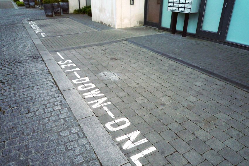
Universal Design Guidelines For Homes in Ireland

1.1 Location

01   02    03    04   05    06   07    08    09    10   11   12   13   14   15   16   17   18   19   20   21

Landscaping
 01 02 03 and
            04approach
                05 06 path
                        07 to 08
                              housing
                                  09 development.
                                      10   11 12                  13   14   15   16   17   18   19   20   21
Photo Design Features
01    02   03    04   05    06   07    08    09    10   11   12   13   14   15   16   17   18   19   20   21
PPDistinctive character to housing and external environment.
01 A 02
P    wide 03
           pavement
               04 05 is provided,
                          06 07 at08least092000mm
                                              10 11clear
                                                      12 width.
                                                            13  14  15     16         17   18   19   20   21

P Light fittings do not reduce the width of pavement.
P Clear colour contrast between path and planting.
P Open views not obscured by planting – foliage kept to low or high level.
P Semi-public realm well overlooked.
Photo Design Tip
  R Gravel is difficult for many people to use, particularly those using strollers,
    wheelchairs, walking sticks or crutches.

22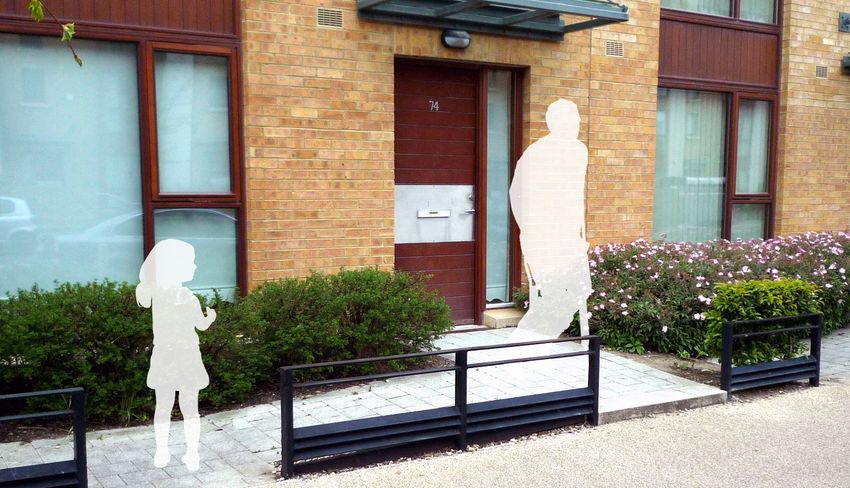
Home Location and Approach: Section 01

01   02   03   04   05   06   07   08   09   10   11   12   13   14   15   16   17   18   19   20   21   22   23   24   2

01   The
      02 development
          03 04 05 creates
                       06 07 a 08
                                new 09street
                                          10 off11an existing
                                                      12   13 busy
                                                               14  15      16   17   18   19   20   21   22   23   24   2
     thoroughfare in the town centre.
01   02   03   04   05   06   07   08   09   10   11   12   13   14   15   16   17   18   19   20   21   22   23   24   2
     Development Sites for New Homes
01   02   03   04   05   06   07   08   09   10   11   12   13   14   15   16   17   18   19   20   21   22   23   24   2
     Design Considerations and Awareness
     It is important that development sites be selected on the basis of the quality
     of the environment which exists or can be created around the new homes. A
     development site should be well-connected locally, with easy access to transport
     links and places to socialise and shop. The development should enhance the
     existing local identity and be a desirable place for everyone to live.

     Consider site features that could provide a challenge to some people in the
     community. For example, steeply sloping sites are difficult for walking, cycling,
     pulling luggage, pushing a buggy, a wheelchair, or for toddlers, people with
     breathing or heart conditions.

     UD Home • and UD Home X Guidance
     •• Ensure that large schemes include, or are close to, public amenity space,
        with good access to transport and local shops, pubs and cafes.

     •• Avoid steeply sloping sites, or factor in from the outset how to ensure that
        gradients do not compromise accessibility when developed.

     •• On large sites with a gradient between 1:60 and 1:25, provide regular
        resting places for people.

     •• Provide regular resting places on sloping sites, at every 19m maximum,
        for gradients of 1:25, and at every 25m maximum for gradients of 1:33.
        An access route steeper than 1:25 should be designed as a ramp.

     XX Consider provision of WiFi and mobile applications to further enhance
          accessibility and provide useful local information for everyone.

     23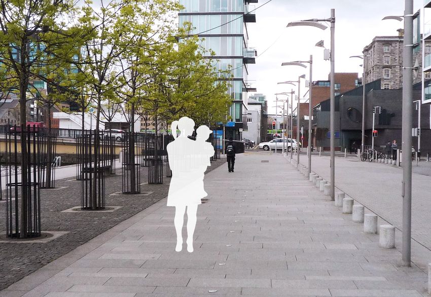
Universal Design Guidelines For Homes in Ireland

01   02   03   04    05   06   07   08   09    10   11   12   13   14   15   16   17   18   19   20   21   22   23   24

01   02 Sufficient
         03 04 05  space
                       06is provided
                             07 08 for09 all10users
                                                 11 to 12
                                                       pass,13with14clear
                                                                       15 differentiation
                                                                             16   17   18 between
                                                                                            19 20 21       22   23   24
        traffic and pedestrian areas. Bollards, light fittings and trees are kept within a defined
01   02 zone
         03 04 and do
                   05 not
                       06 interrupt
                             07 08the09pavement
                                            10   11 width.
                                                       12   13    14   15    16   17   18   19 20 21       22   23   24

01   02   Roads,
          03 04 05Streets and
                    06 07 08 09 Pavements
                                 10 11 12 13                       14   15   16   17   18   19   20   21   22   23   24

          Design Considerations and Awareness
          The layout of the buildings, roads and streets, and position of signage in a new
          development should make it easy for everyone to find their way around. All new
          roads and streets should link well with existing roads in the neighbourhood, and
          there should be a clear hierarchy from the main circulation road to smaller streets.
          All routes should be pedestrian, cycle, and vehicle friendly, and well overlooked
          to provide passive surveillance. Provide wide pavements, where people can pass
          easily, for example when using walking aids or pushing a buggy.

          To make the route comfortable for everyone, avoid placing obstacles such as trees,
          bins, bollards, lighting columns and signs in the clear footpath area. Ensure that
          inserts for services such as manholes or drains are level with the paving and that
          bicycles or wheels of prams cannot get stuck, and high heels or walking aids don’t
          get trapped. Design the pavement with cross-falls to prevent water ponding after
          rain. This avoids slippery surfaces, a reflective glare, or ice being formed.

          Select paving materials that are hard and firm, with non-slip and non-reflective
          properties as these are comfortable and safe for everyone. Surfaces like cobbles,
          bare earth, loose gravel and sand are difficult to walk on for most people especially
          those using walking sticks or crutches, wheelchairs, bicycles, infant buggies and
          wheeled luggage. Colour contrast on pavements, for example in a pattern, can
          cause confusion for people with visual or cognitive difficulties. However, contrast
          colour can be used for kerbs, to indicate the edge of the pavement, assisting those
          with visual or cognitive difficulties. Consider the ease of making repairs at a later
          date, as replacement of sections in a different colour may also cause confusion.

          24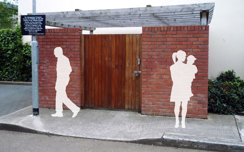
Home Location and Approach: Section 01

               Shared surfaces should use contrasting colour and surface textures to make the
               area easier to understand and safer for everyone. If there is a level change beside
               a pavement higher than a standard kerb drop to a roadway, provide protection to
               indicate the level change for safety. Tactile paving is essential for people with visual
               difficulties, for example to indicate where a dropped kerb or zebra crossing is located.

01   02   03   04    05   06   07   08    09   10    11   12   13   14    15   16   17    18   19   20    21   22   23   24

               The parking area is clearly designated as a shared surface area.
01   02   03   04   05    06   07   08    09   10    11   12   13   14    15   16   17    18   19   20    21   22   23   24
               Photo Design Tip
01   02   03   04 05 06 07 08 09 10               11   12   13   14  15   16    17        18   19   20    21   22   23   24
                 R More design features to signal the designation would ideally
                   have been included, such as trees and carriageway narrowing.
01   02   03   04    05   06   07   08    09   10    11   12   13   14    15   16   17    18   19   20    21   22   23   24

               UD Home • and UD Home X Guidance
               •• Provide a clear hierarchy of streets that is logical, easy to understand and
                  well integrated with the existing context.

               •• Install street signs at the head of T-junctions, so that visitors can identify
                  easily where they are.

               •• Design pavements with a minimum width of 2000mm, narrowing only to
                  1800mm where unavoidable for electric junction boxes, etc..

               XX Design pavements with a minimum width of 2400mm, narrowing only to
                    2000mm where unavoidable for electric junction boxes, etc..

               •• Ensure that pavements are kept clear of obstructions.

               25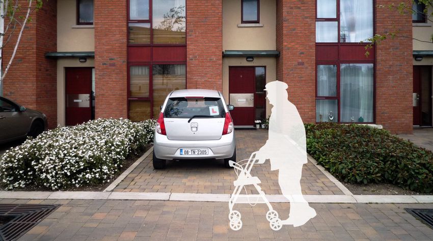
Universal Design Guidelines For Homes in Ireland

•• Ensure that the surface materials specified are appropriately non-slip with a
   dry friction coefficient between 35 and 45.

•• Specify materials which are non-reflective.

• Ensure materials can be replaced and repaired easily and quickly.

•• Ensure that kerbs are installed on pavements.

• Provide kerbs in a contrast colour to the footpath paving for good visibility.

• Install dropped kerbs at all junctions, matched on each side of the road.

• Provide kerb upstands, barriers or guardrails where there is a change of level
  beside the pavement higher than a kerb.

• Avoid the use of cobbles, sand or gravel for pavements.

• Ensure that any breaks in paving are maximum 10mm wide and perpendicular
  to the direction of movement.

•• Ensure that any insert, whether for an inspection chamber, gully or similar, is
   level with the paving.

• Design pavements with a cross-fall gradient not exceeding 1:50, except where
  there is a dropped kerb.

UD Home XX Guidance
Consider providing pavements of minimum width 2400mm for the full length of
the pavement without interruptions.

26
Home Location and Approach: Section 01
1 02 03 04 05 06 07 08 09 10 11 12 13 14 15 16 17 18 19 20 21 22 23 24 25
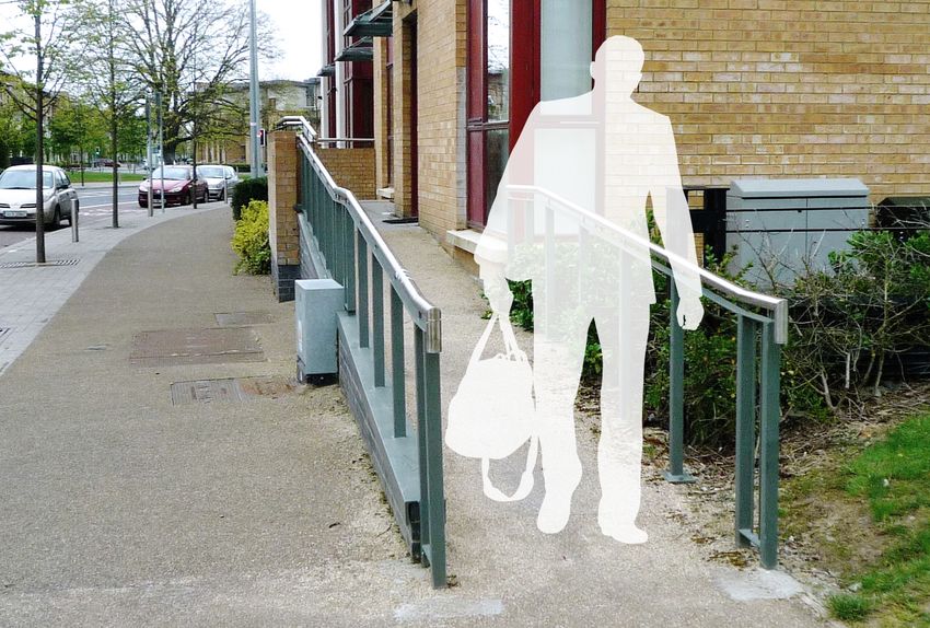
1 02 03 04 Access
05 06path
07is well-lit
08 09 and 10
lighting
11 does
12 not
13 obstruct
14 15the 16
clear17width.
18 19 20 21 22 23 24 25
1 02 03 04
Photo Design Tip
05 06 07 08 09 10 11 12 13 14 15 16 17 18 19 20 21 22 23 24 25
R The tactile surface should cover the dropped kerb area but not the
1 02 03 04 05 radiused
06 07 corner.
08 09 10 11 12 13 14 15 16 17 18 19 20 21 22 23 24 25
Street Furniture and Lighting
Design Considerations and Awareness
Co-ordination of street furniture such as sign-age, lighting, junction boxes, seats,
litter bins and parking meters, as well as planting, should ensure that a clear and wide
enough route for all is provided. The design of street furniture should be co-ordinated
and incorporate colour or tonal contrast with its surroundings for good visibility.
Bollards should be very easy for everyone to see and should never be linked by chains.
Wherever possible all street furniture, such as litter bins and signage between columns,
should be the full width down to ground level to allow people with visual difficulties to
understand the full dimensions at ground level with a mobility cane.
Good lighting design should provide even illumination along a street, sufficient for
everyone to feel safe and move around easily at dusk and night time. Lighting should
make it easy to locate entrances and identify front door numbers and signage.
For lighting levels, please refer to section 4.
27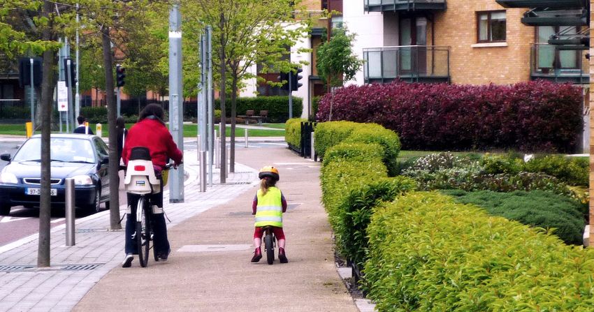
Universal Design Guidelines For Homes in Ireland

02   03   04   05   06    07   08    09    10   11    12   13    14    15   16   17   18   19   20   21   22   23   24   25   26

02   03   04   05
                    Broad  footpaths that are clear
                    06 07 08 09 10              11
                                                    of
                                                    12
                                                       obstacles,
                                                         13   14
                                                                  with
                                                                    15
                                                                       indicators
                                                                          16   17
                                                                                  of 18
                                                                                      the location
                                                                                           19 20     21   22   23   24   25   26
                    of the road using tactile surfaces and bollards.
02   03   04   05   06 07Design
                    Photo   08 Tip
                                09         10   11    12   13    14    15   16   17   18   19   20   21   22   23   24   25   26

02   03   04   05   06R
                          The  tactile surface should
                           07 08 09 10           11
                                                      cover
                                                     12   13
                                                             the14
                                                                 dropped
                                                                     15
                                                                         kerb 17
                                                                         16
                                                                              area but
                                                                                   18
                                                                                       not
                                                                                        19      20   21   22   23   24   25   26
                          the radiused corner.
                          The bollards should be highlighted, for example by using paint
                          or a reflective strip.

                    UD Home • and UD Home X Guidance
                    •• Ensure that street furniture layout is co-ordinated and consistent.

                    • Highlight bollards by means of a light or contrast colour at the top,
                      and do not link with chains.

                    • Avoid installing letter boxes, litter bins and telephones on pedestals
                      because they may confuse and cause accidents to people with visual
                      difficulties using a mobility cane.

                    • If eye-level signs are not taken down to ground level, ensure that there is
                      a tapping rail between posts at 250 to 400mm above ground level, with
                      posts and rail contrasting visually with the background.

                    28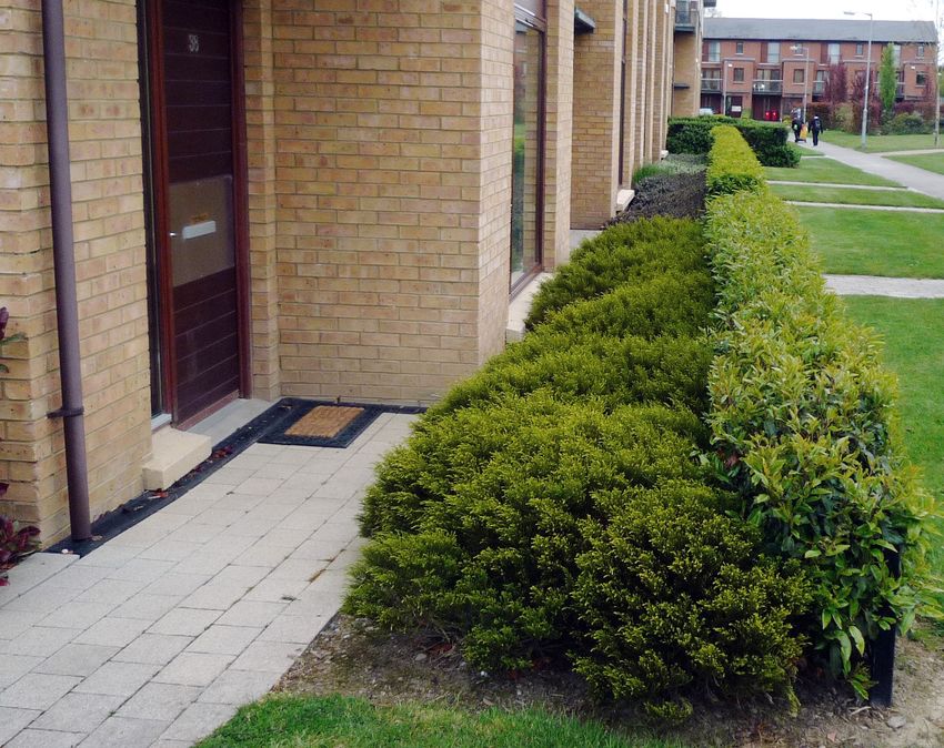
Home Location and Approach: Section 01

• Ensure that eye-level signs do not extend more than 150mm beyond the posts.

•• Ensure that suspended signs are above head height for tall people and
   cyclists, at 2300mm minimum.

• Highlight free-standing posts and columns with a 150mm–high feature, such
  as a visually contrasting crest or band 1500mm above ground level.

• Locate lighting columns at the back edge of the pavement where possible.

     • Lighting columns may be mounted on buildings or walls wherever possible to
       keep pavements clear of obstacles.

•• Locate lighting columns and any other signage posts at least 1000mm apart.

29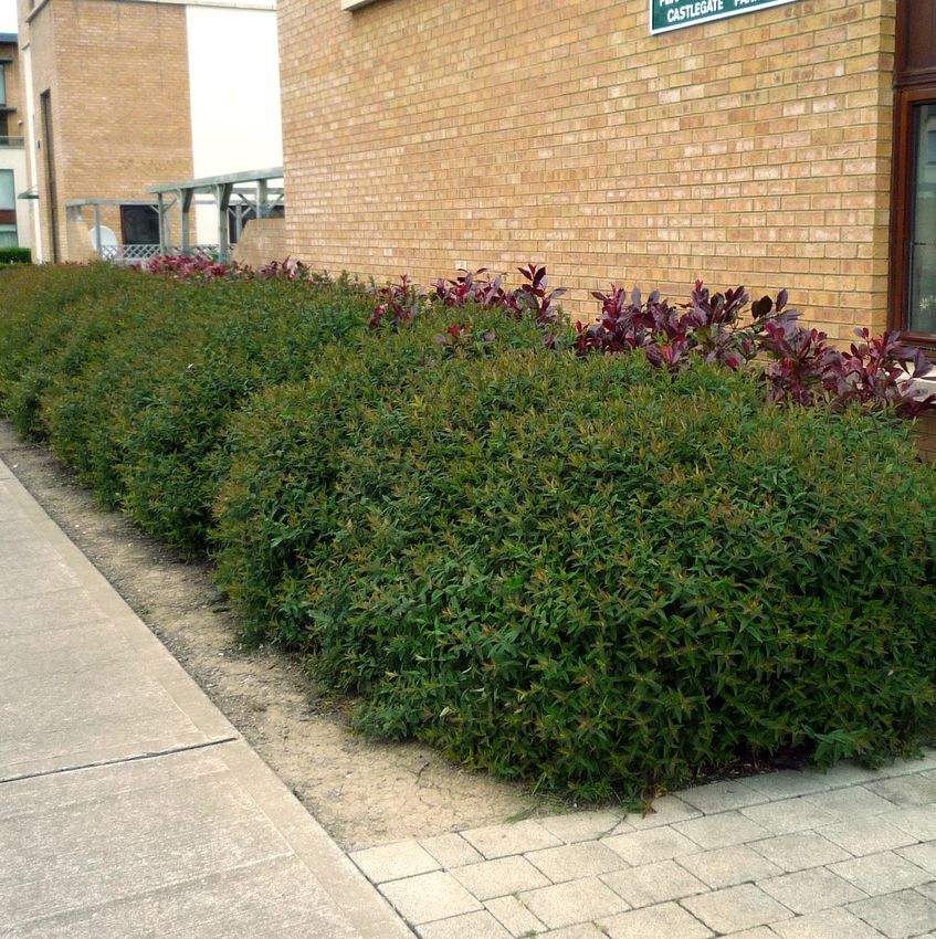
Universal Design Guidelines For Homes in Ireland

                    1.2 Approaching the Home

02   03   04   05   06         07   08    09    10   11    12   13    14   15    16   17    18   19    20   21    22     23   24   25   2

02   03   04   05 Terraced
                   06 07 housing.
                           08 09               10    11    12   13    14   15    16   17    18   19    20   21    22     23   24   25   2

                    Photo Design Features
02   03   04   05   06         07   08    09    10   11    12   13    14   15    16   17    18   19    20   21    22     23   24   25   2
                             P Level access provided from pavement.
02   03   04   05   06 Parking
                         07 08 space
                                  09 allows
                                        10 for
                                            11 car12door
                                                       13 opening
                                                            14   15and 16
                                                                       is adjacent
                                                                            17   18to path.
                                                                                      19 20                 21    22     23   24   25   2
                             Firm, non-slip, non-reflective surfaces.
                             Planting and materials define boundaries clearly.
                             Public realm is well overlooked.
                             Consistency in design with no unit standing out.
                             A canopy is provided above each front door.
                    Photo Design Tip
                         R    Tree reduces pavement clear width locally.
                              There is a lack of planting for visual interest, distinctiveness, and privacy screening.

                    30
Home Location and Approach: Section 01
4 05 06 07 08 09 10 11 12 13 14 15 16 17 18 19 20 21 22 23 24 25 26 27 28
4 05 06 07 A08mix09
of house
10 typologies
11 12 and 14
13 tenures
15 is 16
provided.
17 18 19 20 21 22 23 24 25 26 27 28
4 05 06 07 Appearance
08 09 10 11 of
12 the
13 Home
14 15 16 17 18 19 20 21 22 23 24 25 26 27 28
4 05 06 07 Design
08 09 Considerations
10 11 12 and
13 Awareness
14 15 16 17 18 19 20 21 22 23 24 25 26 27 28
There should be a range of home sizes, types and tenures in every residential area.
A mix of family homes and smaller apartments provides moving-on
accommodation when it is required, as well as a mixed population which will
reflect the make-up of society. It is important to ensure that vulnerable groups in
society are not targeted by anti-social behaviour. Therefore the overall external
appearance of UD Homes that might be adapted to particular needs should be
consistent with neighbouring homes, and should be integrated across the site and
not grouped together in one area alone.
Where there are many houses of consistent design it is also important to make it
easy for everyone to locate a home, for example by using distinctive design features
such as door colours, boundary treatments, planting, porch canopy details etc.
UD Home • and UD Home X Guidance
•• Ensure that all homes are designed to a high standard and of good quality,
using sustainable materials with quality detailing.
• Ensure that there is a mix of tenures and home sizes in every development of
20 homes or more.
• Ensure that UD homes that might be adapted to particular needs are
consistent with neighbouring homes, and not constrained to one part of a site,
or grouped together.
• Ensure that each UD home has potential to be distinctive through
individualised design features such as door colours or planting.
31Universal Design Guidelines For Homes in Ireland
05 06 07 08 09 10 11 12 13 14 15 16 17 18 19 20 21 22 23 24 25 26 27 28 2
Designated parking spaces with 1200mm access zone located close to communal
05 06 07 08 09 10 11 12 13 14 15 16 17 18 19 20 21 22 23 24 25 26 27 28 29
entrance and integrated into the design of the street.
05 06 07 08 09 10 11 12 13 14 15 16 17 18 19 20 21 22 23 24 25 26 27 28 2
Setting-down Points and Communal Parking
05 06 07 08 09 10 11 12 13 14 15 16 17 18 19 20 21 22 23 24 25 26 27 28 2
Design Considerations and Awareness
Providing a clearly identified set-down point close to the entrance of any housing
complex can benefit everyone. For example, it can make it easier to deliver
groceries, and to help young children or older people out of a car, especially in
bad weather.
Generous parking spaces make life easier for everyone including people with
mobility difficulties, someone unloading shopping from a car, and young families
moving from the car to the home.
Depending on the size of car park, there should be at least one clearly marked
accessible parking bay with a 1200mm zone on both sides and at the rear located
near each communal entrance.
If underground parking is provided, some designated accessible parking bays
should be provided close to the lifts serving the apartments above.
5% of car parking spaces should be accessible and suitably located.
32Home Location and Approach: Section 01
06 07 08 09 10 11 12 13 14 15 16 17 18 19 20 21 22 23 24 25 26 27 28 29 30
06 07 08 09 Clear
10 11designation
12 13 of set-down
14 15 16 area
17 in
18 front
19 of
20the21entrance
22 23 24 25 26 27 28 29 30
with level surfaces for everyone to use and ensure there is a buffer zone.
06 07 08 09 10 11 12 13 14 15 16 17 18 19 20 21 22 23 24 25 26 27 28 29 30
UD Home • and UD Home X Guidance
06 07 08 09 10 11 12 13 14 15 16 17 18 19 20 21 22 23 24 25 26 27 28 29 30
•• Provide a setting-down point in close proximity to the main entrance in
addition to any designated car parking spaces, but only where these spaces
are not in front of the entrance.
• Ensure there is a buffer that protects pedestrians from opening vehicle doors
and allows easy access to the building’s entrance door.
X Provide a setting-down point in close proximity to the main entrance in
addition to any designated car parking spaces of at least 3600 × 6000mm.
• Provide a dropped kerb for ease of access onto the pavement.
• Provide signage to ensure that the setting-down point is easily located, and
not used for casual parking.
• Ensure that the setting-down point has a firm, level, even surface, clear of
manhole covers and gullies.
• Design the car parking so that it is well integrated into the streetscape and
does not dominate.
• Ensure parking is located no more than 25m from an apartment block, but
preferably much nearer.
• Ensure that the route between the designated car parking spaces and the
entrance to the apartments is accessible, understandable, well-lit and safe to use.
• Ensure head-on (perpendicular) parking bays are at least 2400 × 4800mm.
• Ensure parking bays which are parallel with the direction of travel are at least 2400
× 6100mm.
33Universal Design Guidelines For Homes in Ireland
Technical Sketch:
Car parking spaces with shared access space, and fully accessible space.
Accessible parking bay sign on post Dished kerb
Footpath Footpath
4800mm
4800mm
1200mm
2400mm 1200mm 2400mm
Carriageway
1200mm 2400mm 1200mm
Carriageway
•• Ensure that there is a minimum of one accessible parking space with a
1200mm zone to the sides and rear, located near each communal entrance
or lift serving the apartments above.
• Where space permits provide an extra space of 1200mm shared between two
bays to make getting in and out of a car easier for everyone.
• Design 5% of parking bays to 3000 × 6000mm.
X Provide sheltered parking spaces for electric wheelchairs, scooters, shop-
riders, tricycles, etc., located near to the main entrance of the building.
X Ensure that some of the communal parking spaces are provided with a
power socket for charging batteries etc.
UD Home XX Guidance
Consider providing:
• A canopy at the setting-down point with a clearance of 2600mm.
• Some parallel parking spaces at 7000mm long.
• At least one van space at 4800 × 8000mm.
• Some dedicated larger parking bays which are 4500 × 6000mm close
to a block of apartments.
34Home Location and Approach: Section 01
7 08 09 10 11 12 13 14 15 16 17 18 19 20 21 22 23 24 25 26 27 28 29 30
Footpath to front door located adjacent to parking space, creating a flexible space
7 08 09 10 11 12 13 14 15 16 17 18 19 20 21 22 23 24 25 26 27 28 29 30
for everyone to use.
7 08 09 10 11 12 13 14 15 16 17 18 19 20 21 22 23 24 25 26 27 28 29 30
Parking for Houses
7 08 09 10 11 12 13 14 15 16 17 18 19 20 21 22 23 24 25 26 27 28 29 30
Design Considerations and Awareness
For individual houses the car space should be the minimum standard bay size of
2400 x 4800mm, but with the ability to extend the width from 2400 to 3600mm.
This can be achieved by locating the footpath to the front door, or a planting bed
that could be adapted in the future, adjacent to the parking bay. On-plot parking
will also benefit from an electrical socket for charging an electric car or motorised
wheelchair, and for connecting a vacuum cleaner when cleaning the car.
Car parking design quality guidelines
•• Design on-plot parking for houses at a length of 4800mm and width
of 2400mm, extendable to 3600mm.
• Where garages are provided, ensure they have minimum internal
dimensions of 4200 × 5700mm.
• Provide a vehicle charging point at the entrance to the home. The power
socket should be installed at an operating height of between 800mm and
1100mm above ground level.
X Ensure that the vehicle charging point is sheltered for the comfort of the user.
35Universal Design Guidelines For Homes in Ireland
Technical Sketch:
On-plot parking provision beside path or planted bed.
4800mm
Home
Footpath
2400mm
1200mm
UD Home XX Guidance
Consider providing:
• A parking area of 3600 × 7000mm.
36Home Location and Approach: Section 01
8 09 10 11 12 13 14 15 16 17 18 19 20 21 22 23 24 25 26 27 28 29 30
The gate is in a logical position with a wide and firm path to the entrance door.
8 09 10 11 12 13 14 15 16 17 18 19 20 21 22 23 24 25 26 27 28 29 30
Design Tip
8 09 10 11 12 13 14 15 16 17 18 19 20 21 22 23 24 25 26 27 28 29 30
R The gate should be easier to identify within the fencing.
8 09 10 11 12 13 14 15 16 17 18 19 20 21 22 23 24 25 26 27 28 29 30
Gates and Paths (private and communal)
Design Considerations and Awareness
The gate should be located so that it is easily identified from the street or road.
Gates should be easy to use for everyone, regardless of their upper arm strength.
Adjust hinges so that the gate does not spring shut on someone pushing a buggy,
using a wheelchair, or carrying groceries. Ideally the path to the gate should be
extended in width on the latch side to make it easy to open and shut.
The design of paths from the property boundary to the entrance of the home is
similar to the design of street pavements generally. Paths need to accommodate
people passing with room for those with bikes, buggies or wheelchairs.
Lighting to paths from the entrance to the property boundary should be provided
for apartment blocks. This also applies to homes with long front gardens where the
light at the entrance door is insufficient for the whole length of path.
UD Home • and UD Home X Guidance
•• Ensure that pedestrian gates are at least 900mm wide,
and easy to open and shut.
X Ensure that pedestrian gates are at least 1000mm wide,
and easy to open and shut.
• Ensure that gates over 1200mm high are not solid.
37Universal Design Guidelines For Homes in Ireland
•• Provide wiring for future installation of assisted opening mechanism.
X Provide assisted opening mechanism for the gates from the outset.
X Extend width of the path to the gate by 500mm on the latch side of the
gate.
• Ensure that paving within the property boundary is firm,
non-slip and non-reflective.
• Provide cross-falls of 1:50 so that the path drains easily.
• Ensure that paving is permeable so that it does not pond in
wet weather, or contribute to overcharging local drains.
• Ensure that the path is completely clear of obstacles throughout its length.
• Design the pathway to individual houses at a minimum of 900mm wide,
and to communal entrances at 2000mm wide, with a minimum width of
1500mm where there are obstacles.
X Design the pathway to individual houses at a minimum of 1200mm wide,
and to communal entrances at 2000–2400mm wide.
• Provide switched or P.I.R. sensor lighting at each pathway entrance to an
apartment block, and to long front garden paths to houses.
38Home Location and Approach: Section 01
9 10 11 12 13 14 15 16 17 18 19 20 21 22 23 24 25 26 27 28 29 30
Ramp and landings provided to raised ground floor with handrails on both sides.
9 10 11 12 13 14 15 16 17 18 19 20 21 22 23 24 25 26 27 28 29 30
Photo Design Tip
9 10 11 12 13 14 15 16 17 18 19 20 21 22 23 24 25 26 27 28 29 30
A larger landing outside the front door will make it easier for everyone
R
9 10 11 12 13 to14manoeuvre
15 16 and
17 interact.
18 19 20 21 22 23 24 25 26 27 28 29 30
There is no guarding at the lower edge of the ramp on the right hand side and
there should be tactile paving at the base and top of each section of ramp.
There should be tactile warning surface indicators to the top and bottom of
each ramp section at communal entrances.
Steps should be provided as an alternative for ramps longer than 2000mm
and the ramp should be lit at night.
Consider addition of lower handrails for people of smaller stature and children.
Ramps and Landings
Design Considerations and Awareness
Ramps and steps are difficult for many people, such as wheelchair-users or someone
pushing a buggy, to negotiate. If absolutely unavoidable, ramps and landings need
to be fully integrated into the design of the home or apartment development, and
designed to look attractive and accessible for everyone. Steep gradients can be
difficult for everyone. Level landings provide resting places and the shallower the
slope, the longer the interval can be between landings. A maximum length of 10m
is allowable in any one stretch.
Wherever there is a level change beside the ramp there should be protection to
indicate the level change and avoid creating a hazard. The base of a guard rail or
barrier can be taken down to the level of the ramp. The protection should contrast
visually with the ramp surface.
39Universal Design Guidelines For Homes in Ireland
A slope may be difficult for some people with mobility difficulties, and some people
might prefer to walk a shorter distance, and use steps instead. Steps should always be
provided in addition to a ramp.
If the rise of the ramp is 2000mm or higher, it is likely that the control needed to push
a wheelchair up, or control a descent, will be too great for the majority of people to
manage. Therefore an alternative means of access should be provided, such as a lift or
platform lift.
UD Home • and UD Home X Guidance
•• Avoid ramps and steps wherever possible.
• Any access gradient which is steeper than 1:25 should be designed as a ramp.
Refer to graph on page 41 for ramp gradients and distances.
• Ensure that ramp slopes are consistent and straight, not curved.
Change of direction can take place at a landing.
• Where unavoidable, design the ramp as an integral part of the
garden and building.
• Ensure that the width of the ramp is not less than the path it serves and:
• minimum 900mm wide ramp to individual houses.
• minimum 1500mm wide ramp to communal entrances.
XX Ensure that the width of the ramp is not less than the path it serves and:
• minimum 1500mm wide ramp to individual houses.
• minimum 1800mm wide ramp to communal entrances.
• Ramps of 1:20 or less are preferred for a distance of 10m; a slope of 1:12 is
allowable only for a distance up to 2m.
• Any ramp of 1:25 needs level landings at maximum 19m intervals. At a
gradient/slope of 1:33 provide landings at maximum 25m intervals.
• Provide a cross-fall of 1:50 maximum, sufficient to ensure good drainage of
the ramp and landing.
• Provide a minimum landing length of 1200mm for individual dwellings,
and 2000mm for communal buildings, clear of any door or gate swing.
X Provide a minimum landing length of 1500mm for individual dwellings
and 2400mm for communal buildings, clear of any door or gate swing. A
landing of 2400 x 2400mm is recommended for large apartment buildings
at the top and bottom of all ramps.
• Locate handrails on both sides of a ramp or steps (see section on Handrails).
• Continue the handrail around the landings.
40Home Location and Approach: Section 01
•• Provide protection that visually contrasts with the ramp ground surface
where there are level changes beside the ramp.
• Provide steps alongside any ramp that is more than 2000mm in length.
• Provide a corduroy tactile warning surface indicator (TWSi) at the top and
bottom of the flight of steps leading to communal buildings.
X Provide a corduroy tactile warning surface indicator (TWSi) at the top
and bottom of the flight of steps leading to private dwellings.
• Ensure that no ramp is greater than 2000mm in height. If it is, provide an
alternative means of access, such as a lift or platform lift.
• Provide lighting to ramps and landings to 150 lux.
UD Home XX Guidance
Consider providing:
• A minimum 1800mm wide ramp to individual houses.
• A minimum 2400mm wide ramp to a communal entrance.
• Landings of 2400mm length at the top and bottom of the ramp,
with intermediate landings of 2000mm minimum length.
Technical Graph:
Ramp Gradients and Distances.
A
1:25
B
Gradient of the ramp
1:20
C
1:15
D
1:12
1:10
1 2 5 10 15
Going of the ramp in metres
A = gradient of 1:25 allowed for a distance of 15m
B = gradient of 1:20 allowed for a distance of 10m
C = gradient of 1 in 15 allowed for a distance of 5m
D = gradient of 1 in 12 allowed for a distance of 2m
Any ramp of 1:25 needs level landings at max. 19m intervals.
At a gradient/slope of 1:33 provide landings at max. 25m intervals.
41Universal Design Guidelines For Homes in Ireland
10 11 12 13 14 15 16 17 18 19 20 21 22 23 24 25 26 27 28 29 30
A ramp is provided in addition to a step.
10 11 12 13 14 15 16 17 18 19 20 21 22 23 24 25 26 27 28 29 30
Photo Design Tip
10 11 12 13 14 15 16 17 18 19 20 21 22 23 24 25 26 27 28 29 30
Handrails and visual contrasts should be used. As this is an individual dwelling
R
10 11 12 13 14 there
15 is
16 no 17
requirement
18 19 for
20TWSi’s.
21 22 23 24 25 26 27 28 29 30
Single steps should be avoided as they are a trip hazard and can cause
confusion.
Steps and Landings
Design Considerations and Awareness
External steps should always be provided in conjunction with ramps in order to
offer a choice for people. The dimensions of the steps (the rise and going) should
be consistent, and there should be no single steps as these can cause confusion
or create a trip hazard for anyone.
The profile of the steps should be simple, without projections that can cause a risk of
tripping. Open risers can be disconcerting and confusing for many people so should
be avoided. Steps need to be level and well drained to avoid pooling of water. A
contrast strip at the nosing of each tread helps to highlight the location of the edge
of the step. This should extend for the full width of the step, and be 50–70mm deep,
measured from the front of the step. Avoid using two parallel contrast strips as this
can cause confusion.
For steps to a communal entrance, provide corduroy pattern tactile warning
surface indicators (TWSi’s) to the top and bottom of the flight of steps, and
adequately sized landings, to make the steps safe and easy to use for everyone.
42Home Location and Approach: Section 01
Landings at entrances need to be level or gently sloping for people to feel safe
while resting or standing. This means that the landing should be flat, or at a
gradient not greater than 1:60, and a cross fall not greater than 1:50.
Technical Sketch:
Dimensions for external steps and handrails.
F
600–750mm
A 50–70mm
900–1000mm
300mm
B G
280–450mm
1100mm
D
750mm
c 150–170mm
e
A Handrail overruns 300mm beyond the first and last step.
B Upper handrail at 1100mm above landing and
900–1000mm above pitch line.
C Lower handrail at 600 – 750mm above landings and pitch line.
D Less than 1500mm rise in one flight between landings.
E A corduroy tactile warning surface indicates the top and bottom of the
flight of steps leading to a communal entrance.
F Contrast nosings extending the full with of the step at 50–70mm deep.
G Handrail ends turned towards the wall or downwards.
43Universal Design Guidelines For Homes in Ireland
UD Home • and UD Home X Guidance
•• Avoid single steps.
• Avoid open risers.
• Construct external steps with an easy rise and easy going: 150-170mm rise
(height) and 280-450mm going (depth).
• Ensure that external steps are the same width as ramps and footpaths,
appropriate to the type of building they serve.
• Provide a landing at every 1500mm maximum rise, with equal numbers of
risers between landings.
•• Fit contrast nosings extending the full width of the step and 50-70mm deep.
• Provide landings a length at least the same as the width of the flights of
steps, unobstructed by door swings or gates.
• Provide a profile of the steps which is straight, with no projecting nosings.
• Protect any area below steps which has a headroom of less than 2100mm.
• Provide a corduroy tactile warning surface indicator (TWSi) at the top and
bottom of the flight of steps leading to a communal entrance.
• Ensure that steps and landings are lit adequately to 150 lux, so that they can be
used safely in the dark.
•• Provide level or gently sloping landings (1:60 maximum slope) at the entrance
to every home, and at intervals along long ramps.
• Cross-falls shall be a maximum of 1:50 to ensure good drainage.
•• At entrances to individual dwellings provide a level or gently sloping clear
landing at the entrance door of 1200 × 1200mm free of door swing.
X At entrances to individual dwellings provide a level or gently sloping clear
landing at the entrance door of 1500 × 1500mm free of door swing.
• At communal entrances provide a level or gently sloping external landing
(1 in 60 maximum slope) of minimum 1800mm square clear of door swings
at the entrance point to every apartment building.
XX At communal entrances provide a level or gently sloping external landing (1
in 60 maximum slope) of between 1800 and 2400mm square clear of door
swings at the entrance point to every apartment building.
44Home Location and Approach: Section 01
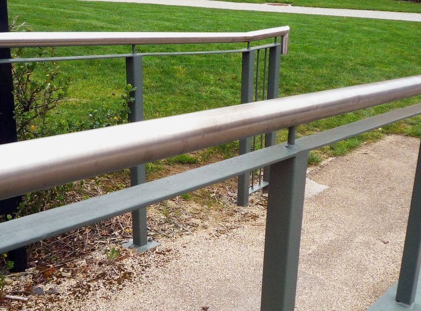
1 12 13 14 15 16 17 18 19 20 21 22 23 24 25 26 27 28 29 30
1 12 13 14 Handrails
15 16 provided
17 18 on19both
20sides
21 of 22
ramp,
23and24
following
25 26the line
27 of28
the ground
29 30
surface. Supports do not get in the way of hands and the railing turns downwards at
1 12 13 14 the
15 end
16 to avoid
17 clothes
18 19 getting
20 21snagged.
22 23 24 25 26 27 28 29 30
Photo Design Tip
1 12 13 14 15 16 17 18 19 20 21 22 23 24 25 26 27 28 29 30
R Steel handrails are cold and uncomfortable to touch for many people.
Specify timber or plastic-coated handrails to avoid this problem.
Provide a second lower handrail for people of lower stature and children.
Handrails
Design Considerations and Awareness
Handrails should be provided on both sides of a ramp or steps and should be
continuous around the landings as well.
The design of the handrail should take into consideration all users. Ensure that
brackets do not get in the way of someone who needs to grip around the entire
handrail and/or hold on all the time. Locate brackets underneath the handrail, far
enough away from the adjacent wall or surface to prevent knuckles being grazed.
Extending the handrail sufficiently beyond the line of the first and last step or edge
of a ramp makes it easier for people to approach or leave the steps or ramp. If the rail
is turned towards the wall or downwards, then someone who has visual difficulties
will know that the end of the stair has been reached. An additional handrail at a lower
height will be beneficial to people of shorter stature, including children.
People who need to grasp a handrail firmly will find a cold rail uncomfortable or even
painful. Therefore the choice of material for the handrail should be comfortable for
all, for example by using timber or plastic coated steel.
45Universal Design Guidelines For Homes in Ireland
UD Home • and UD Home X Guidance
•• Design the handrail so that it is:
• Extended 300mm beyond the end of the first and last step and
the ends of a ramp.
• Constructed with profiles which are circular in cross-section
(40-50mm diameter) or elliptical (50mm wide and 38mm deep) which
are easy to grasp.
• Supported centrally and at intervals on the underside,
so that fingers aren’t knocked.
• Constructed with a clear gap of minimum 75mm below the handrail. Set
out with a clearance from a wall of minimum 50mm with a smooth wall,
and 75mm for a rough surface.
• Installed with a positive end, curving downwards or against the wall.
• Visually contrasting with the background.
• Warm to touch - timber or plastic-coated steel are acceptable.
• Continuous across landings and ramps or steps, and easily distinguishable
from the background.
• Set the handrail at 900–1000mm above the pitch line of the stair or ramp, and
1100mm above landings.
XX Provide an additional handrail at 600–750mm height above the pitch line
of the stair or ramp for people of smaller stature or children, of diameter
25 – 32mm to suit smaller hands.
46Home Location and Approach: Section 01
Technical Sketch:
Dimensions for handrails.
A Ramp or steps.
b Supporting structure.
50–75mm
50mm
75mm
25–32mm
75mm
900–1000mm
600–750mm
b
A
47Universal Design Guidelines For Homes in Ireland
12 13 14 15 16 17 18 19 20 21 22 23 24 25 26 27 28 29 30
Access path is well-lit and lighting does not obstruct the clear width.
12 13 14 15 16 17 18 19 20 21 22 23 24 25 26 27 28 29 30
Photo Design Tip
12 13 14 15 16 17 18 19 20 21 22 23 24 25 26 27 28 29 30
R The lighting is very directional and may result in the pooling of light.
It is preferable to have an even lighting level.
12 13 14 15 16 17 18 19 20 21 22 23 24 25 26 27 28 29 30
Lighting
Design Considerations and Awareness
Lighting around the entrance to the home or the apartment building is important
for safety, security, and ease of use for everyone.
The route from the gate on the street to the entrance of the home should be easily
legible at all times, with an even, adequate spread of light across the route. Avoid
pools of light or dark, reflections or glare.
Lighting to steps and ramps should be located so that it clearly highlights the tread
and riser surfaces or the ramp slopes without casting shadows. If lights are fitted at
a low level the light source should not be visible, as this can cause glare. Also avoid
the use of floodlights because of the glare.
Lighting should be provided around an entrance door to highlight the location
and orientate people at night or when the weather is overcast. External canopies
should not block out any of the external lighting. Ensure that the door number and
keyhole are adequately illuminated.
48Home Location and Approach: Section 01
A Passive Infrared (PIR) sensor-activated light can prevent the need to locate a
switch, and if it is linked with a sounder which is audible inside the home, this will
help to advise the occupants with vision or hearing difficulties that someone is
approaching. Sensor lights need to be located and adjusted so that they are not
switched on inadvertently as this can cause anxiety among a household who may
be continually alerted by a light or sound activated by passers-by and animals.
UD Home • and UD Home X Guidance
•• Provide an external light or lights to all entrances.
• Provide at least the recommended levels of illumination (lux) externally as follows
(measured at ground level):
Entrances 100
Pedestrian access routes and walkways 50
Walkways, if colours are to be visible 30
Steps, ramps and landings 100
Designated parking spaces 30
Passenger setting-down points 50
Signage 30
• If it is important that colours are to be visible, then 50 lux min. illumination is required.
•• Ensure glare ratings are generally less than or equal to 50 lux.
• Ensure that access routes are well lit with an even spread of light.
•• Ensure that the door number and keyhole are adequately illuminated.
• Provide P.I.R. sensor-activated lighting which is adjusted to suit its location.
• Install lighting along one side of the access route only to avoid confusion.
•• Ensure that kerbs are illuminated where they are intended to be used as guides
along a route.
49Universal Design Guidelines For Homes in Ireland
13 14 15 16 17 18 19 20 21 22 23 24 25 26 27 28 29 30
Low maintenance planting defines boundaries and provides privacy and security.
13 14 15 16 17 18 19 20 21 22 23 24 25 26 27 28 29 30
13 14 15 16 Planting
17 18 19 20 21 22 23 24 25 26 27 28 29 30
Design Considerations and Awareness
13 14 15 16 17 18 19 20 21 22 23 24 25 26 27 28 29 30
Planting provides an opportunity for personalisation of a home, visual interest,
some control of privacy and views, and definition of boundaries. In apartment
developments planting may also soften hard, reverberating surfaces.
Avoid installing plants which produce high levels of pollen dispersal at approaches
to apartment buildings or houses, as these can cause distress to people who suffer
from allergies. Avoid plants with poisonous fruit or flowers that might be within
reach of children. Planting design should avoid creating a hiding place for a potential
intruder, for example within or behind a large shrub. Generally planting should
achieve a clear zone between 1 and 2 metres in height, in order to ensure all areas
are visible and therefore improve safety and security.
Distinctive trees and shrubs, scented flowers, colourful plants with berries, fruit or
flowers, or unusual leaves, will all help to distinguish one building or home from
another. This is very helpful to people who have vision or cognitive difficulties.
More information is provided about planting and gardens in Section 3.
UD Home • and UD Home X Guidance
•• Ensure that planting provided does not affect the clear width required for
any pathway, steps or ramp.
• Avoid designing a planting scheme which might provide hiding places for a
potential intruder.
• Avoid installing plants which might cause allergies or other health problems.
•• Distinguish between similarly designed homes and apartment buildings by
means of different planting schemes.
50Home Location and Approach: Section 01
4 15 16 17 18 19 20 21 22 23 24 25 26 27 28 29 30
4 15 16 17 Robust
18 19and20conveniently
21 22 located
23 24 enclosure
25 26 for27communal
28 29 bin30store with
firm, level, non-slip ground surface. Pedestrian access for home owners
4 15 16 17 is18from19the 20
side 21
pavement.
22 23 24 25 26 27 28 29 30
Photo Design Tip
4 15 16 17 18 19 20 21 22 23 24 25 26 27 28 29 30
R Please note that the dropped kerb in the image is for the movement of bins
and is not suitable for wheelchair-users. Bin stores should be accessible for
everyone to use. A level area is required in front of the gates for ease of access
by a wheel-chair user.
A bin store will need an accessible and easy to use external tap for convenient
cleaning of the area and bins.
Refuse Disposal and Recycling
Design Considerations and Awareness
The design and layout of refuse disposal for all homes should be easy to access
and use, and avoid causing a nuisance in terms of unsightly appearance, noise
or smells. Refuse arrangements will depend upon storage capacity, collection
methods and frequency of collections.
For individual houses, a storage location for bins should be provided in an
accessible location that is convenient to the house and collection point.
For apartment blocks and housing complexes, the collection point for communal
waste should be conveniently located. A refuse storage location close, but not
adjacent, to shared entrances is usually best for bagged waste carried down and
deposited by residents.
Alternatives to wheelie bin collection exist in apartment buildings, such as the
incorporation of vertical refuse chutes or the use of an underground refuse system
51Universal Design Guidelines For Homes in Ireland
with a small accessible silo at ground level. These should be carefully designed
so as to avoid noise and smells and to accommodate collection procedures.
Provide enough space inside the home to store non-recyclable and recyclable
waste in an accessible location at an accessible height. Kitchen cupboards can
be fitted with separated bins for different sorts of recyclable waste, and these are
often colour-coded for ease of distinction.
UD Home • and UD Home X Guidance
•• Ensure compliance with the local authority’s storage and collection systems.
• Provide storage space within the home for non-recyclable waste and recyclable
waste, bearing in mind the level of pre-sorting of recyclable waste required by the
local authority.
• Provide storage for food waste internally, and composting space for food and
organic waste externally in the gardens of houses and ground floor units.
• Ensure that bins and bin storage areas are easy to use and accessible, and do not
require anyone to lift a bin bag above a height of 1100mm.
• Locate the communal bin store near the entrance of the block to ensure that
people use it.
• Provide all refuse storage facilities with a hard, level non-slip floor and a tap to
facilitate cleaning.
• If refuse chutes are installed, ensure that:
• there is adequate space around refuse chutes for a 1500mm clear turning circle.
• hoppers open wide enough for bags to be inserted easily.
• hoppers are located at a height of 700-1100mm from floor level.
• chutes are coated with a sound-deadening material to avoid noise nuisance.
• there is a nearby point with a water supply for washing down and cleaning chutes
regularly.
UD Home XX Guidance:
Consider providing:
• A central accessible composting point for organic waste (grass cuttings, raw fruit
and vegetable peel) in large developments.
• An Underground Refuse System which is accessible and maintains a clean and
tidy environment.
• A bespoke pick-up system for refuse disposal offered by a caretaker or estate
officer for those who have difficulty accessing their refuse storage space.
52You can also read