High Voltage Gain Multi-port Bidirectional DC-DC Converter with an Effective Multi-loop Control Strategy for PV/Battery Integrated Systems
←
→
Page content transcription
If your browser does not render page correctly, please read the page content below
EUROPEAN
             MECHANICAL
             SCIENCE                                                                                                       Research Paper
     e-ISSN: 2587-1110

     High Voltage Gain Multi-port Bidirectional DC-DC Converter
     with an Effective Multi-loop Control Strategy for PV/Battery
                         Integrated Systems
                                         Murat Mustafa Savrun1* , Alihan Atay2
         1Adana Alparslan Türkeş Science and Technology University, Department of Electrical & Electronics Engineering, 01250, Adana, Turkey
                                         2
                                          Solvaytech Engineering Industry and Trade LTD. Co., Adana, Turkey

        Abstract
       This study proposes a novel isolated bidirectional multi-port converter (MPC) based on a switched-capacitor
       converter and a half-bridge converter with an effective control scheme for photovoltaic (PV) powered and
       battery buffered systems. The proposed power electronics converter interface integrates the converters to the
       ports which are connected with a battery coupled common DC busbar and high-frequency transformer (HFT).
       Thus, the three-port converter is formed without any need for an additional converter to regulate battery power
       flow. In addition, to transfer power from a low voltage PV energy unit to the battery and load, a single switch
       DC-DC converter with high voltage gain is proposed. The power flow between the ports is controlled by an
       effective multi-loop control scheme that is able to perform a smooth transition between the loops. In order to
       validate the viability and effectiveness of the proposed MPC, a proof-of-concept simulation model has been
       developed with a 3 kW PV and 220 V 12 Ah battery. The performance of the proposed converter has been
       analyzed for different case studies, including dynamic operating and loading conditions.
       Keywords: Multi-port DC-DC converter, switched-capacitor, photovoltaic, battery, multi-loop controller

1. INTRODUCTION                                                              The power flow between the RE- based energy unit, battery
                                                                             unit, and load is performed using power electronics conver-
1.1. Overview
                                                                             ter interfaces. Traditionally, individual converters are emp-
In the last few decades, the use and depletion of fossil fuels               loyed and controlled in a decentralized manner to regulate
have accelerated in parallel with the significant increase in                the power flow [10]. Because of that, traditional RES-powe-
electricity demand [1]. The environmental concern and dep-                   red systems have high computational loads and costs. To
letion of fossil fuels have led to develop renewable energy                  overcome the aforementioned limitations, multi-port con-
sources (RESs) powered clean applications such as electric                   verters (MPC) are used, wherein RES-based energy units,
vehicles [2], microgrids [3], residential grid-tie inverters [4].            battery units, and loads are connected to different ports of
Besides, RESs generating power in DC form are able to in-                    the MPC.
tegrate with DC loads used in DC microgrids, which have
become widespread in recent years, without using additio-                    1.2. Literature Survey
nal inverter devices [5]. Although RESs are good candidates                  MPCs are emerging power electronics solutions in order to
for the aforementioned applications because of such advan-                   integrate multi-inputs/outputs with combined functiona-
tages, they are by nature unstable in their availability and                 lities and control schemes. MPCs can be divided into two
capacity [6]. The instantaneous production values of RESs                    categories as isolated and non-isolated converters and are
vary with natural conditions such as solar irradiation/tem-                  presented in [11-13]. Non-isolated topologies have advan-
perature [7], hydrogen pressure/temperature [8], and wind                    tages such as simpler structure and compactness by the lack
speed [9]. RES-based energy systems are frequently equ-                      of a high-frequency transformer whereas they are not able
ipped with energy storage units in order to eliminate the                    to provide isolation and flexible voltage range [14]. On the
non-linear behavior drawback of RESs. Battery units make                     other hand, isolated MPCs provide flexible voltage ranges
it possible to provide uninterrupted power to loads by buffe-                via HFT turns ratio as well as isolation between the ports.
ring fluctuations and interruptions of RESs.

                                                              European Mechanical Science (2021), 5(3): 99-104
* Corresponding author                                        doi: https://doi.org/10.26701/ems.934248
  Email: msavrun@atu.edu.tr                                   Received: May 7, 2021
                                                              Accepted: June 1, 2021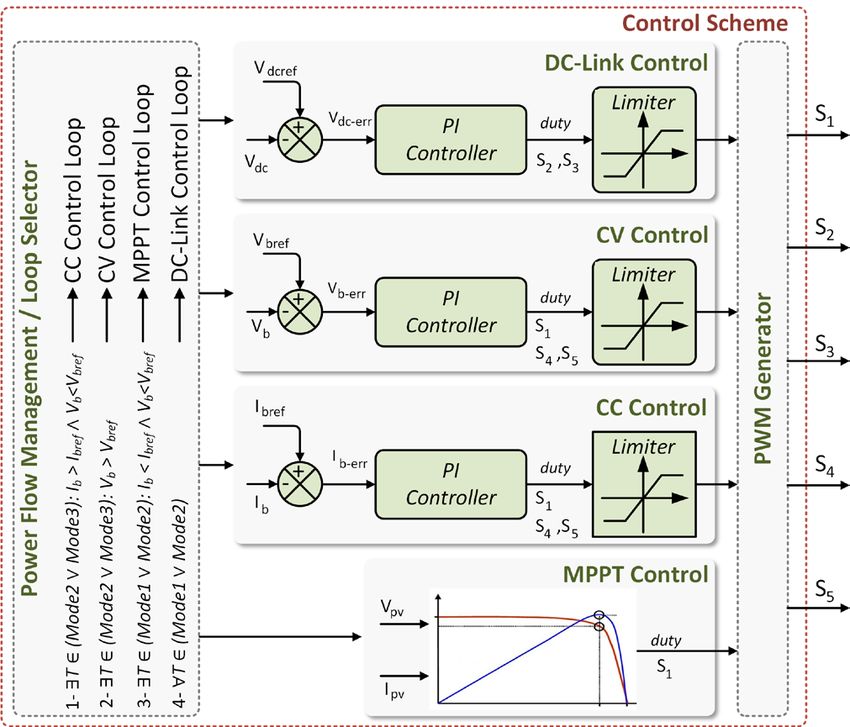
High Voltage Gain Multi-port Bidirectional DC-DC Converter with an Effective Multi-loop Control Strategy for PV/Battery Integrated Systems

Isolated MPCs are good candidates for RES powered and                        related topology.
battery buffered systems because of their flexibility in per-
forming power flow between the different ports.                              1.3. Key Contributions
                                                                             Literature review reveals the current researches focused on
Several isolated MPC topologies have been presented in
                                                                             MPCs in order to integrate multi-input/output ports with
the literature to integrate multi-input/output ports. Many
                                                                             reduced switches and complexity. In addition, it is conc-
studies have addressed isolated MPCs using the derivations
                                                                             luded that the unidirectional DC-DC converters that have
of bridge converters that have capabilities of bidirectional
                                                                             a high voltage conversion ratio to extract maximum power
power flow, galvanic isolation, zero-voltage switching, and
                                                                             from RESs play a critical role for RES-powered systems.
zero-current switching [15]. Among the derivations of brid-
                                                                             Among the related DC-DC converter topologies, switc-
ge converters, full-bridge converters have advantages of two
                                                                             hed-capacitor boost converter and half-bridge converter
times higher output voltage and higher power transfer capa-
                                                                             excel with the aforementioned advantages.
bility, while half-bridge topologies with fewer switching de-
vices are advantageous in relatively low power applications                  This paper proposes a new MPC that is equipped with swit-
[16]. The turns ratio of HFTs makes it possible to provide                   ched-capacitor DC-DC converter in order to integrate RES
flexibility in voltage conversion ratio, while the high turns                with an isolated DC-DC converter via a battery coupled
ratio raises the problem of low efficiency. Therefore, MPCs                  common busbar. Since an additional DC-DC converter that
that are endowed with low turns ratio HFTs and integrated                    regulates the power flow of the battery contributes signifi-
with high gain converters stand out as in [7]. The power flow                cantly to the size and cost of the overall system, the power
path at the MPC port where RESs are connected is designed                    flow of the battery is regulated by the existing converters
to be unidirectional due to the nature of RESs. Because of                   considering operation conditions. The proposed system is
that, RESs are equipped with unidirectional DC-DC con-                       equipped with a multi-loop control structure that operates
verters. Various unidirectional high gain DC-DC converter                    adaptively and allows instantaneous switching between the
topologies developed and applied in literature are reviewed                  loops. In order to validate the viability and effectiveness of
in [17]. Step-up DC-DC converters temporarily store low                      the proposed system, different load and temperature scena-
voltage input energy on magnetic field storage components                    rios are operated.
and transfer it to the output in high voltage levels [17]. The               The pattern of this study is organized as follows: the power
fundamental step-up converter is the traditional boost con-                  circuit configuration of the proposed system is given in Se-
verters which have a restricted voltage gain with high out-                  ction 2. In Section 3, the operation modes of the proposed
put voltage ripple. In order to eliminate the output voltage                 MPC and overall control scheme are explained in detail.
ripples, interleaved topologies have been proposed [18].                     Performance analysis and case studies are investigated and
Furthermore, multi-leg/multi-phase interleaved [19, 20], ca-                 discussed in Section 4. Finally, conclusions are presented in
pacitor clamped h-bridge [21], and tristate boost converter                  Section 5.
[22] topologies are employed in order to further decrease
the output voltage ripple and to improve the voltage con-                    2. POWER CIRCUIT CONFIGURATION OF THE
version ratio. However, the related topologies have a limited                PROPOSED CONVERTER
gain and many active switching devices. The coupled induc-
                                                                             The power circuit configuration of the proposed MPC which
tor topologies make it possible to provide high voltage gain,
                                                                             is illustrated in Figure 1 consists of a half-bridge converter, a
but relatively large current ripples decay the service life of
                                                                             controlled full-wave rectifier, a switched-capacitor DC-DC
the connected port RES or battery unit [21]. Tang et al. [23]
                                                                             converter, and a secondary center-tapped high-frequency
proposed a hybrid switched inductor converter. The swit-
                                                                             transformer (HFT). The proposed converter interface is
ched inductor topology has a high voltage gain. However,
                                                                             purposed to integrate battery, PV, and load and supervise
the voltage stress on the diodes is the main drawback of the
                                                                             the optimal power flow between input and output ports.

                                                    Figure 1. Circuit design of the proposed MPC

100 European Mechanical Science (2021), 5(3): 99-104
    doi: https://doi.org/10.26701/ems.934248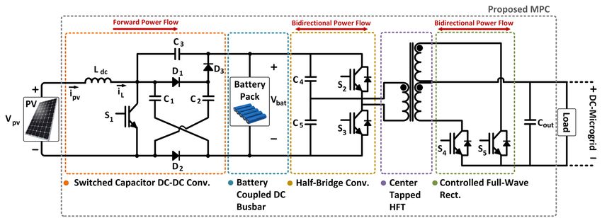
Murat Mustafa Savrun; Alihan Atay

The switched-capacitor DC-DC converter is used to trans-
fer power from PV to the battery/load with high efficiency.
Besides, the related DC-DC converter makes it possible to
connect low voltage PV into a relatively high voltage battery
due to its high voltage conversion ratio capability. Half-bri-
dge converter allows bidirectional power flow by transfer-
ring power from input ports to the output port and from the
output port to the battery. While the half-bridge converter
operates as an inverter during forward power flow, it ope-
rates as an uncontrolled full-wave rectifier during reverse
power flow. The galvanic isolation between the input and
output ports is provided by HFT with low turns ratio. The
controlled full wave rectifier located on the secondary side,
on the contrary to the half-bridge converter, operates as an
uncontrolled full-wave rectifier during the forward power
flow and operates as an inverter during reverse power flow.
                                                                               Figure 2. Control scheme of the proposed MPC
The proposed MPC integrates three different converters; (i)
the switched-capacitor DC-DC converter, (ii) the half-bri-        the load via PV and battery. In this mode, the battery ope-
dge converter, and (iii) the controlled full-wave rectifier       rates in discharging mode. In mode 2, PV feeds the load,
via battery coupled common DC busbar and HFT. On the              whereas the battery is charged via PV. Mode 3 represents the
primary side, while the battery operates as a common DC           reverse power flow that is towards from the load side to the
bus, the switched-capacitor DC-DC converter performs the          battery. In this mode, the battery operates in charging mode.
maximum power point tracking, constant current (CC), and          In mode 1, the power of the load is provided from the PV
constant voltage (CV) charging methods. The DC-busbar             and battery at the same time. There are two potential cir-
of the half-bridge converter is fed by PV and buffered by         cumstances in this case. The primary condition may take
battery. Thus, uninterrupted power transfer to the load is        place when the load power consumption is higher than the
provided. The relationship between the PV and battery vol-        available PV power. In this time interval, the battery buf-
tages is computed using the duty cycle of S1. It is expressed     fers the PV to transfer uninterrupted power to the load. The
as follows [24, 25];                                              secondary condition is that the PV operates under rated
  Gain
   =
         Vbat
          =
                2                                                 power due to environmental situations such as irradiation
         V pv 1 − D                                               (i.e. the generated power of PV decreases with irradiation
                                                            (1)
                                                                  reduction). The analytical relationship between power flows
where Vbat and Vpv represent the battery voltage and PV
                                                                  is given in Eq (2).
output voltage, respectively. D describes the duty cycle of
                                                                     t1               t1                   t1
switch S1 and varies between 0-1 considering operation con-          P ( t ) dt ∫
                                                                    ∫=                     Ppv ( t ) dt + ∫ Pbat ( t ) dt     (2)
                                                                     t0 load          t0                   t0
ditions of the system.
                                                                  In mode 2, the PV supplies battery, and the load, namely
3. CONTROL SCHEME OF THE PROPOSED CONVERTER                       the power produced by PV feeds the load and charges the
The detailed control structure is shown in Figure 2. The main     battery at the same time. This situation may occur under low
aims of the overall controller scheme are: (i) to ensure the      load consumption ratings. The PV power could be decre-
continuity of the power transfer to the load with constant        ased when the low power is consumed. However, in cases
DC-link voltage, (ii) to transfer excessive power produced        where the PV generation is insufficient to supply the load,
by PV to the battery, (iii) to provide bidirectional power flow   the battery must be charged to keep the DC-link voltage
between the ports. The effective control structure for the        constant by buffering the PV. In cases where the battery sta-
proposed MPC is a multi-loop control structure that is com-       te of charge is less than 100%, the excessive power of the
posed of power flow management, MPPT, CC/CV charging,             PV is used to charge the battery. During this time interval,
and DC-link control. The system operates adaptively and           power flows are expressed mathematically in Eq (3).
allows instantaneous switching between the control loops.            t2               t2                   t2
                                                                     P ( t ) dt ∫
                                                                    ∫=                     Ppv ( t ) dt − ∫ Pbat ( t ) dt     (3)
                                                                     t1 load          t1                   t1
The optimal power flow between input energy units and the
output load with respect to the instantaneous PV generati-        In mode 3, the battery is charged from the load side. This
on, charge characteristics of the battery, and load variations    case may occur under a condition where there is no solar ir-
are the main part of the proposed converter operation. Ac-        radiation and the battery is charged by the DC-microgrid to
cording to the instantaneous states of the ports, there are       which the load is connected. By this way, the power flowing
three possible power flow circumstances as mode1, mode 2,         through the PV is zero. The power flow for this state is exp-
and mode 3. Mode 1 corresponds to power transfer towards          ressed as below:

                                                                               European Mechanical Science (2021), 5(3): 99-104 101
                                                                                       doi: https://doi.org/10.26701/ems.934248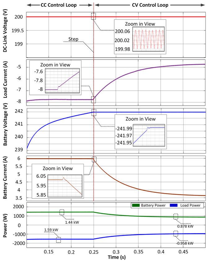
High Voltage Gain Multi-port Bidirectional DC-DC Converter with an Effective Multi-loop Control Strategy for PV/Battery Integrated Systems

        t3                 t3                   t3                                     rol loops are enabled. If the battery charge current reaches
    ∫        P
        t2 load
                  ( t ) dt ∫=P ( t ) dt & ∫ Ppv ( t ) dt
                            t bat
                            2              t    2
                                                              0               (4)      the charge current limit, the MPPT control loop switches to
                                                                                       the CC control loop. The CC control loop rises the battery
  The power transfer towards the load is performed using the
                                                                                       voltage to its reference value of 242 V. The CV control is
  DC-link control loop continuously, while the latter control
                                                                                       enabled following the completion of the described opera-
  loops are enabled considering the instantaneous power pro-
                                                                                       tion of the CC loop. The CV charging continuous until the
  duction value of PV. The power transfer from the load side to
                                                                                       charging current gradually decreases to 0.05C. The CC/CV
  the battery is performed using CC/CV charging algorithms.
                                                                                       charging is achieved by adjusting the duty cycle of the switch
  The common aspect of the aforementioned control loops is
                                                                                       S1. In addition, the CC/CV control loops are also enabled in
  the use of the pulse width modulation (PWM) method. The
                                                                                       mode 3, which is another power transfer state towards to
  duty cycle values of the switches regulate the power flow ra-
                                                                                       battery. The duty cycle value of the S1 switch is computed
  ting by adjusting the voltages of output DC-link and battery
                                                                                       using PI controllers during related control loops are enabled.
  coupled DC busbar.
                                                                                       The CC control loop computes the duty cycle by using the
  The DC-link control loop is used to regulate the output                              error value between the reference (Ibref) and actual (Ib) values
  DC-link voltage by triggering S2 and S3 switching devices.                           of the battery current while the CV control loop computes
  The duty cycles of switches S2 and S3 with a 180o phase shift                        the duty cycle by using the error value between the reference
  between each other varies within the limits of 0-50 %. A duty                        (Vbref) and actual (Vb) values of the battery voltage.
  cycle of more than 50% causes the relevant switches to open
  simultaneously and short circuit. The duty cycles of the                             4. PERFORMANCE ANALYSIS
  switches are computed using a PI controller. The difference                          In this section, to verify the effectiveness and viability of the
  between the reference (Vdcref) and actual voltages (Vdc) of the                      proposed MPC and the controller, a 3 kW proof-of-concept
  output load is applied to the PI controller.                                         model which consists of 3 kW PV and 220 V 12 Ah battery
  The MPPT control loop is activated during mode 1 and                                 has been developed using MATLAB/Simulink. The parame-
  some states of mode 2. The MPPT control loop is used to                              ters of the simulation model are shown in Table 1. The per-
  extract maximum power from PV by triggering the S1 swit-                             formance of the proposed system is tested under two case
  ching device. The maximum power tracking is performed                                studies including all modes of operations. The case studies
  by the perturb and observe (P&O) MPPT method due to                                  which are summarized in Table 2 are formed by varying the
  the ease of operation and reduced computational load. The                            irradiation of PV and loading.
  controller monitors the output voltage (Vpv) and current (Ipv)                                          Table 1. Parameters of the proposed MPC
  of PV and computes the instantaneous available power. The                                 System         Parameters                                   Value
  algorithm perturbs the operating voltage to ensure maxi-                                                 PV maximum power (1000W/m2)                3197 W
  mum power by adjusting the duty cycle of switch S1. The                                                  Maximum Power Point Voltage (1000W/m2)       87 V
  operating voltage perturbation is performed by computing                                                 Maximum Power Point Current (1000W/m2)     36.75 A
                                                                                              PV
                                                                                                           PV maximum power (250W/m2)                 801.3 W
  the instantaneous duty cycle of S1 switch as follows;
                                                                                                           Maximum Power Point Voltage (250W/m2)       86.9 V
    D=   Dold + ∆D         (if P > Pold )
     new                                                                      (5)                          Maximum Power Point Current (250W/m2)       9.221A
                                                                                                           Battery Capacity                            12 Ah
    D=   Dold − ∆D         (if P < Pold )
     new                                                                      (6)           Battery        Battery Nominal Voltage                     220 V
=Dnew D=   (if P Pold )                                                                                    Battery Maximum Charge Current                6A
       old                                                                    (7)
                                                                                                           Inductor (Ldc)                               1 mH
  The available excessive power of PV is crucial in enabling                               Switched        Capacitor (C1)                              250 uF
  one of the MPPT or CC control loops. The battery char-                                   Capacitor       Capacitor (C2)                              250 uF
  ging scenario has great importance to improve the service                                                Capacitor (C3)                              500 uF
  life of the battery. Therefore, the battery charge current is                                            Half Bridge Capacitors (C4, C5)              2 mF
  frequently is restricted with 0.5 C (C represents the nomi-                                              DC-Link Capacitor (Cout)                     1 mF
                                                                                            General        Nominal DC-Link Voltage                       200
  nal capacity of the battery) charging current. Considering
                                                                                                           Switching Frequency                         20 kHz
  the charging current limits of the battery, the related cont-
                                                                                                           HFT Turns Ratio                              1:2:2
                                                                     Table 2. Details of case studies
                                                                      Case 1                                               Case 2
                                                                  Time Intervals                                       Time Intervals
                             Time                0-0.25 s           0.25-0.5 s       0.5-0.75 s           0.75-1 s      0-0.25 s         0.25-0.5 s
                          Irradiation           300 W/m2           650 W/m2         1000 W/m2           1000 W/m2          -                 -
                            Celcius               25 Co               25 Co            25 Co               25 Co           -                 -
                       DC-Link Demand            1500 W              1500 W           1500 W              1500 W       -2000 W           -2000 W
                   Battery Charge/Discharge     Discharge            Charge         Charge (CC)         Charge (CV)   Charge (CC)       Charge (CV)
                             Mode                Mode 1              Mode 2           Mode 2              Mode 2        Mode 3            Mode 3

 102 European Mechanical Science (2021), 5(3): 99-104
     doi: https://doi.org/10.26701/ems.934248
Murat Mustafa Savrun; Alihan Atay
raise in irradiation, while the battery is first discharged and
then charged to the maximum voltage value.
The second case represents mode 3 operation in which the
battery is charged by the DC microgrid. Figure 4 shows the
steady-state and dynamic responses of the proposed con-
verter during reverse power flow conditions. In this case
study, the battery is charged with a constant current during
the time interval of 0-0.5 s. The charge current of the bat-
tery is adjusted by the CC control loop. The CC charging is
followed by CV charging during the time interval of 0.5-1 s.
The performance waveforms highlight that the proposed
MPC and controller smoothly regulates the steady-state and
transient power-sharing during different irradiation and loa-
ding variations. Besides, the efficiency of the proposed con-
verter has been also evaluated. As can be seen from Figure
3-4, the efficiency values considering the operating modes
are 96%, 96.8%, and 90%, respectively. The efficiency values
of the proposed converter show its effectiveness under all
possible power flow conditions.
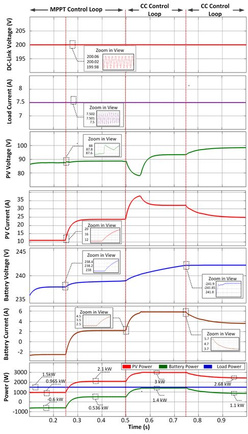
Figure 3. Performance results for case 1
The first case includes operating conditions in which mode
1, mode 2, and all control loops (MPPT, CC, CV, DC-link)
are active, as well as the state responses of the transitions
between these modes and loops. The different time inter-
vals correspond to different operation modes and active
control loops. Figure 3 shows the steady-state and dynamic
responses of the proposed system during loop and mode
transitions. It can be seen from the results that when the
instantaneous power value of PV is lower than the load de-
mand, the battery buffers and provides uninterrupted power
to load. Following the raise in irradiation, the battery switc- Figure 4. Performance results for case 2
hes to charging in parallel with the increase in instantaneous
power value of PV. During the state that the PV has relati-
5. CONCLUSION AND DISCUSSION
vely low output power, the MPPT control loop regulates the This study proposes a novel isolated bidirectional multi-port
power flow from PV and the battery is charged with exces- converter (MPC) based on a switched-capacitor converter
sive power. However, in the case of high power generation and a half-bridge converter with an effective control sche-
from PV, the CC control loop is activated and the battery me. The main advantages of the proposed converter are as
current is restricted. Following the battery voltage reaches follows: (i) low voltage PV integration with high voltage gain
a certain value, the CV control loop begins and keeps the and high-efficiency switched-capacitor DC-DC converter,
output voltage of PV at a certain value. It is seen that the (ii) battery integration without an additional converter, (iii)
power of PV is increased to 1 kW, 2 kW, and 3 kW with the reduced switch topology, (iv) cost-effectiveness (v) bidirec-
tional power flow capability. The effectiveness of the propo-
European Mechanical Science (2021), 5(3): 99-104 103
doi: https://doi.org/10.26701/ems.934248High Voltage Gain Multi-port Bidirectional DC-DC Converter with an Effective Multi-loop Control Strategy for PV/Battery Integrated Systems
sed MPC is evaluated under various operating conditions. ti-input DC/DC converters in connection with distributed genera-
The results show that the proposed MPC performs all the tion units – A review. Renewable and Sustainable Energy Reviews,
aforementioned functionalities. In addition to its satisfac- 66: 360-379. doi: 10.1016/j.rser.2016.07.023.
tory performance under steady-state conditions, it provides [14] Chaudhury T., Kastha, D. (2020). A High Gain Multiport DC–DC
effective power transfer with smooth transitions between Converter for Integrating Energy Storage Devices to DC Microgrid.
IEEE Transactions on Power Electronics, 35:10501-10514. doi:
control loops during transient conditions.
10.1109/TPEL.2020.2977909.
REFERENCES [15] Savrun, M. M., Köroğlu, T., Tan, A., Cuma, M. U., Bayindir, K. Ç.,
[1] Das, M., Agarwal, V. (2016). Design and Analysis of a High-Effi- Tümay, M. (2020). Isolated H-bridge DC–DC converter integrated
ciency DC–DC Converter With Soft Switching Capability for Re- transformerless DVR for power quality improvement. IET Power
newable Energy Applications Requiring High Voltage Gain. IEEE Electronics, 13: 920-926. doi: 10.1049/iet-pel.2019.0687
Transactions on Industrial Electronics, 63: 2936-2944. doi:10.1109/ [16] Chakraborty S., Chattopadhyay, S. (2017). Minimum-RMS-Current
TIE.2016.2515565. Operation of Asymmetric Dual Active Half-Bridge Converters With
[2] Shen, D., Lim, C.-C., Shi, P. (2020). Robust fuzzy model predicti- and Without ZVS. IEEE Transactions on Power Electronics, 32: 5132-
ve control for energy management systems in fuel cell vehicles. 5145. doi: 10.1109/TPEL.2016.2613874.
Control Engineering Practice, 98: 1-12. doi: 10.1016/j.conengp- [17] Forouzesh, M., Siwakoti, Y. P., Gorji, S. A., Blaabjerg, F., Lehman, B.
rac.2020.104364. (2017). Step-Up DC–DC Converters: A Comprehensive Review of
[3] Naidu, B. R., Panda, G., Siano, P., (2018). A Self-Reliant DC Microgrid: Voltage-Boosting Techniques, Topologies, and Applications. IEEE
Sizing, Control, Adaptive Dynamic Power Management, and Expe- Transactions on Power Electronics, 32: 9143-9178. doi: 10.1109/
rimental Analysis. IEEE Transactions on Industrial Informatics, 14: TPEL.2017.2652318.
3300-3313. doi: 10.1109/TII.2017.2780193. [18] Wu, H., Zhang, J., Qin, X., Mu, T., Xing, Y. (2016). Secondary-Side-Re-
[4] Gangatharan, S., Rengasamy, M., Elavarasan, R. M., Das, N., Hossa- gulated Soft-Switching Full-Bridge Three-Port Converter Based on
in, E., Sundaram, V. M. (2020). A Novel Battery Supported Energy Bridgeless Boost Rectifier and Bidirectional Converter for Multiple
Management System for the Effective Handling of Feeble Power in Energy Interface. IEEE Transactions on Power Electronics, 31: 4847-
Hybrid Microgrid Environment. IEEE Access, 8: 217391-217415. doi: 4860. doi: 10.1109/TPEL.2015.2473002.
10.1109/ACCESS.2020.3039403. [19] Saadi, R., Hammoudi, M. Y., Kraa, O., Ayad, M. Y., Bahri, M. (2020).
[5] Prabhakaran P., Agarwal, V. (2020). Novel Four-Port DC–DC Con- A robust control of a 4-leg floating interleaved boost converter for
verter for Interfacing Solar PV–Fuel Cell Hybrid Sources With fuel cell electric vehicle application. Mathematics and Computers
Low-Voltage Bipolar DC Microgrids. IEEE Journal of Emerging and in Simulation, 167: 32-47. doi: 10.1016/j.matcom.2019.09.014.
Selected Topics in Power Electronics, 8: 1330-1340. doi: 10.1109/ [20] Thounthong P., Davat, B. (2010). Study of a multiphase interlea-
JESTPE.2018.2885613. ved step-up converter for fuel cell high power applications. Energy
[6] Jiang, J., Gao, L., Jin, J., Luan, T. H., Yu, S., Xiang, Y. (2019). Sustainability Conversion and Management, 51: 826-832. doi: 10.1016/j.encon-
Analysis for Fog Nodes With Renewable Energy Supplies. IEEE Inter- man.2009.11.018.
net of Things Journal, 6: 6725-6735. doi: 10.1109/JIOT.2019.2910875. [21] Bi, H., Wang, P., Che, Y. (2019). A Capacitor Clamped H-Type Boost
[7] Savrun M. M., Atay, A. (2020). Multiport bidirectional DC–DC con- DC-DC Converter With Wide Voltage-Gain Range for Fuel Cell Ve-
verter for PV powered electric vehicle equipped with battery and hicles. IEEE Transactions on Vehicular Technology, 68: 276-290. doi:
supercapacitor. IET Power Electronics, 13:3931-3939. doi: 10.1049/ 10.1109/TVT.2018.2884890.
iet-pel.2020.0759. [22] Kapat, S., Patra, A., Banerjee, S. (2009). A Current-Controlled Tristate
[8] Savrun M. M., İnci, M. (2021). Adaptive neuro-fuzzy inference sys- Boost Converter With Improved Performance Through RHP Zero
tem combined with genetic algorithm to improve power extracti- Elimination. IEEE Transactions on Power Electronics, 24: 776-786.
on capability in fuel cell applications. Journal of Cleaner Production, doi: 10.1109/TPEL.2008.2008994.
299:1-11. doi: 10.1016/j.jclepro.2021.126944. [23] Tang, Y., Fu, D., Wang, T., Xu, Z. (2015). Hybrid Switched-Inductor
[9] Sefa, I., Altin, N., Ozdemir, S., Kaplan, O. (2015). Fuzzy PI controlled Converters for High Step-Up Conversion. IEEE Transactions on In-
inverter for grid interactive renewable energy systems. IET Renewab- dustrial Electronics, 62: 1480-1490. doi: 10.1109/TIE.2014.2364797.
le Power Generation, 9: 729-738. doi: 10.1049/iet-rpg.2014.0404. [24] Ismail, E. H., Al-Saffar, M. A., Sabzali, A. J. (2008). High Conversion
[10] Vettuparambil, A., Chatterjee, K., Fernandes, B. G. (2021). A Multi- Ratio DC–DC Converters With Reduced Switch Stress. IEEE Transa-
port Converter Interfacing Solar Photovoltaic Modules and Energy ctions on Circuits and Systems I: Regular Papers, 55: 2139-2151. doi:
Storage With DC Microgrid. IEEE Transactions on Industrial Electro- 10.1109/TCSI.2008.918195.
nics, 68: 3113-3123. doi: 10.1109/TIE.2020.2978709. [25] İnci, M., Büyük, M., Savrun, M. M., Demir, M. H. (2021). Design and
[11] Zhang, N., Sutanto, D., Muttaqi, K. M. (2016). A review of topologies analysis of fuel cell vehicle-to-grid (FCV2G) system with high vol-
of three-port DC–DC converters for the integration of renewable tage conversion interface for sustainable energy production. Sus-
energy and energy storage system. Renewable and Sustainable Ener- tainable Cities and Society, 67: 1-12. doi: 10.1016/j.scs.2021.102753.
gy Reviews, 56: 388-401. doi: 10.1016/j.rser.2015.11.079.
[12] Bhattacharjee, A. K., Kutkut, N., Batarseh, I. (2019). Review of Mul-
tiport Converters for Solar and Energy Storage Integration. IEEE
Transactions on Power Electronics, 34: 1431-1445. doi: 10.1109/
TPEL.2018.2830788.
[13] Khosrogorji, S., Ahmadian, M., Torkaman, H., Soori, S. (2016). Mul-
104 European Mechanical Science (2021), 5(3): 99-104
doi: https://doi.org/10.26701/ems.934248You can also read


