Finite Element Modeling of Magnitude and Location of Brain Micromotion Induced Strain for Intracortical Implants
←
→
Page content transcription
If your browser does not render page correctly, please read the page content below
ORIGINAL RESEARCH
                                                                                                                                         published: 06 January 2022
                                                                                                                                    doi: 10.3389/fnins.2021.727715

                                            Finite Element Modeling of
                                            Magnitude and Location of Brain
                                            Micromotion Induced Strain for
                                            Intracortical Implants
                                            Ali Al Abed 1 , Jason Amatoury 2 and Massoud Khraiche 3*
                                            1
                                             Department of Mechanical Engineering, American University of Beirut, Beirut, Lebanon, 2 Sleep and Upper Airway Research
                                            Group, Biomedical Engineering Program, American University of Beirut, Beirut, Lebanon, 3 Neural Engineering
                                            and Nanobiosensors Group, Biomedical Engineering Program, American University of Beirut, Beirut, Lebanon
                          Edited by:
                  Ulrich G. Hofmann,
   University Medical Center Freiburg,      Micromotion-induced stress remains one of the main determinants of life of intracortical
                             Germany        implants. This is due to high stress leading to tissue injury, which in turn leads to an
                        Reviewed by:        immune response coupled with a significant reduction in the nearby neural population
                           Walter Voit,
     The University of Texas at Dallas,
                                            and subsequent isolation of the implant. In this work, we develop a finite element model
                         United States      of the intracortical probe-tissue interface to study the effect of implant micromotion,
                        Simon Giszter,      implant thickness, and material properties on the strain levels induced in brain tissue.
      Drexel University, United States
                          Ankit Parikh,     Our results showed that for stiff implants, the strain magnitude is dependent on the
     The University of Texas at Dallas,     magnitude of the motion, where a micromotion increase from 1 to 10 µm induced an
       United States, in collaboration
                     with reviewer WV
                                            increase in the strain by an order of magnitude. For higher displacement over 10 µm, the
                  *Correspondence:
                                            change in the strain was relatively smaller. We also showed that displacement magnitude
                   Massoud Khraiche         has no impact on the location of maximum strain and addressed the conflicting results
                mkhraiche@aub.edu.lb        in the literature. Further, we explored the effect of different probe materials [i.e., silicon,
                   Specialty section:
                                            polyimide (PI), and polyvinyl acetate nanocomposite (PVAc-NC)] on the magnitude,
         This article was submitted to      location, and distribution of strain. Finally, we showed that strain distribution across
                    Neural Technology,
                                            cortical implants was in line with published results on the size of the typical glial
               a section of the journal
            Frontiers in Neuroscience       response to the neural probe, further reaffirming that strain can be a precursor to the
            Received: 19 June 2021          glial response.
         Accepted: 08 October 2021
                                            Keywords: intracortical, micromotion, FEM, implants, brain, neuron, strain, glia
         Published: 06 January 2022
                                Citation:
           Al Abed A, Amatoury J and
    Khraiche M (2022) Finite Element
                                            INTRODUCTION
 Modeling of Magnitude and Location
 of Brain Micromotion Induced Strain
                                            High-fidelity from intracortical microelectrodes recordings are central for the efforts to understand
              for Intracortical Implants.   the complexity of neural networks in awake patients or repair/bridge damaged pathways through
          Front. Neurosci. 15:727715.       open or potentially closed-loop prosthetic intervention (Chou et al., 2015; Lindner et al., 2019).
     doi: 10.3389/fnins.2021.727715         The Michigan silicon-based microelectrode, developed at the University of Michigan by Kensall

Frontiers in Neuroscience | www.frontiersin.org                                   1                                       January 2022 | Volume 15 | Article 727715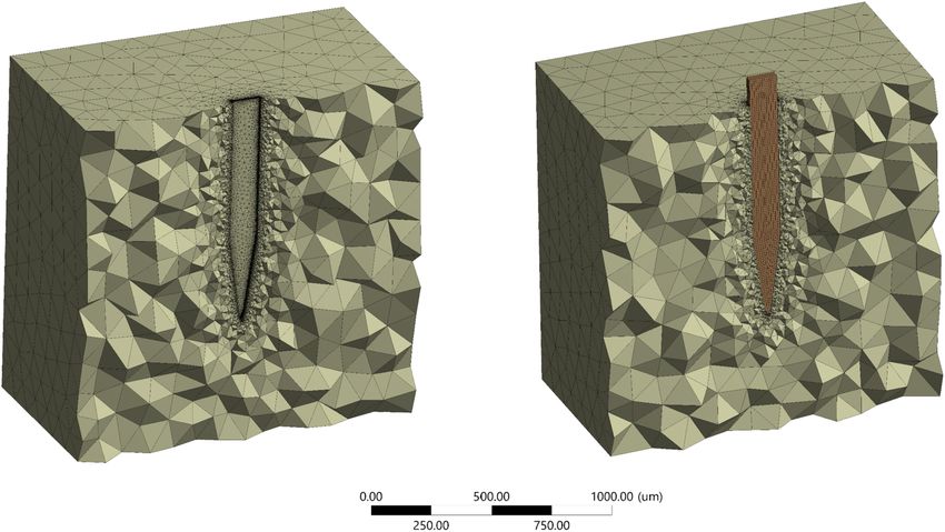
Al Abed et al. Intracortical Implants FEM Simulation
Wise and his colleagues, was the first cellular level intracortical we investigate two different probe thicknesses of a compliant
microelectrode (McAlpine, 2016). Currently, the technology is implant on the maximum strain.
used clinically in deep brain stimulation, auditory brainstem
neuroprostheses, cortical stimulation, and brain-machine
interface (Paralikar, 2009; Khraiche et al., 2013a; Kook et al., MATERIALS AND METHODS
2016). Despite these applications, chronic brain implants suffer
many challenges including signal loss, reduced signal-to-noise We modeled an intracortical microelectrode placed in the brain.
ratio, and unstable recordings over time (Kook et al., 2016). The displacement of the brain due to respiration ranges between 2
The implant/neural tissue interaction gives rise to a complex and 25 µm and smaller displacements due to vascular pulsations
system from a biomechanical, chemical, and bioelectrical in the brain can range between 1 and 4 µm (Muthuswamy et al.,
standpoint. One of the factors that can potentially contribute 2005). Accordingly, in this study, three values of micromotion
to limiting implant life for clinical applications of intracortical displacements (i.e., 1, 10, and 20 µm) were simulated on the
electrodes is the foreign body response at the implant-injury site stiff silicon-based Michigan probe. The model was extended to
(Campbell and Wu, 2018). This is characterized by a cascade of compare the strain values among four different probe materials:
inflammatory events, which culminate in chronic inflammation, silicon, PVAc-NC, polyimide, and hypothetical probes for 1 µm
resulting in the failure of the implant over extended periods. At displacement. In addition, a PVAc-NC probe with a thickness
the center of this response is the brain immune response driven reduced to 25 µm, equal to the silicon probe thickness, was also
by native immune cells (glia). These cells act to encapsulate the considered under 1 µm displacement. A summary of the cases
electrode, electrically isolating it from the target tissue (Figure 1). considered are presented in Table 1. From herein, silicon-based
The catalyst for the brain’s immune response includes initial implants will be referred to as stiff probes while a PVAc-NC
injury during implantation, foreign body response to implant implant will be referred to as a compliant probe.
material and shape, and chronic micromotions of the implant.
The latter is caused by breathing, heartbeats, and vascular Geometry Modeling
pulsation, or external body motion such as rapid head movement The geometry of the model consists of two parts: the brain
(Muthuswamy et al., 2003). In addition to immune response, tissue modeled as a 3D rectangular shape and a Michigan-
recent evidence points to a direct role of mechanical forces in type electrode, based on the typical design used for silicon
neural modulation, including heightened functional state and a microelectrode arrays (Subbaroyan et al., 2005), of two different
high neural firing rate (Marin and Fernandez, 2010; Khraiche thicknesses. The probe geometry with a thickness of 25 µm
et al., 2017; Fomenko et al., 2018). (Figure 2) was used to represent the stiff, Polyimide and
The above challenges have driven research efforts toward hypothetical probes, while the probe geometry with a thickness
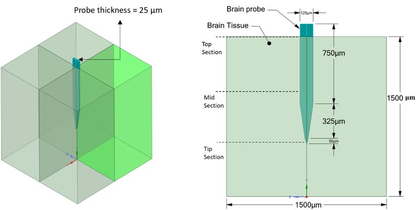
a close evaluation of the biomechanics of intracortical of 63 µm (Figure 3) was used to represent the compliant probe
microelectrode implants with a focus on the strain-induced since, as reported in Nguyen et al. (2014), the manufacturing
on neural tissue at the injury site. However, these strains process limits the thickness of compliant probes to less than
are very difficult to measure given their location deep in the 63 µm. For the brain tissue, the width and length were taken
brain. Accordingly, finite element models have been developed as 1,500 × 1,500 µm, which are much larger than the effective
to measure induced strain fields resulting from a material recording distance from the probe surface and the kill zone
mismatch between the brain tissue and the implanted probe of a single microelectrode of 140 and 60 µm, respectively
(Lee et al., 2005; Subbaroyan et al., 2005; Zhu et al., 2011; (Subbaroyan et al., 2005).
Nguyen et al., 2014; Zhang et al., 2016; Mahajan et al., 2020).
Past models have studied various parameters of the probe Material Properties
and its relationship with the strain levels and distribution. The brain tissue was approximated as a linear elastic and
However, contradicting conclusions regarding the location isotropic material, as described in Subbaroyan et al. (2005),
of the maximum strain for various materials and range of Nguyen et al. (2014), and Mahajan et al. (2020). That is because
micromotions are present (REFS). In this work, we focus on the implants were assumed to be placed in the brain tissue
investigating the impact of the range of micromotion of the brain of the cerebral cortex, which is mainly composed of gray
(vascular and respiratory induced motion) on the maximum matter and behaves isotropically (Prange and Margulies, 2002).
strain for a stiff silicon-based microelectrode. We also compare Additionally, for the order of strain magnitudes predicted in
strain across several candidate materials for brain implants this study, the accuracy of a non-linear model compared to
including stiff silicon, polyimide, soft hypothetical materials, linear is found to be within 1.5%, according to Taylor and
and polyvinyl acetate nanocomposite (PVAc-NC). PVAc-NC is Miller (2004). Thus, the brain tissue elastic modulus was set at
a stimuli-responsive polymer nanocomposite that changes from 6,000 KPa with a Poisson’s ratio of 0.45 (Subbaroyan et al., 2005).
rigid to soft following insertion into the brain, making it more The material property specifications of the different modeled
mechanically compliant with the brain tissue (Nguyen et al., probes were taken from the literature (Subbaroyan et al., 2005;
2014). We also investigate the surrounding strain distribution Nguyen et al., 2014) as follows: the stiff silicon material was
for stiff silicon versus PVAc-NC compliant materials across defined with an elastic modulus of 200 GPa and Poisson’s ratio
the length and surrounding region of the probe and compare of 0.278; the Polyimide material with an elastic modulus of
it to past histological evaluation of the injury site. Finally, 2.7 GPa, much lower than that of silicon, and a Poisson’s ratio
Frontiers in Neuroscience | www.frontiersin.org 2 January 2022 | Volume 15 | Article 727715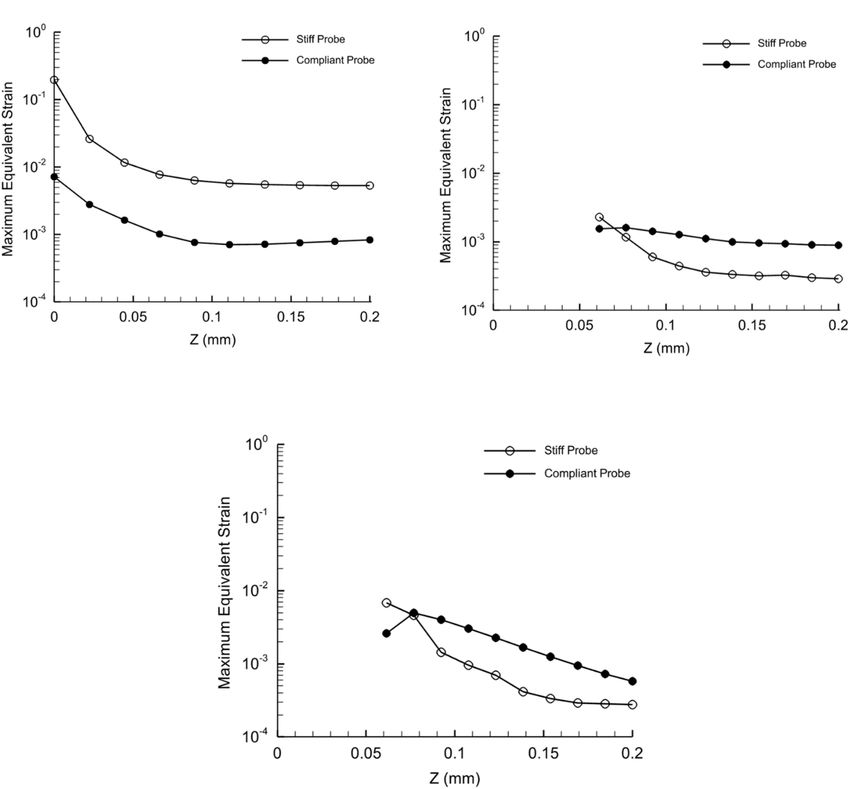
Al Abed et al. Intracortical Implants FEM Simulation
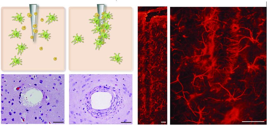
FIGURE 1 | Glial encapsulation of intracortical microelectrode. (A,B) Shows two stages of glial activation where astrocytes and microglial cells are activated and
incapsulate probe at the site of injury. (C,D) The reactive astrocytes, immunohistochemically labeled here for GFAP, encapsulate the neural probes forming a dense
cellular sheath. Figure adapted from Marin and Fernandez (2010). Scale bar = 50 µm.
TABLE 1 | The material properties, dimensions, and boundary conditions for each modeled probe and simulation case.
Case number Implant material Probe dimensions Elastic modulus Poisson ratio Applied displacement in
(µm) (MPa) X-axis direction (µm)
Case 1a Silicon 1125 × 125 × 25 2 × 10⁵ 0.278 1
Case 2a Silicon 1125 × 125 × 25 2 × 10⁵ 0.278 10
Case 3a Silicon 1125 × 125 × 25 2 × 10⁵ 0.278 20
Case 4a Polyimide 1125 × 125 × 25 2.7 × 10³ 0.33 1
Case 5b Hypothetical soft 1125 × 125 × 25 6 × 10⁻³ 0.33 1
Case 6b PVAc-NC 1125 × 125 × 63 12.7 0.3 1
Case 7b PVAc-NC 1125 × 125 × 25 12.7 0.3 1
Case 8b PVAc-NC 1125 × 125 × 25 12.7 0.3 20
a Probe dimensions and material properties are taken from Subbaroyan et al. (2005).
b Probe dimensions and modulus of elasticity are taken from Nguyen et al. (2014) and Poisson ratio from Polanco et al. (2016).
of 0.33; the hypothetical material with an elastic modulus of cranium of the brain. For instance, the rotational acceleration
6,000 KPa, equal to that of the brain tissue, and a Poisson’s of the head could result in the probe being displaced parallel
ratio of 0.33; and lastly, for the compliant probe the material or perpendicular to its axis. To model this, the general brain
was considered to be made of tunicate cellulose nanocrystal movement can be restricted and a fixed boundary condition
(NC) with a PVAc coating dipped in dimethylformamide. This at bottom of the tissue is usually applied to prevent large-
material structure allowed a mechanically adaptive implant with scale global displacements and allow the local displacement
an elastic modulus of 5.2 GPa pre-insertion and 12.7 MPa around the implant [more detailed information can be found
post-insertion, with Poisson’s ratio of 0.38 and 0.3, respectively in Subbaroyan et al. (2005)]. The adhesion properties between
(Capadona et al., 2008; Nguyen et al., 2014). In the simulation, the microelectrode and brain tissue were assumed to be of
the post-insertion values were used for the compliant probe. All good adhesion and the contact type was specified as bonded
material properties for the different probes are summarized in (Subbaroyan et al., 2005). The effect of micromotion can be
Table 1. translated into a displacement of the microelectrode, which
could range from 1 to 20 µm at the electrode surface
Boundary and Loading Conditions (Polanco et al., 2016).
Brain micromotions can lead to tethering forces acting on In this study, the focus was on the tangential tethering
the implant when the implant’s platform is grounded into the force, and it is represented as a displacement load applied
Frontiers in Neuroscience | www.frontiersin.org 3 January 2022 | Volume 15 | Article 727715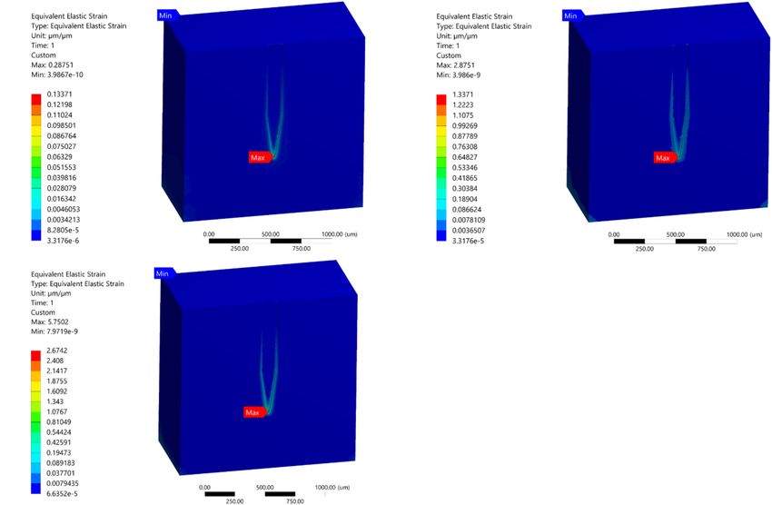
Al Abed et al.                                                                                                             Intracortical Implants FEM Simulation

  FIGURE 2 | Stiff probe and brain tissue geometrical model and dimensions. (A) 3D view; (B) 2D front view.

  FIGURE 3 | Compliant probe and brain tissue geometrical model and dimensions. (A) 3D view; (B) 2D front view.

perpendicularly to the probe axis at the center of the top surface                    strain distribution prediction in the literature, between the model
of the probe, while the edges of the base of the brain tissue were                    of Subbaroyan et al. (2005) and Nguyen et al. (2014), originates
fixed. Figure 4 clarifies the location of the boundary load and the                   from the different loading conditions that was applied on a
fixed supports at the edges of the bottom of the tissue domain.                       silicon-based probe. While for the rest of the different probes,
Different loading conditions of 1 µm, 10 µm, and 20 µm were                           a 1 µm displacement was considered. Table 1 summarizes the
applied on the stiff probe to determine whether the discrepancy in                    different displacements applied for different cases.

Frontiers in Neuroscience | www.frontiersin.org                                   4                                   January 2022 | Volume 15 | Article 727715
Al Abed et al.                                                                                                                 Intracortical Implants FEM Simulation

                                                                                      conducted. The maximum strain values at 4 different test points
                                                                                      (i.e., two points close to the top probe–tissue interface and two
                                                                                      points close to the probe tip–tissue interface) were plotted against
                                                                                      increasing element density for a displacement of 1 µm (Figure 5).
                                                                                      The results of the analysis showed that the variation of maximum
                                                                                      strain as a function of mesh density, in the four monitoring
                                                                                      points, was minimized above 400,000 elements.
                                                                                          Around 5% difference in the maximum Von Mises strain
                                                                                      between 472,937 and the maximum number of elements of
                                                                                      700,000 for stiff probe, and 2% difference in maximum Von Mises
                                                                                      strain between 416,145 and a maximum number of elements of
                                                                                      800,000 for the compliant probe. The maximum strain field at
                                                                                      monitoring points 3 and 4, which are at the top probe-tissue
                                                                                      interface in both stiff and compliant cases remained constant
                                                                                      with the increase of elements number. Thus, for the stiff probe
                                                                                      and compliant probe models, a total of 472,937 and 448,787
                                                                                      tetrahedron elements were used to mesh the domain geometry,
                                                                                      respectively. The skewness and orthogonality for both cases were
                                                                                      kept within the recommended range Ansys Academic Research
                                                                                      Mechanical Biblography: Ansys Academic Research Mechanical,
                                                                                      Release 18.1, User Guide, ANSYS, Inc. The final 3D meshed
  FIGURE 4 | Simulation cases boundary conditions. A tangential load was              domain is shown in Figure 6 with and without a probe.
  applied at the probe’s upper surface and fixed supports defined at the edges
  of the bottom surface of the tissue model (AB, BC, CD, and DA).

                                                                                      SIMULATION RESULTS
Finite Element Analysis                                                               Location of the Highest Strain for the
A three-dimensional finite element model was used to simulate                         Stiff Probe
the probe-brain tissue interface and evaluate the strains formed in                   In the present study, 1, 10, and 20 µm displacements were
the tissue areas surrounding the probe as a function of different                     applied on the top surface of the stiff probe. In all of the three
material properties and two probe sizes (Refer to Figures 2, 3).                      cases, the model predicted that the highest tissue strain was
All of the simulations were performed under static conditions                         always near the bottom tip area of the probe (Figures 7A–C).
and using ANSYS Mechanical Biblography: Ansys Academic            R
                                                                                      The results showed an increase in the strain distribution with
Research Mechanical, Release 18.1. The Von Mises strain output                        the increase in displacement where the maximum prediction of
from the model was used for comparison between simulations.                           elastic strain was 0.287, 2.8751, and 5.7502 for 1, 10, and 20 µm
                                                                                      displacements, respectively.
Domain Meshing
The full model for the brain probe–tissue was discretized with                        Stiff and Compliant Probe Comparison
edge division seeding along the interfaces. A mesh sensitivity                        A comparative analysis between a stiff probe and a compliant
analysis on the stiff and compliant probe geometries was                              probe with two different thicknesses was undertaken to measure

  FIGURE 5 | Mesh sensitivity analysis at a displacement of 1 µm. (A) Stiff silicon probe; (B) compliant PVAc-NC probe.

Frontiers in Neuroscience | www.frontiersin.org                                   5                                       January 2022 | Volume 15 | Article 727715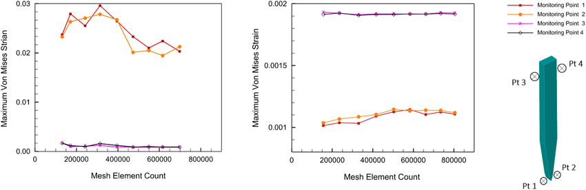
Al Abed et al.                                                                                                                     Intracortical Implants FEM Simulation

  FIGURE 6 | Final mesh half-section view. (A) Without probe; (B) with a probe.

  FIGURE 7 | Mid-section views of the strain distribution for the stiff Michigan probe. (A) 1 µm – Case 1; (B) 10 µm – Case 2; (C) 20 µm – Case 3. The strain is
  concentrated at the tip of the probe and along the contact surfaces for the different loading conditions.

Frontiers in Neuroscience | www.frontiersin.org                                    6                                         January 2022 | Volume 15 | Article 727715
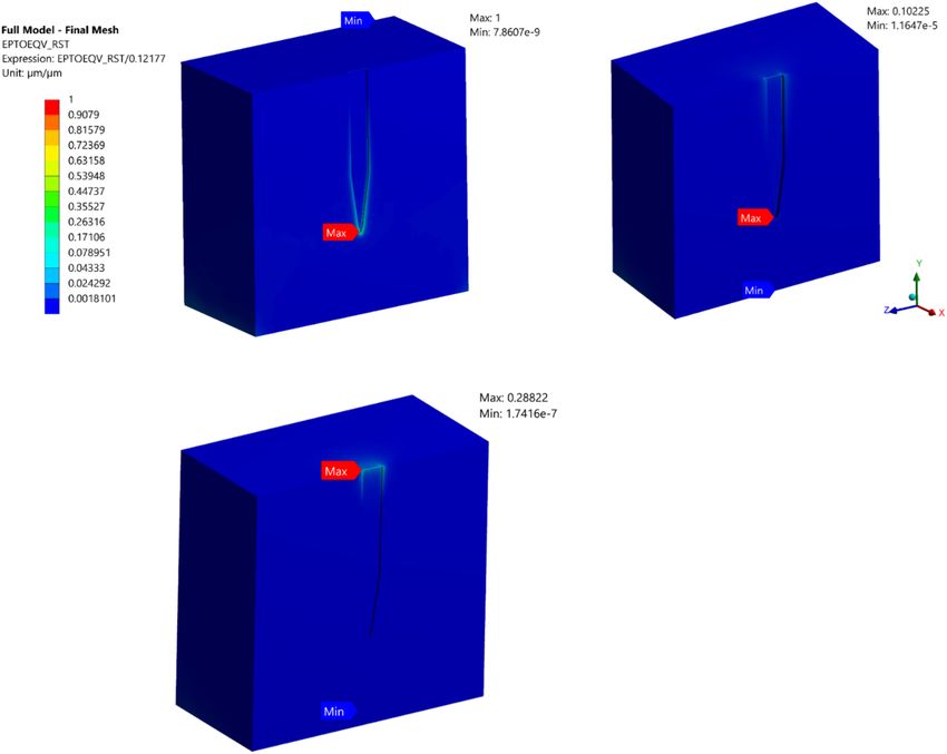
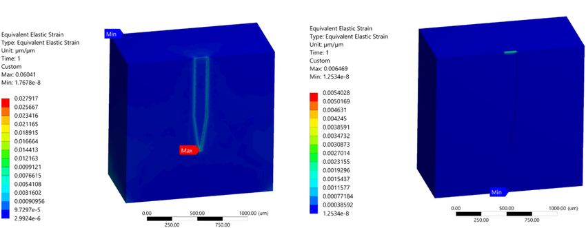
Al Abed et al.                                                                                                                    Intracortical Implants FEM Simulation

and quantify the effect of stiffness and compliant probe                              has most of the strain concentrated on the tip of the probe–
thickness on the strain fields. Stiff and compliant probe                             tissue interface.
strain distributions were acquired at a 1 µm displacement
for three cases (i.e., Case 1, 6, and 7) and the equivalent                           Strain Distribution
strain field distribution was normalized against the equivalent                       To demonstrate the effect of compliant material properties on
strain in the stiff case, which has a value of 0.1217 (i.e.,                          the induced strain distribution, charts of equivalent strain fields
the stiff probe strain outcomes act as a baseline case). The                          for stiff and compliant implants with 63 µm thickness at three
normalized maximum strain decreased drastically to 10.225%                            locations: top, mid-level, and tip section (Refer to Figures 3, 4 for
and 28% for the compliant probe with 63 and 25 µm,                                    the section locations) of the probe were plotted as a function of
respectively, as illustrated in Figures 8B,C. Furthermore, the                        the perpendicular distance to the thickness surface of the probes.
location of the maximum tissue strain was maintained at                               The displacement applied to the probe surface was 20 µm. The
the surrounding tissue area of the tip for the 63 µm thick                            charts show an exponential strain field decaying away from both
compliant probe, while it shifted to the top of the probe                             implants. Moreover, the probe-induced strain spanned up to
surrounding tissue area for the 25 µm compliant probe.                                200 µm from the probe surface. Next to the probe surface,
Additionally, the strain distribution in the two cases of the                         the highest maximum strain for the stiff and compliant were
compliant probe showed a higher concentration at the top of                           0.19 and 0.007, respectively, and they were located at the tip
the probe–tissue interface in comparison to the stiff probe which                     surrounding section. Interestingly, at the top and mid-sections,

  FIGURE 8 | Normalized strain distribution. (A) Stiff probe with thickness = 25 µm – Case 1 in Table 1; (B) compliant probe with thickness = 63 µm – Case 6 in
  Table 1; (C) compliant probe with thickness = 25 µm – Case 7 in Table 1. Strain distributions are normalized to the maximum induced strain surrounding the stiff
  probe of Case 1 in Table 1.

Frontiers in Neuroscience | www.frontiersin.org                                   7                                         January 2022 | Volume 15 | Article 727715
Al Abed et al.                                                                                                                       Intracortical Implants FEM Simulation

65% higher strain magnitudes were predicted away from the                               DISCUSSION
probe surface for the compliant implant compared to that for the
stiff implant (Figure 9).                                                               Brain Micromotion, Probe Displacement,
                                                                                        and Tissue Strain
Polyimide and Hypothetical Probe                                                        Displacement Does Not Affect the Location of
Comparison                                                                              Maximum Strain
Simulation of case 4 indicated that the use of polyimide as                             The maximum strain induced in neural tissue is well accepted as
probe material reduced the magnitudes of maximum strain                                 one of the precursors to the brain’s immune response in the form
fields by up to 81% in comparison with the stiff implant under                          of a glial sheath (Gilletti and Muthuswamy, 2006). In this work,
1 µm displacement. Additionally, the strain distribution with                           we investigated the impact of micromotion of the brain on the
the polyamide probe became more uniform along the tissue-                               magnitude and location of the stain induced in the tissue.
probe interface with the maximum strain predicted at the probe                             Cranial micromotion has been measured and well
tip surrounding region (Figure 10A). On the other hand, the                             documented in the past (Gilletti and Muthuswamy, 2006;
simulation of case 5 showed that for the hypothetical material                          Helton et al., 2011). Micromotion is dominated by the animal
the maximum strain was predicted at the top surface of the                              respiratory and vascular cycle (Gilletti and Muthuswamy, 2006).
tissue probe interface. As expected, when the mismatch in                               A detailed literature search showed that a few groups have
material properties between the probe and the tissue decreased,                         investigated the micromotion of neural probes, most notably
the magnitude of maximum strain was diminished and reached                              Subbaroyan et al. (2005) and Nguyen et al. (2014). The simulation
0.0064 (Figure 10B).                                                                    results of developed models in Subbaroyan et al. (2005) and

  FIGURE 9 | Distribution of the maximum equivalent strain of stiff and compliant probes with respect to distance in Z-axis direction at three different heights. (A) Tip
  of the probe; (B) mid of the probe; (C) top of the probe. The displacement applied on the two probes is 20 µm – Case 3 and 8 in Table 1. Since the thickness of the
  probe differs with height, the predictions in the plot (B,C) start at 62.5 µm from the probe axial axis. Refer to Figures 2, 3 for the height locations. Note that the
  Y -axis values are set to log scale.

Frontiers in Neuroscience | www.frontiersin.org                                     8                                          January 2022 | Volume 15 | Article 727715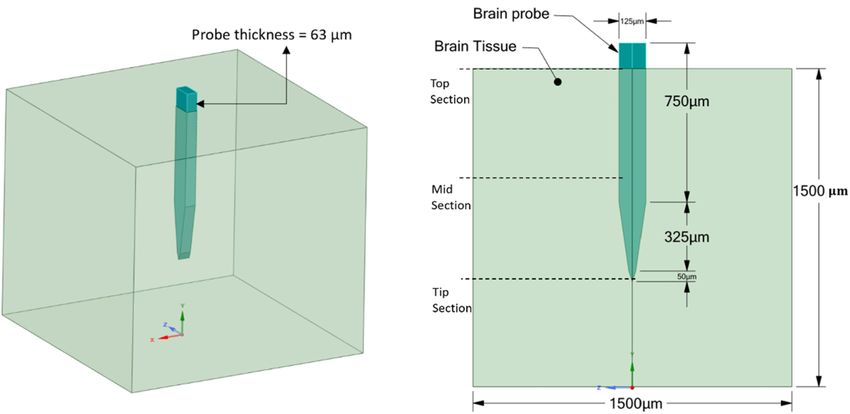
Al Abed et al.                                                                                                                        Intracortical Implants FEM Simulation

  FIGURE 10 | Strain field distribution at probe surroundings tissue region. (A) Polyimide (E = 2.7 GPa); (B) hypothetical soft material (E = 6 KPa).

Nguyen et al. (2014) differed in the location of the maximum                             displacements of brain tissue between 10 and 60 µm, for example,
strain field for probes under displacement. Work done by                                 immediately following the administration of anesthesia (Gilletti
Nguyen et al. (2014) suggested that the strain is maximum                                and Muthuswamy, 2006), does not cause large changes in strain
at the top surface level where the displacement load is being                            beyond 25 µm.
applied. The work by Subbaroyan et al. (2005) found that the                                 On the other hand, our data highlight the large impact of
maximum strain is at the tip of the probe, deep in the brain                             micromotion on the magnitude of strain in the lowest range
tissue. The two studies differed in the amount of displacement                           of 1–10 µm (almost an order of magnitude increase), which
simulated, which were 1 µm and 20 µm for Subbaroyan                                      coincides with both cardiovascular (1–3 µm) and respiratory
et al. (2005) and Nguyen et al. (2014), respectively. Therefore,                         activity (6–10 µm). Also, it is worth mentioning that work
our model investigated the hypothesis that the amount of                                 done on quantifying brain micromotion in anesthetized animals
displacement can account for the difference between the                                  showed that it ranged between 1 and 25 µm for various locations
two predictions in terms of the location of the maximum                                  of implantation in the cortex (Gilletti and Muthuswamy, 2006).
strain. We selected a stiff implant for comparison since it
was simulated in both previous models, and a 1, 10, and                                  Impact of Compliant Probes on Strain
20 µm displacement was applied at the surface of the implant
to determine the maximum strain (Figures 7A–C). The                                      Magnitude and Distribution
finite element model results for all displacement load cases                             Polyimide and Hypothetical Probe
(1, 10, and 20 µm) indicated that for a stiff probe material                             An example of polymers used as a backbone for neural
(i.e., purely silicon), the maximum strain was found to be                               interfaces is polyimide (PI), which is known for its superior
at the tip of the probe–tissue interface irrespective of the                             thermal and chemical resistance, excellent electrical and thermal
magnitude of the displacement. These results match several                               insulation of metallic conductors, biocompatibility, and high
histological studies that support immune response to stiff silicon                       elasticity (Khraiche et al., 2017). That being said, PI still
probes occurring at the tip of the electrode (Stice et al., 2007;                        suffers from a mechanical mismatch with brain tissue due
Stice and Muthuswamy, 2009).                                                             to its high elastic modulus (Bilston, 2011; Almasri et al.,
                                                                                         2020). Our simulation results (Figure 10A) showed that
Strain Beyond 20 µm                                                                      neural probes made of PI will result in a large magnitude
As for the magnitude of the induced strain field, our simulations                        reduction of the strain fields (almost two orders of magnitude).
showed an increase in strain by one order of magnitude                                   In addition, the strain distribution became more uniform
when increasing the displacement from 1 to 10 µm. On the                                 along all the interface edges (Case 4; Figure 10A). On
other hand, for higher displacement over 10 µm the change                                the other hand, our simulations showed that the maximum
in the strain was relatively smaller. In fact, when increasing                           strain occurs at the tip of the probe–tissue interface, which
the displacement from 10 to 20 µm, the model predicted                                   disagrees with the model results of Subbaroyan et al. (2005).
only a 50% increase in the magnitude of the strain. The                                  As for simulations of the hypothetical probe, the results are
characterization of the impact of the full range of micromotion                          not surprising as the softer material has an elastic modulus
on strain helps us better understand the biomechanics of the                             very close to that of brain tissue, which allows for a
implant-tissue interface throughout the life of the implant.                             significant reduction in mechanical mismatch and negligible
Our data suggest that the strain from the large inward                                   strain (Figure 10B).

Frontiers in Neuroscience | www.frontiersin.org                                      9                                          January 2022 | Volume 15 | Article 727715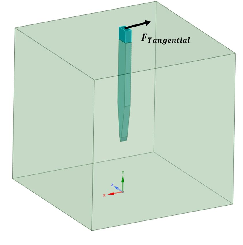
Al Abed et al.                                                                                                   Intracortical Implants FEM Simulation

Polyvinyl Acetate Nanocomposite Probe                                       a promising solution in reducing the effect of micromotions
As previously mentioned, while PI induces less strain compared              on the longevity of the probes (Khraiche et al., 2013b;
to stiffer materials, it still suffers from a mechanical mismatch           Silva Gabriel et al., 2015; Szostak et al., 2017). Recently, a
with brain tissue. With the potential advent of new and more                study on ultrafine microwires bundles interwoven into tabular
compliant materials, we simulated softer and more compliant                 braids showed a significantly less tissue immune response
material probes. PVAc-NC gained attention due to its high                   and more neural survivability than a 50 µm wire (Kim
stiffness prior to insertion (5.2 GPa), which allows tissue                 et al., 2019). They suggest that despite the material modulus
penetration, and then reduced stiffness following implantation to           mismatch between neural tissue and electrode build materials,
∼12 MPa, bringing it much closer to the brain elastic modulus               a geometrical design that is more mechanical compliant
(6,000 KPa) compared to the other probe material. We compared               and with small diameters, such as ultrafine wires, can have
a stiff microelectrode (Case 1; 200 MPa) and a compliant PVAc-              significant improvement in minimizing tissue inflammatory
NC based microelectrode [Case 6; 12.8 MPa; (Nguyen et al.,                  response (Kim et al., 2019). Another interesting design is
2014)] to measure and quantify the effect of the difference                 the mesh electronics–tissue interface, which exhibits almost
in material properties on the strain fields. Stiff and compliant            no chronic immune response up to at least a year post-
electrodes were simulated at 1 µm displacements and found that              injection due to their effective bending stiffness that is
strain was decreased by orders of magnitude for the compliant               comparable to that of the neural tissue (Hong and Lieber,
probe. The normalized maximum strain decreased to 10 percent                2019). However, such designs still face challenges during the
for the compliant electrode, as illustrated in Figure 8 which agrees        insertion as well as being limited by a smaller number of
with the predictions in Nguyen et al. (2014). On the other hand,            recording sites (Hong and Lieber, 2019). Alternatively, new
for the compliant implant (Case 6), the location of the maximum             flexible and wearable sensors consisting of liquid metals are
strain was still at the surrounding region of the probe tip-                being investigated (Ren et al., 2020). They are characterized
tissue interface (10.255%), but most of the strain was distributed          with having excellent flexibility, conductivity, stretchability, and
around the top-tissue interface and with a very close value (i.e.,          precision. Such innovative probes are the focus of our future
approximately 10.1%) to the maximum strain at the tip -tissue               simulations to expand our understanding of their designs and
interface. Additionally, we simulated another compliant implant             possible improvements.
with a thickness of 25 um, similar to the stiff implant thickness,
to determine what would be the effect of fabricating a thinner
compliant implant on strain magnitudes and distribution (i.e.,
Case 7 in Table 1). The model predicted higher maximum strain               CONCLUSION
compared to the thicker implant, indicating that there is more
bending of the probe at the displacement point of application.              Penetrating 3D structures remain a viable approach for
Furthermore, the prediction of the location of the maximum                  recording from the brain for both extracellular and, potentially,
strain shifted to the top agreeing with the results of Nguyen et al.        intracellular recordings (Spencer et al., 2017; Khraiche and
(2014) on compliant implants.                                               El Hassan, 2020). Modeling of the complex tissue/implant
                                                                            biomechanical interaction can help drive developments
Axial Strain Across Probe Body                                              in the design and implantation of microelectrodes in the
                                                                            cortex and could aid in further mitigating the chronic
Based on the axial strain distribution at the tip, mid and surface
                                                                            neuroinflammatory response. In addition, the mechanical
levels of the probe (i.e., perpendicular to the probe thickness)
                                                                            strain has the potential to not only induce immune response
in Figure 9. The values of the strain at the tip decreased in
                                                                            but also neural modulation. Understanding induced strain
the case of compliant in comparison to the stiff implant. Also,
                                                                            conditions can help extend biomechanical neural modulation
the strain dropped sharply below around 5 µm from the probe,
                                                                            models to help better understand its effect on neural excitability
which is in line with the size of the typical glial response to
                                                                            (Tyler, 2012).
the neural probe of approximately 5–10 µm (Spencer et al.,
                                                                               In our work, we simulated the complete range of cortical
2017). Our collected data in Figure 9 and coupled with published
                                                                            motion and its impact on the strain, which had not been
histological data suggest that the distribution of the implant
                                                                            undertaken previously in the literature. This resolves some of the
surrounding strain can be potentially a determinant of the size
                                                                            discrepancies in published data and provides an understanding
of the glial sheath. On the other hand, at the top and mid
                                                                            of the strains induced in the tissue due to the implant for
sections, the compliant implant induced higher strain values
                                                                            the various micromotions. We showed that for a stiff implant,
than the stiff implant as the distance increased (Figure 9).
                                                                            the strain magnitude is dependent on the magnitude of the
Nevertheless, the strain values were very small compared to the
                                                                            displacement, however, the displacement magnitude has no
tip values.
                                                                            impact on the location of maximum strain. Additionally, we
                                                                            examined the effect of several materials of implants on the
New Designs, Challenges, and Future                                         magnitude, location, and distribution of strain. Finally, our data
Direction                                                                   also indicate the potential for using the distribution of the
Current development in probe designs such as microwires, mesh               implant’s surrounding strain as a determinant of the size of
electronics, and polymers, or the micromachining processes are              the glial sheath.

Frontiers in Neuroscience | www.frontiersin.org                        10                                   January 2022 | Volume 15 | Article 727715
Al Abed et al. Intracortical Implants FEM Simulation
DATA AVAILABILITY STATEMENT numerical simulations. MK and JA verified the methods and
supervised the findings of this work. All authors discussed the
The raw data supporting the conclusions of this article will be results and contributed to the final manuscript. All authors listed
made available by the authors, without undue reservation. made an intellectual contribution to the work.
AUTHOR CONTRIBUTIONS FUNDING
AA conceived the presented idea. AA and MK developed This work was supported by Maroun Semaan Research Initiative
the theory and the methodology section. AA performed the and Farouk Jabre Award S20-21.
REFERENCES Lee, H., Bellamkonda, R. V., Sun, W., and Levenston, M. E. (2005). Biomechanical
analysis of silicon microelectrode-induced strain in the brain. J. Neural Eng. 2,
Almasri, R. M., AlChamaa, W., Tehrani-Bagha, A. R., and Khraiche, M. L. 81–89. doi: 10.1088/1741-2560/2/4/003
(2020). Highly flexible single-unit resolution all printed neural interface on Lindner, S. C., Yu, M., Capadona, J. R., and Shoffstall, A. J. (2019). A graphical
a bioresorbable backbone. ACS Appl. Bio Mater. 3, 7040–7051. doi: 10.1021/ user interface to assess the neuroinflammatory response to intracortical
acsabm.0c00895 microelectrodes. J. Neurosci. Methods 317, 141–148. doi: 10.1016/j.jneumeth.
Bilston, L. E. (2011). Neural Tissue Biomecahnics. Berlin: Springer Science & 2019.01.003
Business Media. Mahajan, S., Hermann, J. K., Bedell, H. W., Sharkins, J. A., Chen, L., Chen, K., et al.
Campbell, A., and Wu, C. (2018). Chronically implanted intracranial electrodes: (2020). Toward standardization of electrophysiology and computational tissue
tissue reaction and electrical changes. Micromachines 9:430. doi: 10.3390/ strain in rodent intracortical microelectrode models. Front. Bioeng. Biotechnol.
mi9090430 8:416. doi: 10.3389/fbioe.2020.00416
Capadona, J. R., Shanmuganathan, K., Tyler, D. J., Rowan, S. J., and Weder, Marin, C., and Fernandez, E. (2010). Biocompatibility of intracortical
C. (2008). Stimuli-responsive polymer nanocomposites inspired by the sea microelectrodes: current status and future prospects. Front. Neuroeng.
cucumber dermis. Science 319, 1370–1374. doi: 10.1126/science.1153307 3:8. doi: 10.3389/fneng.2010.00008
Chou, Z., Lim, J., Brown, S., Keller, M., Bugbee, J., Broccard, F. D., et al. (2015). McAlpine, K. (2016). The Michigan Probe: Changing the Course of Brain Research.
Bidirectional neural interface: closed-loop feedback control for hybrid neural Ann Arbor, MI: University of Michigan.
systems. Annu. Int. Conf. IEEE Eng. Med. Biol. Soc. 2015, 3949–3952. doi: Muthuswamy, J., Gilletti, A., Jain, T., and Okandan, M. (2003). “Microactuated
10.1109/EMBC.2015.7319258 neural probes to compensate for brain micromotion,” in Proceedings of
Fomenko, A., Neudorfer, C., Dallapiazza, R. F., Kalia, S. K., and Lozano, the 25th Annual International Conference of the IEEE Engineering in
A. M. (2018). Low-intensity ultrasound neuromodulation: an overview of Medicine and Biology Society (Cancun: IEEE), doi: 10.1109/IEMBS.2003.127
mechanisms and emerging human applications. Brain Stimul. 11, 1209–1217. 9819
doi: 10.1016/j.brs.2018.08.013 Muthuswamy, J., Saha, R., and Gilletti, A. (2005). “Tissue micromotion induced
Gilletti, A., and Muthuswamy, J. (2006). Brain micromotion around implants in stress around brain implants,” in Proceedings of the 3rd Annual International
the rodent somatosensory cortex. J. Neural Eng. 3, 189–195. doi: 10.1088/1741- IEEE EMBS Special Topic Conference on Microtechnologies in Medicine and
2560/3/3/001 Biology, Oahu, HI, 102–103.
Helton, K. L., Ratner, B. D., and Wisniewski, N. A. (2011). Biomechanics of Nguyen, J. K., Park, D. J., Skousen, J. L., Hess-Dunning, A. E., Tyler, D. J., Rowan,
the sensor-tissue interface-effects of motion, pressure, and design on sensor S. J., et al. (2014). Mechanically-compliant intracortical implants reduce the
performance and foreign body response-part II: examples and application. neuroinflammatory response. J. Neural Eng. 11, 56014. doi: 10.1088/1741-2560/
J. Diabetes Sci. Technol. 5, 647–656. doi: 10.1177/193229681100500318 11/5/056014
Hong, G., and Lieber, C. M. (2019). Novel electrode technologies for neural Paralikar, K. J. (2009). Novel Approaches to Quantifying, Tracking and Enhancing
recordings. Nat. Rev. Neurosci. 20, 330–345. doi: 10.1038/s41583-019-0140-6 the Performance of the Electrod - Tissue Interface in Microwire Brain Implants.
Khraiche, M. L., and El Hassan, R. (2020). Advances in three-dimensional College Town, PA: The Pennsylvania State University.
nanostructures for intracellular recordings from electrogenic cells. J. Sci. 5, Polanco, M., Bawab, S., and Yoon, H. (2016). Computational assessment of neural
279–294. doi: 10.1016/j.jsamd.2020.07.003 probe and brain tissue interface under transient motion. Biosensors 6:27. doi:
Khraiche, M. L., El Emam, S., Akinin, A., Cauwenberghs, G., Freeman, W., and 10.3390/bios6020027
Silva, G. A. (2013a). Visual evoked potential characterization of rabbit animal Prange, M. T., and Margulies, S. S. (2002). Regional, directional, and age-dependent
model for retinal prosthesis research. Annu. Int. Conf. IEEE Eng. Med. Biol. Soc. properties of the brain undergoing large deformation. J. Biomech. Eng. 124,
2013, 3539–3542. doi: 10.1109/EMBC.2013.6610306 244–252. doi: 10.1115/1.1449907
Khraiche, M. L., Phillips, W. B., Jackson, N., and Muthuswamy, J. (2017). Sustained Ren, Y., Sun, X., and Liu, J. (2020). Advances in liquid metal-enabled flexible and
elevation of activity of developing neurons grown on polyimide microelectrode wearable sensors. Micromachines 11:200. doi: 10.3390/mi11020200
arrays (MEA) in response to ultrasound exposure. Microsyst. Technol. 23, Silva Gabriel, A., Khraiche Massoud, L., Gert, C., Yu-Hwa, L., Freeman William,
3671–3683. doi: 10.1007/s00542-016-3150-6 R., Somhyung, H., et al. (2015). Integrated Nanowire Array Devices for Detecting
Khraiche, M. L., Silva Gabriel, A., Gert, C., Yu-Hwa, L., Deli, W., and William, and/or Applying Electrical Signals To Tissue. Available online at: https://lens.org/
F. (2013b). Ultra-High Photosensitivity Vertical Nanowire Arrays for Retinal 147-234-566-327-479 (accessed August 2, 2013).
Prosthesis. Available online at: https://lens.org/115-385-809-942-351 (accessed Spencer, K. C., Sy, J. C., Ramadi, K. B., Graybiel, A. M., Langer, R., and Cima, M. J.
July 6, 2011). (2017). Erratum: characterization of mechanically matched hydrogel coatings
Kim, T., Zhong, Y., and Giszter, S. F. (2019). Precise tubular braid structures to improve the biocompatibility of neural implants. sci. Rep. 7:12812. doi: 10.
of ultrafine microwires as neural probes: significantly reduced chronic 1038/s41598-017-12312-8
immune response and greater local neural survival in rat cortex. IEEE Stice, P., and Muthuswamy, J. (2009). Assessment of gliosis around moveable
Trans. Neural Syst. Rehabil. Eng. 27, 846–856. doi: 10.1109/TNSRE.2019.291 implants in the brain. J. Neural Eng. 6:46004. doi: 10.1088/1741-2560/6/4/
1912 046004
Kook, G., Lee, S. W., Lee, H. C., Cho, I.-J., and Lee, H. J. (2016). Neural probes for Stice, P., Gilletti, A., Panitch, A., and Muthuswamy, J. (2007). Thin
chronic applications. Micromachines 7:179. doi: 10.3390/mi7100179 microelectrodes reduce GFAP expression in the implant site in rodent
Frontiers in Neuroscience | www.frontiersin.org 11 January 2022 | Volume 15 | Article 727715Al Abed et al. Intracortical Implants FEM Simulation somatosensory cortex. J. Neural Eng. 4, 42–53. doi: 10.1088/1741-2560/4/ nanowire electrodes on a neural probe. J. Nanotechnol. Eng. Med 2: 2/005 031001. Subbaroyan, J., Martin, D. C., and Kipke, D. R. (2005). A finite-element model of the mechanical effects of implantable microelectrodes in the cerebral cortex. Conflict of Interest: The authors declare that the research was conducted in the J. Neural Eng. 2, 103–113. doi: 10.1088/1741-2560/2/4/006 absence of any commercial or financial relationships that could be construed as a Szostak, K. M., Grand, L., and Constandinou, T. G. (2017). Neural potential conflict of interest. interfaces for intracortical recording: requirements, fabrication methods, and characteristics. Front. Neurosci. 11:665. doi: 10.3389/fnins.2017.00 Publisher’s Note: All claims expressed in this article are solely those of the authors 665 and do not necessarily represent those of their affiliated organizations, or those of Taylor, Z., and Miller, K. (2004). Reassessment of brain elasticity for analysis of the publisher, the editors and the reviewers. Any product that may be evaluated in biomechanisms of hydrocephalus. J. Biomech. 37, 1263–1269. doi: 10.1016/j. this article, or claim that may be made by its manufacturer, is not guaranteed or jbiomech.2003.11.027 endorsed by the publisher. Tyler, W. J. (2012). The mechanobiology of brain function. Nat. Rev. Neurosci. 13, 867–878. doi: 10.1038/nrn3383 Copyright © 2022 Al Abed, Amatoury and Khraiche. This is an open-access article Zhang, W., Ma, Y., and Li, Z. (2016). Numerical simulation of neural probe distributed under the terms of the Creative Commons Attribution License (CC BY). geometry parameters under brain micromotion. Int. J. Appl. Electromagn. Mech. The use, distribution or reproduction in other forums is permitted, provided the 52, 471–477. doi: 10.3233/JAE-162178 original author(s) and the copyright owner(s) are credited and that the original Zhu, R., Huang, G., Yoon, H., Smith, C. S., and Varadan, V. publication in this journal is cited, in accordance with accepted academic practice. No (2011). Biomechanical strain analysis at the interface of brain and use, distribution or reproduction is permitted which does not comply with these terms. Frontiers in Neuroscience | www.frontiersin.org 12 January 2022 | Volume 15 | Article 727715
You can also read