EXTENSION HEADER RAIL HOCHDRUCKERWEITERUNG - EN DE
←
→
Page content transcription
If your browser does not render page correctly, please read the page content below
GCE CENTRAL GAS SYSTEMS

   EXTENSION HEADER RAIL                                                                        EN

   HOCHDRUCKERWEITERUNG                                                                         DE

   E – EXTENSION | T – TEC | L – LOW FLOW

   E – EXTENSION | P – PUR | L – LOW FLOW
   E – EXTENSION | S – SST | L – LOW FLOW

   INSTRUCTION FOR USE
   GEBRAUCHSANLEITUNG

IMPORTANT!
Read carefully before use! Keep the manual for future consultation!
WICHTIG!
Vor Gebrauch sorgfältig lesen!
Bewahren Sie die Gebrauchsanweisung für späteres Nachschlagen auf!
CONTENT
     1 General.......................................................................................................................................................................................... 4
         1.1 information about this instructions manual....................................................................................................................... 4
         1.2 Information about this extension header rail................................................................................................................... 4
         1.3 Explanation of symbols......................................................................................................................................................... 4
EN       1.4 Limitations of liability.............................................................................................................................................................. 5
         1.5 Copyright.................................................................................................................................................................................. 5
         1.6 Spare parts............................................................................................................................................................................... 5
         1.7 Warranty provision.................................................................................................................................................................. 6
         1.8 Customer service.................................................................................................................................................................... 6

     2 Safety............................................................................................................................................................................................ 6
         2.1 Intended use............................................................................................................................................................................ 6
              2.1.1 Structural changes at the extension header rail...................................................................................................... 6
         2.2 Fundamental risks................................................................................................................................................................. 6
         2.3 Operator’s responsibility.......................................................................................................................................................7
         2.4 Personnel requirements....................................................................................................................................................... 8
              2.4.1 Qualifications.................................................................................................................................................................. 8
              2.4.2 Unauthorized personnel............................................................................................................................................ 8
              2.4.3 Training........................................................................................................................................................................... 9
         2.5 Personal protective equipment.......................................................................................................................................... 9
         2.6 Behavior in case of fire or accident.................................................................................................................................10
         2.7 Environmental protection....................................................................................................................................................10
         2.8 Signage...................................................................................................................................................................................10
              2.8.1 Signs that give orders.................................................................................................................................................10
              2.8.2 Signs indicating bans.................................................................................................................................................10
              2.8.3 Warning signs...............................................................................................................................................................10

     3 Technical specifications..................................................................................................................................................11
         3.1 Dimension ETLCP0/ EPLCP0/ ESLCP0.............................................................................................................................11
         3.2 Dimension ETLDSM/ EPLDSM/ ESLDSM........................................................................................................................12
         3.3 Flow scheme ETLCP0/ EPLCP0/ ESLCP0......................................................................................................................13
         3.4 Flow scheme ETLDSM/ EPLDSM/ ESLDSM...................................................................................................................13
         3.5 General information.............................................................................................................................................................14
         3.6 Connection values................................................................................................................................................................15
         3.7 Performance value................................................................................................................................................................15
         3.8 Operating conditions ..........................................................................................................................................................15

     4 Set-up and function...........................................................................................................................................................16
         4.1 Overview ETLCP0/ EPLCP0/ ESLCP0...............................................................................................................................16
         4.2 Overview ETLDSM/ EPLDSM/ ESLDSM..........................................................................................................................16
         4.3 Brief description....................................................................................................................................................................16

     5 Transport, packaging and storage......................................................................................................................... 17
         5.1 Safety information for transportation................................................................................................................................ 17
         5.2 Transport inspection............................................................................................................................................................ 17
         5.3 Packaging............................................................................................................................................................................... 17
         5.4 Storage.................................................................................................................................................................................... 17

                                                                                                      2/52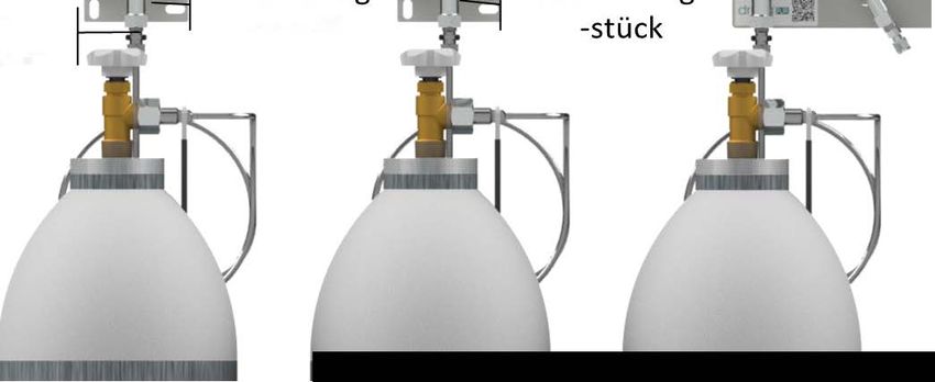
6 Installation and initial start-up....................................................................................................................................18
    6.1 Safety notes for installation and initial start-up..............................................................................................................18
    6.2 Preparation.............................................................................................................................................................................18
    6.3 Preparation and scope of delivery...................................................................................................................................18
    6.4 Installation of tubing and fittings.......................................................................................................................................19
                                                                                                                                                                                                       EN
    6.5 Installation..............................................................................................................................................................................20
        6.5.1 Installation of vent piping...........................................................................................................................................21

7 Operation...................................................................................................................................................................................21
8 Maintenance...........................................................................................................................................................................21
    8.1 Safety notes for maintenance.............................................................................................................................................21
    8.2 Maintenance plan.................................................................................................................................................................21
    8.3 Maintenance work...............................................................................................................................................................22
        8.3.1 Cleaning.........................................................................................................................................................................22
        8.3.2 Requirements for maintenance..............................................................................................................................22
        8.3.3 Necessary maintenance...........................................................................................................................................22
    8.4 Measures following maintenance....................................................................................................................................22

9 Troubleshooting..................................................................................................................................................................23
    9.1 Safety notes for troubleshooting......................................................................................................................................23

10 Dismantling and disposal...........................................................................................................................................23
    10.1 Safety notes for dismantling and disposal....................................................................................................................23
    10.2 Dismantling..........................................................................................................................................................................23
    10.3 Disposal................................................................................................................................................................................24

                                                                                               3/52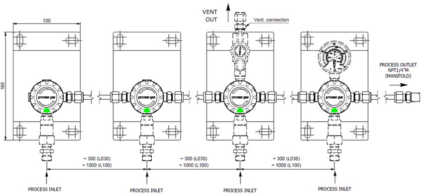
ENGLISH
      INSTRUCTION FOR USE: EXTENSION HEADER RAIL
     1. GENERAL
EN    1.1. INFORMATION ABOUT THIS INSTRUCTION MANUAL
      This instruction is only intended for use with the Extension Header Rails
      • ETLDSMF – Extension TEC-Line Low Flow with Shut-Off Valves
      • ETLCP0C - Extension TEC-Line Low Flow with Connection Piece
      • EPLDSMF – Extension PUR-Line Low Flow with Shut-Off Valves
      • EPLCP0C - Extension PUR-Line Low Flow with Connection Piece
      • ESLDSMF – Extension PUR-Line Low Flow with Shut-Off Valves
      • ESLCP0C - Extension PUR-Line Low Flow with Connection Piece
      This type of Extension Header Rail is suitable to extend the gas inlets of a gas supply manifold.
      These instructions enable to operate the system safely and efficiently. These instructions form an integral part
      of the system and must always be kept with the system and within easy reach of staff.
      Prior to commencing any work, the staff must read these instructions carefully and understand the contents.
      Observance of all the safety information and instructions for operation that are contained in these instructions
      is essential to ensure work safety.
      Local accident prevention regulations and general safety regulations governing the use of the system must
      also be observed.
      Illustrations and images in these instructions serve to ensure a basic understanding of the system and may
      differ from the actual version.

      1.2. INFORMATION ABOUT THIS EXTENSION HEADER RAILS
      Extension Header Rails of this type are only suitable for gases defined as standard gases. The maximum
      working pressure is 300 bar.
      Standard gases for the brass blank version are industrial, inert, flammable and oxidizing gases and/ or their
      mixtures. Not allowed are the components for corrosive and/ or toxic gases and/or their mixtures.
      Standard gases for brass chrome plated version are industrial, inert, flammable and oxidizing gases and/
      or their mixtures. Not allowed are the components for corrosive and/ or toxic gases and/or their mixtures.
      For stainless steel version standard gases are also toxic gases and/ or their mixtures, corrosive gases are
      no allowed.
      When using toxic gases an additional purge gas system is mandatory.
      ETLDSMF/ EPLDSMF/ ESLDSMF: Included is a 4-port shut-off valve with metal diaphragm.

      1.3. EXPLANATION OF SYMBOLS

        SAFETY INFORMATION                       Safety information is highlighted by symbols in these instruc-
                                                 tions. This safety information is preceded by signal words that
                                                 define the extent of risk.
                                                 DANGER!

                                                 This combination of symbol and signal word indicates an im-
                                                 mediately dangerous situation that will cause death or severe
                                                 injury if not avoided.
                                                 WARNING!

                                                 This combination of symbol and signal word indicates a pos-
                                                 sibly dangerous situation that can cause death or severe injury
                                                 if not avoided.
                                                 BEWARE!

                                                 This combination of symbol and signal word indicates a pos-
                                                 sibly dangerous situation that can cause minor injury if not
                                                 avoided.

                                                        4/52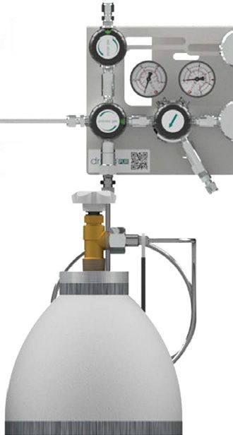
NOTE!

                                           This combination of symbol and signal word indicates a pos-
                                           sibly dangerous situation that can cause property and environ-
                                           mental damage if not avoided.
                                           TIPS AND RECOMMENDATIONS

                                           This symbol highlights useful tips and recommendations, to-
                                                                                                                   EN
                                           gether with help for ensuring efficient and trouble-free opera-
                                           tion.

        SPECIAL SAFETY                     The following symbols are used in the safety information to
                                           draw your attention to particular risks.
         INFORMATION
                                           DANGER!

                                           This combination of symbol and signal word indicates an im-
                                           mediately dangerous situation involving electrical current. Ig-
                                           noring such a warning could result in severe or fatal injuries.

1.4. LIMITATIONS OF LIABILITY
All of the information and notes in these instructions have been compiled in accordance with applicable
standards and regulations. They reflect best engineering practice and our years of experience.
The manufacturer accepts no liability for damages in the following instances:
•  Failure to observe these instructions
•  Utilization of the system for any other than the intended purpose
•  Operation by untrained staff
•  Unauthorized modifications
•  Technical modifications
•  Use of unlicensed spare parts
•  Working with the gas supply panel when any safety device is broken or not functional mounted or safety
   devices don’t work correctly
• Improper control of components, connections and gaskets, which are wearing parts.
• Incorrect reparations
• Violation of temperature limits, which are dedicated in the datasheet during operation or storage
• In case of disaster or force majeure
The actual scope of supply may differ from the explanations and illustrations in these instructions following
the incorporation of new technical changes.
The obligations stipulated in the supply agreement, our general terms and conditions of business, the manu-
facturer’s terms and conditions of supply and the statutory regulations in force at the time of contract conclu-
sion apply.

1.5. COPYRIGHT
The contents of these instructions are protected by copyright. They may be used in connection with the
operation of the system. Any other use above and beyond the aforementioned is only permitted with the
written consent of the manufacturer.

1.6. SPARE PARTS

WARNING!

•   Risk of injury from using incorrect spare parts!
•   The use of incorrect or defective spare parts can result in risks for the operating staff and in damages,
    malfunctions or total failure of the system.
•   Only use original spare parts from the manufacturer or spare parts authorized by the manufacturer.
•   Always consult the manufacturer if in doubt.

LOSS OF WARRANTY

•   The manufacturer’s warranty lapses if unauthorized spare parts are used.

                                                  5/52
1.7. WARRANTY PROVISION
      The warranty provisions are included in the manufacturer’s general terms and conditions of business. See
      chapter VI. Warranty Claims.

      1.8. CUSTOMER SERVICE
      GCE GmbH
EN    Weyherser Weg 8
      DE-36043 Fulda
      +49 (0) 661 8393 -0
      www.gcegroup.com
      service.druva@gcegroup.com
      Please do not hesitate to provide us with information and experiences gained through use; we welcome any
      valuable input that will help to improve our products.

     2. SAFETY
      This section provides an overview of all the important safety aspects to ensure the protection of your staff
      and the safe and trouble-free operation of the equipment. Further safety information relating to specific tasks
      can be found in the sections on the individual life cycle phases.

      2.1. INTENDED USE
      The ETL/ EPL/ ESL Extension Header Rails are only suitable for the defined standard gases and pressures
      observing the given temperature range. The nominal flow is 20 m3/h.
      Intended use also includes compliance with all the information in these instructions and compliance with
      reparation, maintenance working, type label and data sheets.
      Any use other than, or above and beyond, the intended use constitutes improper use.

              WARNING!

      •   Danger from improper use!
      •   Improper use of the system can lead to dangerous situations.
      •   Never use the Extension Header Rail with liquid fluids.
      2.1.1. STRUCTURAL CHANGES AT THE EXTENSION HEADER RAIL
      Without written approval of supplier, no extensions, additions or alternations are allowed on the Extension
      Header Rail.
      Components which are not in perfect condition must be changed immediately.
      Cleaning and disposal of residues.
      Used components which are ready for reparation must be purged with an inert gas before.
      Noise Generation.
      In some cases when specific influence quantities collaborate, e.g. flow and pressure range can cause noise
      generation or the gas itself. If this happens please contact supplier.

      2.2. FUNDAMENTAL RISKS
      The following section addresses the residual risks that may arise, even if the system is used properly. Ob-
      servance of the safety information included below and in other sections of these instructions is mandatory in
      order to reduce the risk of injury and property damage and to avoid dangerous situations.

      DANGER!

      •   Gases can be life threatening!
      •   Gases can supersede the oxygen in air. This can result in death by asphyxiation.
      •   Oxygen produces a strongly oxidizing effect.
      THEREFORE:
      • Enough ventilation is essential
      • Installation only through certified company.
      • Observe ATEX directive.
                                                       6/52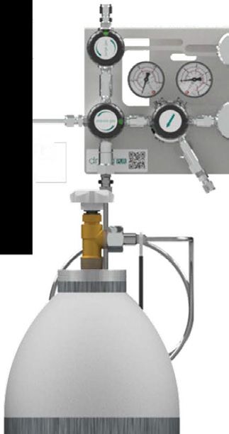
ATTENTION!

•   Risk of injury from environment!
    There can be malfunctions on component due to condensation and/ or icing.
THEREFORE:
• Observe suitable temperatures.
• Protect component from liquids from outside                                                                      EN
• Protect component from dust from outside
• Protect component from weather conditions
• Grounding must be mounted properly
WARNING!

•   Risk of injury from using oil and grease!
    Oil and grease must never be used in gas regulating systems.
    Oil and grease are highly flammable and can react violently to certain pressurized gases
THEREFORE:
• Never use oil and grease
WARNING!

•   Risk of injury from residual energy stored in the system!
If handled incorrectly, pressurized components can move uncontrollably and cause severe injury. If handled
incorrectly or defective, pressurized components can leak gas under high pressure and cause severe or
even fatal injuries.

BEFORE START WORKING WITH THESE COMPONENTS:
• Installation only through certified company.
• Always wear protective goggles when working.
• Always wear ear protection.
• Make sure the equipment is depressurized.
• Make sure the residual energy is discharged.
• Always ensure that gas cannot leak unintentionally.
• Make sure that defective components that are pressurized during operation are immediately replaced by
  trained staff

WARNING!

•   Danger of accident!
    Due to wrong installation there can be serious or even mortal injuries.
THEREFORE:
• During installation the component should be kept safe
• Never throw the component
• Pressurised components are only for intended use.
If there are mechanical damages at tubing or components the whole system must be put in a safe condition.
Affected area must be blocked. Troubles which could influence safety, must be eliminated through qualified
staff or supplier.
Especially with gases failure in pressure regulator could happen. Indications for defective regulator is no flow
or immediately rising outlet pressure. In this case system must be shut-o¬ and the relevant department for
maintenance must be informed. Never close exhaust piping.

2.3. OPERATOR’S RESPONSIBILITY
OPERATOR
The operator is the person who operates the system for commercial or business purposes or who provides
the system for use/application by a third party, and who bears legal product responsibility for protecting the
user, staff or third parties during operation.

OPERATOR’S DUTIES
The system is used for commercial purposes. The operator of the system is therefore subject to legal work
safety obligations.

                                                  7/52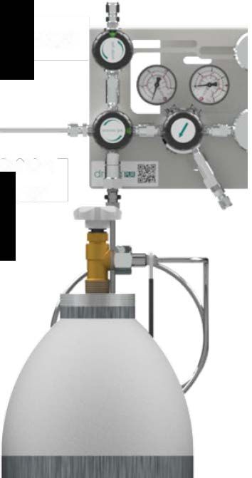
Compliance with the safety, accident prevention and environmental protection regulations that apply for the
     use of the system is mandatory, in addition to the safety information in these instructions.

     THE FOLLOWING APPLIES IN PARTICULAR:
     • The operator must be aware of the applicable work safety regulations and must perform a risk assessment
        to identify risks that may occur as a result of the specific working conditions at the site where the system
        is operated. The operator must use this assessment as the basis for compiling instructions for operating
        the system.
EN   • During the entire period in which the system is operated, the operator must ensure that these operating
        instructions comply with the latest regulations, and must update the instructions if necessary.
     • The operator must assign clear and specific responsibility for installation, operation, troubleshooting,
        maintenance and cleaning.
     • The operator must ensure that all members of staff who work with the system have read and understood
        these instructions. The operator must also ensure that these members of staff are trained at regular inter-
        vals and are aware of the risks.
     • The operator must provide the staff with the requisite protective equipment and bindingly obligate the
        staff to wear the necessary protective equipment.
     In addition, the operator is responsible for ensuring full technical reliability of the system at all times.

     AS SUCH, THE FOLLOWING APPLIES:
     • The operator must ensure compliance with the maintenance intervals specified in these instructions.
     • The operator must ensure that all safety equipment is regularly inspected for functional reliability and
       completeness.

     2.4. PERSONNEL REQUIREMENTS
     2.4.1.QUALIFICATIONS
     The various tasks described in these instructions constitute differing requirements in respect of the qualifica-
     tions of the staff charged with performing these tasks.

     WARNING!

     • Danger if staff is insufficiently qualified!
     • Insufficiently qualified staff is not able to assess the risks associated with the system and expose both
       themselves and others to the risk of severe or fatal injury.
     • Ensure that all works are only performed by staff qualified for the specific task.
     • Keep insufficiently qualified people out of the work area.
     The works must always be assigned only to individuals who can be trusted to perform the works reliably.
     People with impaired reactions, e.g. as a result of drugs, alcohol or medication, must not be allowed to
     perform works.
     These instructions define the qualifications below that are necessary for the respective tasks:

     GAS ENGINEER:
     Have a professional training, skills and experience and the knowledge of the pertinent standards and regula-
     tions to perform works on gas systems and to identify potential hazards. Gas engineers are trained specifi-
     cally for the site where they work and are familiar with all relevant standards and regulations.

     TECHNICIAN
     Have the professional training, skills and experience and the knowledge of the pertinent standards and regu-
     lations to perform the assigned works and to identify and avoid potential hazards.

     2.4.2. UNAUTHORIZED PERSONNEL

     WARNING!

     •   Risks associated with unauthorized personnel in the hazard and work areas can be life threatening!
     •   Unauthorized individuals without the qualifications described in this section are not familiar with the risks
         in the work area. As such, they are in danger of severe or even fatal injury.
     •   Keep unauthorized personnel away from the hazard and work area.
     •   If in doubt, approach individuals and instruct them to leave the hazard and work area.
     •   Stop any work while unauthorized individuals are in the hazard and work area.

                                                        8/52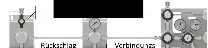
2.4.3. TRAINING
The operator must train the staff at regular intervals. A training log must be maintained for purposes of better
tracking and must contain the following information, at least:
• Date of training
• Names of trained staff
• Contents of the training session
• Name of trainer
• Signatures of the staff members in training and of the trainer                                                   EN
2.5. PERSONAL PROTECTIVE EQUIPMENT
Personal protective equipment protects staff from safety and health hazards while working.
Various tasks on and associated with, the system necessitate the use of personal protective equipment,
which is described in more detail in the individual sections of these instructions.

                         BREATHING APPARATUS

                         To protect against harmful gases, vapors, dust and similar materials and media.
                         Breathing apparatus (e.g. compressed air respirator) must be used when an oxy-
                         gen content of at least 17% in the ambient air is not guaranteed or when the limit of
                         a hazardous substance in the ambient air is exceeded more than 100-fold. Breath-
                         ing apparatus may only be worn by people who have been specially trained in
                         the use.
                         BREATHING APPARATUS, DEPENDENT ON AIR CIRCULATION

                         To protect against harmful gases, vapors, dust and similar materials and media.
                         Breathing apparatus must be worn if a permissible limit is exceeded 100-fold. The
                         breathing apparatus may only be used when the oxygen content in the ambient
                         air measures at least 17%.
                         PROTECTIVE GOGGLES

                         To protect the eyes against airborne parts and splashes of liquid.

                         CHEMICAL-RESISTANT GLOVES

                         To protect the hands from aggressive substances.
                         Make sure the protective gloves are leak-proof before wear, Before taking the
                         gloves off, clean them and then store them in a well ventilated location.
                         PROTECTIVE GLOVES

                         To protect the hands against abrasion, scrapes, pricks or deeper injuries and con-
                         tact with hot or cold surfaces.

                         WEAR HEARING PROTECTION

                         To protect the ears from noise and prevent acoustic trauma

                                                  9/52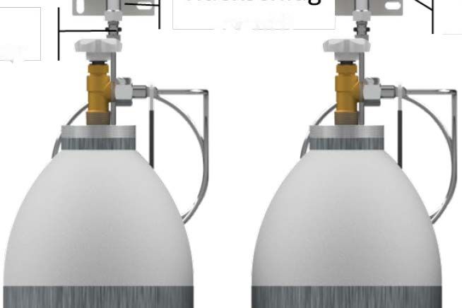
2.6. BEHAVIOR IN CASE OF FIRE OR ACCIDENT
     PREVENTIVE MEASURE
     • Always be prepared for fires and accidents!
     • Always keep first aid equipment (kit, blankets, etc.) and fire extinguishing equipment in working order and
       close to hand.
     • Familiarize the staff with accident reporting, first aid and emergency procedures.
EN   • Keep the access routes free for emergency service vehicles.
     MEASURES IN THE EVENT OF FIRE OR ACCIDENT
     • If there is no risk to your own safety, remove people from the danger zone.
     • Administer first aid if necessary.
     • Notify the fire brigade and/or emergency service.
     • In the event of fire: If there is no risk to your own safety, use fire extinguishing equipment to fight the fire
       until the fire brigade arrives.
     • Inform the person responsible at the location.
     • Make sure the access routes are free for emergency service vehicles.
     • Direct the emergency service vehicles.
     2.7. ENVIRONMENTAL PROTECTION

     NOTE!

     •   Risk of environmental pollution from incorrect handling of environmentally hazardous substances!
     •   The environment can suffer substantial damage if environmentally hazardous substances are handled,
         and especially disposed of, incorrectly.
     •   Always observe the information below on handling environmentally hazardous substances and their dis-
         posal.
     •   Take immediate measures if environmentally hazardous substances are accidentally released into the
         environment. If in doubt, notify the responsible local authorities about the damage and enquire about the
         suitable measures to be taken.

     2.8. SIGNAGE

     WARNING!

     •   Danger from illegible signs!
     •   Labels and signs can gather dirt or become otherwise illegible over time, thus preventing the recognition
         of risks and compliance with the requisite operating information. This could result in injury.
     •   Make sure all safety, warning and operation information is legible at all times.
     •   Immediately replace any damaged signs or labels.
     2.8.1. SIGNS THAT GIVE ORDERS
     •   No signs
     2.8.2. SIGNS INDICATING BANS
     •   No signs
     2.8.3. WARNING SIGNS

            GAS BOTTLES HAZARD                 EXPLOSION - HAZARDOUS               WARNING OF TOXIC AND/ OR
                                                       AREA                         CORROSIVE SUBTANCES

                                                       10/52
3. TECHNICAL SPECIFICATIONS
3.1. DIMENSION ETLCP0/ EPLCP0/ ESLCP0
EN
11/523.2. DIMENSION ETLDSM/ EPLDSM/ ESLDSM
EN
12/523.3. FLOW SCHEME ETLCP0/ EPLCP0/ ESLCP0
Vent Out
Vent Out
PT
PT
5 5 6 6
EN
44
Process Process
3
3 1 – GAS CYLINDER
2 – COIL
2
2 3 – CHECK VALVE
1 4 – CONNECTION PIECE
1 5 – VENT VALVE
6 – GAUGE / PRESSURE
TRANSMITTER
3.4. FLOW SCHEME ETLDSM/ EPLDSM/
Vent Out ESLDSM
Vent Out PT
5 6
PT
5 6
4
Process
4
3 Process
23
1 – GAS CYLINDER
2 – COIL
1
2 3 – CHECK VALVE
4 – SHUT-OFF VALVE
(1 X IN, 3 X OUT)
1
5 – VENT VALVE
6 – GAUGE / PRESSURE
TRANSMITTER
13/523.5. GENERAL INFORMATION
Information ETLCP0CX10FXBTL030/ ETLCP0CX2VFXBTL030/ ETLCP0CX3VFXBTL030/ ETLCP0CX4VFXBTL030/
ETLDSMFX10FXBTL030 ETLDSMFX2VFXBTL030 ETLDSMFX3VFXBTL030 ETLDSMFX4VFXBTL030
Max. Weight [kg] 1,1 2,5 3,5 4,5
Length [mm] 333 630 928 1226
EN
Depth [mm] 67 110 110 110
Height [mm] 221 221 221 221
Information EPLCP0CX10FXBTL030/ EPLCP0CX2VFXBTL030/ EPLCP0CX3VFXBTL030/ EPLCP0CX4VFXBTL030/
EPLDSMFX10FXBTL030 EPLDSMFX2VFXBTL030 EPLDSMFX3VFXBTL030 EPLDSMFX4VFXBTL030
Max. Weight [kg] 1,1 2,5 3,5 4,5
Length [mm] 333 630 928 1226
Depth [mm] 67 110 110 110
Height [mm] 220 220 220 220
Information ESLCP0CX10FXBTL030/ ESLCP0CX2VFXBTL030/ ESLCP0CX3VFXBTL030/ ESLCP0CX4VFXBTL030/
ESLDSMFX10FXBTL030 ESLDSMFX2VFXBTL030 ESLDSMFX3VFXBTL030 ESLDSMFX4VFXBTL030
Max. Weight [kg] 1,1 2,4 3,4 4,3
Length [mm] 333 630 928 1226
Depth [mm] 67 110 110 110
Height [mm] 220 220 220 220
Information ETLCP0CX10FXBTL100/ ETLCP0CX2VFXBTL100/ ETLCP0CX3VFXBTL100/ ETLCP0CX4VFXBTL100/
ETLDSMFX10FXBTL100 ETLDSMFX2VFXBTL100 ETLDSMFX3VFXBTL100 ETLDSMFX4VFXBTL100
Max. Weight [kg] 1,2 2,6 3,7 4,8
Length [mm] 1033 2033 3033 4033
Depth [mm] 67 110 110 110
Height [mm] 221 221 221 221
Information EPLCP0CX10FXBTL100/ EPLCP0CX2VFXBTL100/ EPLCP0CX3VFXBTL100/ EPLCP0CX4VFXBTL100/
EPLDSMFX10FXBTL100 EPLDSMFX2VFXBTL100 EPLDSMFX3VFXBTL100 EPLDSMFX4VFXBTL100
Max. Weight [kg] 1,2 2,6 3,7 4,8
Length [mm] 1033 2033 3033 4033
Depth [mm] 67 110 110 110
Height [mm] 220 220 220 220
Information ESLCP0CX10FXBTL100/ ESLCP0CX2VFXBTL100/ ESLCP0CX3VFXBTL100/ ESLCP0CX4VFXBTL100/
ESLDSMFX10FXBTL100 ESLDSMFX2VFXBTL100 ESLDSMFX3VFXBTL100 ESLDSMFX4VFXBTL100
Max. Weight [kg] 1,2 2,5 3,6 4,7
Length [mm] 1033 2033 3033 4033
Depth [mm] 67 110 110 110
Height [mm] 220 220 220 220
14/523.6. CONNECTION VALUES
Information Value
Process Inlet Connection M14M - METRIC 14X1,5 MALE
N14F - NPT1/4 INCH FEMALE
W2ML - W21,8x1/14" MALE LH
W2MR - W21,8x1/14" MALE RH EN
Vent Connection N14F - NPT1/4 INCH FEMALE
M06B - COMPRESSION METRIC 6 MM BRASS
M08B - COMPRESSION METRIC 8 MM BRASS
M10B - COMPRESSION METRIC 10 MM BRASS
M12B - COMPRESSION METRIC 12 MM BRASS
M06S - COMPRESSION METRIC 6 MM SS
M08S - COMPRESSION METRIC 8 MM SS
M10S - COMPRESSION METRIC 10 MM SS
M12S - COMPRESSION METRIC 12 MM SS
IX4B - COMPRESSION IMPERIAL 1/4 INCH BRASS
IX6B - COMPRESSION IMPERIAL 3/8 INCH BRASS
IX8B - COMPRESSION IMPERIAL 1/2 INCH BRASS
IX4S - COMPRESSION IMPERIAL 1/4 INCH SS
IX6S - COMPRESSION IMPERIAL 3/8 INCH SS
IX8S - COMPRESSION IMPERIAL 1/2 INCH SS
3.7. PERFORMANCE VALUE
Information Value Unit
Nominal flow 20 m3/h
Inlet pressure (max.) 300 bar
3.8. OPERATING CONDITIONS
Information Value Unit
Temperature range -20 till +60 °C
Relative humidity (max.) 98 %
15/524. SET-UP AND FUNCTIONS
4.1. OVERVIEW ETLCP0/ EPLCP0/ ESLCP0
Vent Vent Gauge
EN Vent
Connection Vent
Valve Gauge
Connection Valve
Cross
lnlet Valve Cross
Piece
lnlet
Connection Valve Piece
Connection
Illustrations and images in these instructions serve to ensure a basic understanding of the system and may
differ from the actual version.
4.2. OVERVIEW ETLDSM/ EPLDSM/ ESLDSM
Vent Vent
r=�/1
Connection Valve Gauge
Vent Vent
r=�/1
Connection Valve Gauge
r
r Check Shut-Off
lnlet Valve Valve
Connection Check Shut-Off
lnlet Valve Valve
Connection
Illustrations and images in these instructions serve to ensure a basic understanding of the system and may
differ from the actual version.
4.3. BRIEF DESCRIPTION
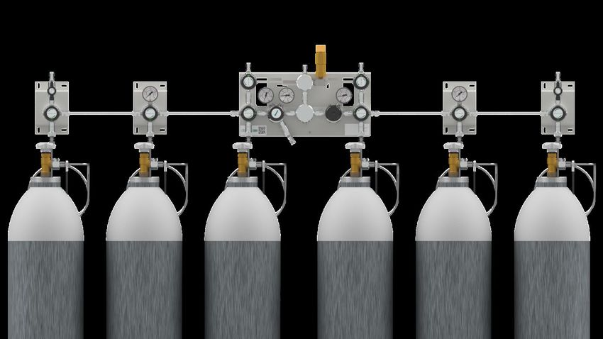
Extension Header Rails are used to increase the number of high-pressure inlet ports for gas supply manifolds.
There can be up to four additional inlet ports per side of the gas supply manifold. They are available in brass
blank, brass chrome plated and stainless steel. As a special there can be check valve and/ or vent valve. As
gauge type you can choose bourdon tube (BT), inductive contact (I1), reed contact (R5) and pressure transmit-
ter (PT or PX (EX)).
16/525. TRANSPORT, PACKAGING AND STORAGE
TIPS AND RECOMMENDATIONS!
• The installation and start- up of this gas supply panel is normally done by the supplier or by authorized
personnel.
• Even though there can be some users or maintenance personnel who care about the packaging. The fol-
EN
lowing notes should be observed accordingly.
5.1. SAFETY INFORMATION FOR TRANSPORTATION
NOTE!
• Damages caused by inappropriate transportation!
• If transported inappropriately, consignments can fall or topple over. This can cause considerable property
damage.
• When unloading the consignments on delivery and transporting them on the premises, act with caution
and observe the symbols and warnings on the packaging.
• Use only the attachment points provided.
• Do not remove the packaging until you are ready to assemble the regulator.
5.2. TRANSPORT INSPECTION
Upon delivery, check immediately that the consignment is complete and has not been damaged during tran-
sit. Procedure on detection of visible transport damage:
• Refuse acceptance of the delivery or only accept subject to reservation
• Record the extent of the damage on the transportation documentation or on the forwarder’s delivery note
• File a complaint
TIPS AND RECOMMENDATIONS!
• Report each and every defect as soon as you discover it. Claims for damages can only be asserted within
the specified periods.
5.3. PACKAGING
The individual consignments are packed according to the anticipated transport conditions. Without exception
all packaging is made of environmentally friendly material.
The packaging is intended to protect the individual components against transport damage, corrosion and
other damage until they are ready for installation. Do not, therefore, destroy the packaging; only remove it
when assembly is imminent.
NOTE!
• Risk of environmental harm through incorrect disposal!
• Packaging materials are valuable raw materials. In many cases they can be re-used or recycled. Incorrect
disposal of packaging materials can harm the environment.
• Dispose of packaging materials in an environmentally compatible manner.
• Observe locally applicable disposal regulations. If necessary, commission a specialist disposal firm.
5.4. STORAGE
Store the packages in the following conditions:
• Do not store outdoors
• Store in a dry and dust-free location
• Do not expose to aggressive media
• Protect from sunlight radiation
• Avoid mechanical jolts
• Storage temperature: 15 to 35 °C
• Relative humidity: max. 60 %
• If storing for longer than 3 months, regularly inspect the general condition of all parts and the packaging.
If necessary re-apply or renew the rust-proofing
17/52TIPS AND RECOMMENDATIONS!
• Some packages may bear labels with storage information that extends beyond these requirements. These
notes should be observed accordingly.
6. INSTALLATION AND INITIAL START-UP
EN
6.1. SAFETY NOTES FOR INSTALLATION AND INITIAL START-UP
STAFF
Installation and initial start-up of the system may only be performed by qualified staff.
6.2. PREPARATION
UNPACKING
• The system components should be removed from their packaging carefully and prudently.
• Additional protective packaging should also be removed.
• Check all components of damages from transport
DEPRESSURIZE
• Depressurize components and purge with inert gas if necessary
• Cut tubing with special tool; avoid contaminations (dirt, cuttings, etc.)
• Check perfect condition of components and purity of connections
6.3. PREPARATION AND SCOPE OF DELIVERY
Illustrations and images are served to ensure a basic understanding of the system and may differ from the
actual version.
Unit A Unit B Unit C Unit D
Components on the plate always refer to smart code.
18/52EN
Remove plastic caps from tubing! 1x Fitting for Process Outlet Connection N14M
Tube Length
L030 – 300 mm
L100 – 1000 mmm
Quantity Tubes & Units
Extension Level 1 – 1 Tube, 1 Unit -> 2 Process Inlets
Extension Level 2 – 2 Tubes, 2 Units ->3 Process Inlets
Extension level 3 – 3 Tubes, 3 Units -> 4 Process Inlets
Extension Level 4 – 4 Tubes, 4 Units -> 5 Process Inlets
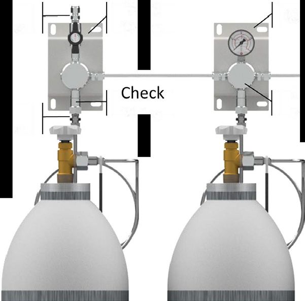
6.4. INSTALLATION OF TUBING AND FITTINGS
Illustrations and images are served to ensure a basic understanding of the system and may differ from the
actual version.
Insert the tube into the tube fitting until it
rests on the shoulder; tighten the nut finger
tight.
High pressure applications with high safety
factor:
Tighten the nut until the tube can no longer
be turned by hand or cannot be moved axi-
ally in the fitting.
Mark the nut at the 6 o'clock position.
19/52Hold the body of the fitting and tighten the
nut to the 9 o'clock position by 1 ¼ turns.
EN
6.5. INSTALLATION
Illustrations and images are served to ensure a basic understanding of the system and may differ from the
actual version.
Connections see point 6.4
Fitting for
Process
Unit A Unit B Unit C Unit D Connection
N14M
UNIT A UNIT B UNIT C UNIT D
Unit with left or right Unit with shut-off Unit with vent valve Unit with gauge or
port plugged valve or cross piece pressure transmitter
Mount Unit A always NEVER mount on Mount Unit C as first Mount Unit D always
on the most left the most left position Unit next to gas sup- as first Unit next to
position, when left (Extension Header ply manifold, when gas supply manifold
port is plugged Rail for left side) you have no Unit (Extension Header
with gauge (Unit D) Rail for right or left
Mount Unit A always NEVER mount on the side)
on the most right most right position Mount Unit C as
position, when right (Extension Header second next to gas
port is plugged Rail for right side) supply manifold,
when you have Unit
with gauge (Unit D)
20/526.5.1. INSTALLATION OF VENT PIPING
Illustrations and images are served to ensure a basic understanding of the system and may differ from the
actual version.
Connections see point 6.4
EN
Unit C
ATTENTION!
• No tilting of the connections during assembly
• Earthing, fuse protection, measurement of the electrical installation by certified company
• Installation of vent piping
After the installation perform leakage test with low pressure before operation.
If there is no leakage perform pressure test with working pressure.
7. OPERATION
BEWARE!
• Valves must always be opened slowly and carefully to prevent pressure surges in the system and damage
to other components!
8. MAINTENANCE
8.1. SAFETY NOTES FOR MAINTENANCE
NOTE!
• Maintenance may only be performed by sufficiently qualified, trained and authorized individuals (see sec-
tion 2.4)
8.2. MAINTENANCE PLAN
The following sections describe the maintenance works that must be performed to ensure the optimum and
trouble-free operation of the regulator.
If regular inspections reveal increased wear, the requisite maintenance intervals must be shortened to reflect
the actual wear and tear.
NOTE!
• Please contact the manufacturer if you have any questions relating to maintenance works and intervals
(see 1.8 for contact details).
21/52Interval Maintenance work Personal
Weekly Check all components visually Competent Person (TRBS 1203)
Every year Checking function & tightness, Competent Person (TRBS 1203)
check for all safety relevant com-
ponents
EN
Every 10 years General overhaul and replace- Competent Person (TRBS 1203)
ment of all wearing parts
8.3. MAINTENANCE WORK
8.3.1. CLEANING
NOTE!
• All cleaning agents must be compatible with the materials of the installed component.
8.3.2. REQUIREMENTS FOR MAINTENANCE
CHECK BEFORE MAINTENANCE START, IF:
• Gas supply is disconnected and safe
• Manifold is depressurized
• Pressure regulator is depressurized
• Valves are closed
• No process gas inside component.
• System is purged and filled with inert gas.
8.3.3. NECESSARY MAINTENANCE
• Check accuracy of pressure gauges
• Manifold, pressure regulator, valve and gauges: check condition, function and labeling
• Check labelling
• Check for corrosion
• Check function
• Pressure test with 1-times working pressure for 12 hours
• Worn and defective components must be changed immediately from authorized qualified company
• Valve is designed according to ISO 10297, including type test with cycle test from up to 2000 cycles.
Change inner parts after 2000 cycles, change must be done from authorized qualified company
• If there are any leakages or too much corrosion at the manifold/ pressure regulator or valve, component
must be replaced with all connections by an authorized company
• After the changing of components or tubes, pressure and leakage test must be done again and be proto-
colled
8.4. MEASURES FOLLOWING MAINTENANCE
THE FOLLOWING STEPS MUST BE PERFORMED WHEN THE MAINTENANCE WORKS HAVE BEEN COM-
PLETED AND BEFORE SWITCHING ON THE SYSTEM.
1. Make sure that all tools, materials and other equipment have been removed from work area.
2. Clean the work area and remove any spilled substances, e.g. liquids, processing material or similar.
3. Make sure that safety relevant components are working perfect.
22/529. TROUBLESHOOTING
The following section describes possible causes of malfunction and how to eliminate them. If malfunctions
occur with increasing regularity, shorten the maintenance intervals to reflect the actual load. If malfunctions
occur that cannot be eliminated with the following help, please contact the manufacturer (see section 1.8 for
contact details).
9.1. SAFETY NOTES FOR TROUBLESHOOTING EN
In any case of malfunction, the shut-off valves oft he connected gas cylinder, gas container or bundle must be
closed. Never operate devices with malfunctions under pressure.
WHAT TO DO IN CASE OF MALFUNCTION:
1. Interrupt and ensure gas supply.
2. Depressurize pressure regulators and close valves.
3. Only trained technical staff may eliminate malfunctions.
4. Restore component to its original state.
Description Reason Solution
No flow Handwheel of shut-off valve Open handwheel slowly
closed
No reaction when turning Defect handwheel because Repair by manufacturer
the handwheel of too high torque, defect of
spindle, defect of thread
This table is not comprehensive. In doubt please contact manufacturer. Contact details section 1.8.
10. DISMANTLING AND DISPOSAL
Once the system has reached its end-of-life, it must be dismantled and disposed of in an environmentally
compatible way.
10.1. SAFETY NOTES FOR DISMANTLING AND DISPOSAL
WARNING!
• Risk of injury through incorrect dismantling!
RESIDUAL ENERGY STORAGE, SHARP EDGED COMPONENTS, TIPS AND CORNERS ON AND IN THE
SYSTEM OR ON THE REQUIRED TOOLS CAN CAUSE INJURY.
• arrange enough space for working
• be careful with sharp edges
• pay attention for order and cleanness
• loose components can cause accidents
• dismantle the components properly. Bear in mind that some of the components are heavy. Use lifting
equipment if necessary
• secure the components against falling or toppling over
10.2. DISMANTLING
PRIOR STARTING DISMANTLING
Depressurize the shut-off valve by turning the handwheel 90°.
Depressurize tubing system and purge with inert gas if neccessary.
Dismantle the assemblies and components properly and in compliance with applicable local work safety and
environmental protection regulations. environmental protection regulations.
At the end devices and components have to be cleaned and disassembled due to valid rules of industrial
safety and environment protection.
23/52WARNING!
• Do not open system filled or used with toxic and/ or corrosive gases.
10.3. DISPOSAL
In the absence of a return or disposal agreement, the dismantled components should be recycled as follows:
Metals: scrap.
EN
Plastics: recycle.
Other components: sort and dispose.
In accordance to Article 33 of REACH GCE, s.r.o. as responsible manufacturer shall inform all customers
if materials containing 0.1% or more of substances included in the list of Substance of Very High Concern
(SVHC).
The most commonly used brass alloys used for bodies and other brass components contain 2-3% of lead (Pb),
EC no. 231-468-6, CAS no. 7439-92-1. The lead will not be released to the gas or surrounding environment
during normal use. After end of life the product shall be scrapped by an authorized metal recycler to ensure
efficient material handling with minimal impact to environment and health.
To date we have no information that indicates that other materials containing SVHC of concentrations
exceeding 0.1% are included in any GCE product.
NOTE!
• Risk of environmental harm through incorrect disposal!
• Incorrect disposal can harm the environment.
• Commission a specialized licensed firm to dispose of electrical waste, electronic components, lubricants
and other auxiliary materials.
• If in doubt, enquire how to ensure environmentally compatible disposal at your local council office or
consult a specialist disposal firm.
MANUFACTURER:
GCE s.r.o. Tel : +420 569 661 111
Zizkova 381 Fax : +420 569 661 602
583 01 Chotebor http://www.gcegroup.com
Czech Republic © GCE s.r.o.
24/52EN 25/52
INHALT
     1 Allgemeines.............................................................................................................................................................................28
         1.1 Information zu dieser Anleitung.........................................................................................................................................28
         1.2 Information zur Hochdruckerweiterung..........................................................................................................................28
         1.3 Symbolerklärung...................................................................................................................................................................28
         1.4 Haftungsbeschränkung.......................................................................................................................................................29
         1.5 Urheberschutz.......................................................................................................................................................................29
         1.6 Ersatzteile...............................................................................................................................................................................29
         1.7 Gewährleistungsbestimmungen.......................................................................................................................................30
DE       1.8 Kundenservice.......................................................................................................................................................................30

     2 Sicherheit.................................................................................................................................................................................30
         2.1 Bestimmungsgemäße Verwendung.................................................................................................................................30
             2.1.1 Bauliche Veränderung an der Hochdruckerweiterung.......................................................................................30
         2.2 Grundsätzliche Gefahren...................................................................................................................................................31
         2.3 Verantwortung des Betreibers.........................................................................................................................................32
         2.4 Personalanforderungen.....................................................................................................................................................32
             2.4.1 Qualifikationen.............................................................................................................................................................32
             2.4.2 Unbefugte.................................................................................................................................................................... 33
             2.4.3 Unterweisung.............................................................................................................................................................. 33
         2.5 Persönliche Schutzausrüstung......................................................................................................................................... 33
         2.6 Verhalten bei Feuerausbruch und bei Unfällen..........................................................................................................34
         2.7 Umweltschutz........................................................................................................................................................................ 34
         2.8 Beschilderung....................................................................................................................................................................... 34
             2.8.1 Gebotzeichen...............................................................................................................................................................34
             2.8.2 Verbotzeichen............................................................................................................................................................34
             2.8.3 Warnzeichen...............................................................................................................................................................35

     3 Technische Daten..............................................................................................................................................................35
         3.1 Massblatt ETLCP0/ EPLCP0/ ESLCP0.............................................................................................................................35
         3.2 Massblatt ETLDSM/ EPLDSM/ ESLDSM.........................................................................................................................36
         3.3 Fliesschema ETLCP0/ EPLCP0/ ESLCP0.......................................................................................................................36
         3.4 Fliesschema ETLDSM/ EPLDSM/ ESLDSM.................................................................................................................... 37
         3.5 Allgemeine Angaben.......................................................................................................................................................... 37
         3.6 Anschlusswerte....................................................................................................................................................................38
         3.6 Leistungswerte.....................................................................................................................................................................38
         3.7 Betriebsbedingungen Umgebung...................................................................................................................................38

     4 Aufbau und Funktion.......................................................................................................................................................39
         4.1 Aufbau ETLCP0/ EPLCP0/ ESLCP0..................................................................................................................................39
         4.2 Aufbau ETLDSM/ EPLDSM/ ESLDSM..............................................................................................................................39
         4.3 Kurzbeschreibung ...............................................................................................................................................................39

     5 Transport, Verpackung und Lagerung...............................................................................................................40
         5.1 Sicherheitshinweise für den Transport............................................................................................................................40
         5.2 Transport Inspektion...........................................................................................................................................................40
         5.3 Verpackung...........................................................................................................................................................................40
         5.4 Lagerung................................................................................................................................................................................40

                                                                                                   26/52
You can also read