Energy Management for Fuel Cell/Battery Hybrid Unmanned Aerial Vehicle
←
→
Page content transcription
If your browser does not render page correctly, please read the page content below
Int. J. Electrochem. Sci., 16 (2021) Article ID: 210919, doi: 10.20964/2021.09.13

 International Journal of
 ELECTROCHEMICAL
 SCIENCE
 www.electrochemsci.org

Energy Management for Fuel Cell/Battery Hybrid Unmanned
Aerial Vehicle
Zhibo Cheng, Huiying Liu, Peiran Yu, Lin Zhu, Tianhao Sun, Yongming Yao*

School of Mechanical and Aerospace Engineering, Jilin University, 130025 Changchun, China
*
 E-mail: ymyao@jlu.edu.cn

Received: 9 May 2021 / Accepted: 28 June 2021 / Published: 10 August 2021

The poor endurance of battery-powered unmanned aerial vehicles (UAVs) can be improved by applying
a fuel cell hybrid system. Energy management can significantly affect the hybrid system performance.
Energy management in fuel cell/battery hybrid fixed-wing UAVs is challenged by the variable flight
conditions of the UAVs and the complex energy flows in the hybrid system. This study first establishes
a mathematical model of the fuel cell/battery hybrid fixed-wing UAV. Next, four energy management
strategies (EMSs), namely fuzzy logic, dynamic programming, Pontryagin’s minimum principle (PMP),
and improved PMP, are proposed. The improved PMP-based EMS considers the fuel cell current and
the power changing rate. The simulation results based on the actual working load of a fixed-wing UAV
in the MATLAB environment show that the proposed EMSs are effective in extending the UAV
endurance while reducing the change rate of the fuel cell output power and improving adverse effects
on the battery lifetime. The methodologies presented herein can be applied to other UAVs and hybrid
systems.

Keywords: fuel cell; hybrid system; energy management; unmanned aerial vehicle; Pontryagin’s
minimum principle.

1. INTRODUCTION

 In the context of the growing demand for unmanned aerial vehicles (UAVs) in military and
civilian applications [1], researchers are placing higher demands on the UAV power system
performance. UAVs powered by internal combustion engines with high power and energy densities have
a satisfactory power performance, but also have the disadvantages of low efficiency [2] and obvious
acoustic and thermal characteristics [3]. Meanwhile, running internal combustion engines consumes
fossil fuel, such as gasoline and diesel fuel, while inevitably emitting greenhouse gases into the
atmosphere. Along with the fossil fuel depletion and the growing importance of environmental
protection, the use of environmentally friendly energy sources such as electric power to replace internal
combustion engines in UAVs is imminent.
Int. J. Electrochem. Sci., 16 (2021) Article ID: 210919 2

 Despite the advantages of electric-powered UAVs with low thermal characteristics and no
polluting gas emissions [4], most of the UAVs currently designed and manufactured by the world’s
major UAV manufacturers, such as DJI-innovations and Parrot, only use batteries to provide the energy
needed for flight. The power performance of these UAVs is limited by the battery performance. A
lithium-ion battery typically has a specific energy of 120–240 Wh/kg and a specific power of 1000–3000
W/kg and can be discharged for 10–60 min [5]. The flight time and the durability of UAVs with batteries
as the sole power source are limited by the poor battery performance. Improving the range of UAVs can
be started by applying a power source with a greater energy density compared to batteries to the UAVs.
 Applying fuel cells in UAVs is a promising method to extend the range. As a different power
source from batteries, fuel cells have the characteristics of high system efficiency, zero-emission
characteristics [6], and ideal power density. Some scholars estimate that with the development of the
hydrogen storage technology, the energy density of fuel cells can reach 1000 Wh/kg [7], which is far
greater than the battery and can effectively improve the range of the power system. Taking HYCOPTER
drones with fuel cells as the main power source, for example, such UAVs can achieve a maximum range
of approximately 3.5 h by adjusting the size of the energy storage unit and the payload weight, to be
much longer than battery-powered UAVs. However, applying fuel cells to UAV power systems faces
the challenges of poor dynamic response and low power density [8], which affect the maneuverability
of UAVs and make fuel cells unsuitable for supplying energy to UAVs in situations where the UAV
power demand changes drastically. In addition, fuel cells cannot absorb and regenerate energy.
 The weaknesses of the fuel cell can be compensated for by forming a hybrid power source
through mixing fuel cells with other power sources [9]. The power system of a hybrid UAV should have
two components: a fuel cell used to provide most of the UAV’s energy requirements and an auxiliary
energy source that can both store electrical energy and release energy. Auxiliary power sources include
batteries, supercapacitors, a combination of both, etc. By combining fuel cells with batteries, a power
source with a better dynamic performance can be realized, and the lack of a dynamic response
performance of fuel cells can be compensated for to form a hybrid system.
 The energy management strategy (EMS) reasonably decides on the power distribution among
multiple power sources according to the different characteristics of multiple components and the power
requirements of different UAV flight phases, thus improving the system efficiency, energy saving, or
other performance. For a hybrid system consisting of a fuel cell and a battery, the output performance of
the hybrid power system affects the fuel cell lifetime [10]. An ideal control strategy can extend the
battery life while reducing the hydrogen consumption [11]. The control strategies currently applied in
hybrid power systems can be summarized into two main categories: rule- and optimization-based
strategies. The rule-based strategy operates the power system in different modes through pre-designed
control rules and compares the parameters of the hybrid power system operation with predefined
parameters. Typical rule-based strategies, such as the state machine strategy [12–14] and the fuzzy logic
[15], have the advantage of low computational cost and is easy to realize online. The disadvantage of
this type of strategy is that the set of rules and parameters depends on the designer’s knowledge of the
load power and different power supply characteristics. Optimization-based strategies achieve energy
management by minimizing predefined objective functions. All of them can be further divided into two
parts: global optimization- and transient optimization-based strategies. Dynamic programming (DP)
Int. J. Electrochem. Sci., 16 (2021) Article ID: 210919 3

[16], Pontryagin’s minimum principle (PMP) [17], and genetic algorithm (GA) [18] are three typical
global optimization algorithms, that bear a large computational burden and are usually used to control
the energy allocation for a specific cycle. Their results can be used as benchmarks to measure the
advantages and disadvantages of other algorithms in energy management. The equivalent consumption
minimization strategy (ECMS) [19,20] and the model predictive control (MPC) [21] are transient
optimization-based energy management methods. Although these algorithms cannot guarantee global
optimality, they have the obvious advantages of being independent of specific operating cycles,
relatively small computational effort, and ease of implementation.
 Multiple methods can be combined or new algorithms can be used to increase the effectiveness
of energy management. Xie et al. [22] proposed a stochastic model predictive controller. The strategy
was more computationally efficient than DP–MPC, did not require a dynamic adjustment of the
equivalence factor compared to the ECMS–MPC, and achieved a near-global optimal performance with
a faster computation. Marzougui et al. [23] proposed an EMS combining three strategies of state machine
strategy, flatness control, and fuzzy logic for a hybrid system. This strategy can regulate the out power
of the fuel cell by fuzzy logic control when the operating conditions are unknown and allocate the power
flow of the battery by relying on a rule-based strategy while allocating the output power of the
supercapacitor by flatness control. Bassam et al. [24] proposed a multiprogram EMS for reducing the
energy consumption of a hybrid powertrain. The strategy was pre-designed with four EMSs, namely
state machine strategy, ECMS, CDCS, and classical PI. The strategy allowed the system to switch
operations between the four different strategies based on the current situation. The proposed
multiprogram EMS was more energy saving compared to the four strategies operating individually.
Zhang et al. [25] proposed a simulation platform that combined the UAV model with a hybrid power
system model and designed a fuzzy state machine-based EMS for it with online application potential.
The control strategy combines the state machine strategy with fuzzy logic to distribute the power flow
among three different power elements. The performed simulations demonstrated that this strategy saves
26.7% of hydrogen fuel compared to the thermostat control strategy, thereby providing better fuel
economy. Rezk et al. [26] proposed two new energy management methods, called the salp swarm and
mine explosion algorithms, and conducted a comparative study of nine different strategies. The salp
swarm algorithm-based external energy maximization strategy showed the highest system efficiency and
the lowest hydrogen consumption.
 The present study investigates the design and analysis of a hybrid power system for UAV
applications. We hope to solve the durability problem of the hybrid system and obtain an attractive
performance using some control strategies. The remainder of this paper is organized as follows: Section
2 presents an analysis of the electrical system topology for a hybrid UAV, including the energy flow
analysis of the hybrid system; Section 3 introduces the four proposed control strategies, namely fuzzy
logic, basic PMP, improved PMP, and DP; Section 4 discusses the simulation of the four proposed
strategies; and Section 5 provides the conclusions of this study.
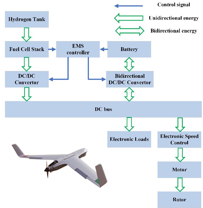
Int. J. Electrochem. Sci., 16 (2021) Article ID: 210919 4

2. SYSTEM DESCRIPTION AND SYSTEM MODEL

 The hybrid UAV topology is analyzed in this section. The energy flows are considered, and the
model of a hybrid-powered UAV is established.

2.1 System description and energy flow analysis

 Fixed-wing UAVs are usually composed of several components, including fuselage, wings,
energy storage system, and powertrain system. The lift and the attitude torque required for the UAV
flight are provided by the wing, which can be further divided into main wings, aileron wings, etc. Figure
1 shows the main components of the proposed UAV hybrid system, which are different from those of a
traditional UAV power system. The unidirectional DC/DC converter has the function of matching
voltage. The bidirectional DC/DC is used to adjust the working current of the battery.

 Unidirectional convertor
 Fuel Cell Stack Electronic speed
 Motor Rotor
 control
 DC Bus

 Energy Storge System Bidirectional convertor

 Other Electronic Loads

 Figure 1. Topology of the hybrid UAV.

 Figure 2 illustrates the energy flows in the hybrid-powered UAVs. Two different energy sources
worked simultaneously in a hybrid-powered system to meet the different power requirements of the
UAV in performing complex missions, whether it is a flat power demand or a drastically changing power
demand. The fuel cell stack was installed to a boost DC/DC converter, while the battery was installed to
a bidirectional DC/DC converter that allowed the current to flow in both directions. As the main energy
source, the changes in the output power of the fuel cell should be limited. The additional energy required
by the UAV during a sudden increase in the power demand should mainly be provided by the battery,
which can also act as an energy storage element to absorb the excess energy released by the fuel cell.
The energy management system regulates the duty cycle of each DC/DC converter by receiving
information, such as load power and battery state of charge (SoC), to control the power of different
power supplies, such that each energy supply operates in the ideal operating state.
Int. J. Electrochem. Sci., 16 (2021) Article ID: 210919 5 Figure 2. Energy flows in the hybrid UAV. 2.2 Fuel cell model The fuel cell is an electrochemical element with many classifications. Among the many types of fuel cells, the polymer electrolyte membrane fuel cell (PEMFC) is believed to be the most promising option for UAV applications [27]. The output voltage of the PEMFC is calculated as follows [28]: = − − − (1) 1 = 1.299 − (8.5 × 10 )( − 298.15) + 4.308 × 10 × × ( ∗2 + 2 ∗2 ) (2) −4 −5 = 1 + 2 ∙ + 3 ∙ ∙ ( ) + 4 ∙ ⋅ ( ∗2 ) (3) ∗ −6 2 = 2 /[5.08× 10 exp(−498/ )] (4) = ⋅ = ⋅ ( + ) (5) ∙ = (6) = (1 − ) (7) where, is the Nernst potential; is the overvoltage caused by activation; is the overvoltage caused by ohmic loss; is the overvoltage caused by concentration losses; T is the operating temperature of the fuel cell; ∗2 is the effective pressure of hydrogen gas; ∗2 is the effective pressure of oxygen; is a parameter measured by the experiment; ∗2 is the oxygen concentration in the liquid phase of the anode; 2 is the partial pressure of oxygen at the cathode; is the fuel cell operating current; is the proton exchange membrane thickness, is the effective area of the proton exchange membrane; is the resistivity of the proton exchange membrane related to the actual operating state of the fuel cell; is a constant determined by the fuel cell and operating state; and is the current density. The overvoltage caused by the fuel cell activation reflects the energy consumed to move the electrons from the cathode to the anode [29]. The overvoltage caused by the ohmic loss of a fuel cell comprises the voltage drop caused by both the equivalent membrane impedance and the
Int. J. Electrochem. Sci., 16 (2021) Article ID: 210919 6
contact impedance between the membrane and the electrode plate , which describes the
impedance of the conductor to the charge when the charge flows in the conductor. Meanwhile, the
overvoltage caused by the concentration loss reflects the voltage drop caused by an untimely supply of
hydrogen and oxygen when the fuel cell current density is too high. Figure 3 shows the output
characteristics of the fuel cell stack (FCS). The PEMFC consumes hydrogen at different rates at different
power outputs, which can be expressed as follows [30]:
= ∙ ∙ 2 ∙ (8)
where, is the number of cells; 2 is the molar mass of hydrogen; is the number of
electrons; and is Faraday’s constant.
Figure 3. Characteristics of a 1000W PEMFC.
2.3 Battery model
A plausible battery model is critical to the study of hybrid system EMSs. We used the PNGV
equivalent circuit model to depict the battery characteristics and the operating current. Figure 4 depicts
the battery equivalent circuit model.
1
2 2
= { − − [( − ) − 4 ∗ ∗ ] }/2 ∗ (9)
where, is the operating current; is the open-circuit voltage; denotes the polarization
effect parameters of the cell; and is the internal resistance. The can be calculated in real time
using the Coulomb counting method.
∗ ( )
( + 1) = ( ) − ⋅ ∆ (10)
Vcell Ecell Vact -Vohm (11)
where, denotes the charging and discharging efficiency of the battery, and denotes the
maximum battery capacity.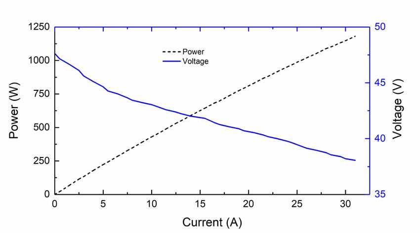
Int. J. Electrochem. Sci., 16 (2021) Article ID: 210919 7 Figure 4. Battery equivalent circuit model. 2.4 DC/DC model In the hybrid-electric propulsion system proposed herein, the fuel cell system and the battery system were installed to the DC bus using two DC/DC converters for precisely control the working conditions of the fuel cells and the batteries. Considering the fast response of the DC/DC converters, the power relationship between the input and the output of the DC/DC converters is described by the efficiency with power loss. The relationship between the power at the input and that in the output of the DC/DC converters is calculated as follows: ( ) = ( ) ∙ − ( ) (12) = ∙ (13) = ∙ (14) where, is the output power of the DC/DC converters; is the input power of the DC/DC converters; is the DC/DC converter efficiency; is the power loss in the DC/DC converters; and are the input voltage and the current, respectively; and and are the output voltage and current, respectively. 2.5 Fixed-wing UAV powertrain model The powertrain of a fixed-wing UAV mainly includes three parts: motor, electronic speed control, and propeller. The powertrain is an important component of the fuel cell hybrid UAV, which receives energy from the energy storage system and converts this energy from electrical into mechanical energy to provide the torque needed for the UAV. ( ) = ( ) ∙ ( ) (15) ( ) = ( ) ∙ ( ) (16) where, is the demand power of UAV; is the motor power; is the motor efficiency; is the motor torque; and is the motor speed. The efficiency of the electronic speed control and the motor is relatively constant during the UAV flight. We assume that the efficiency of the electronic speed control is constant at 90% , while that of the motor is constant at 80%. The motor model is [25].
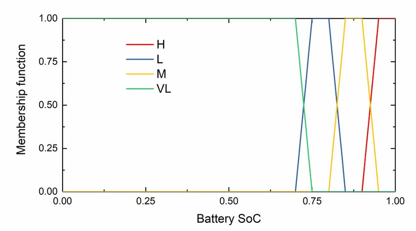
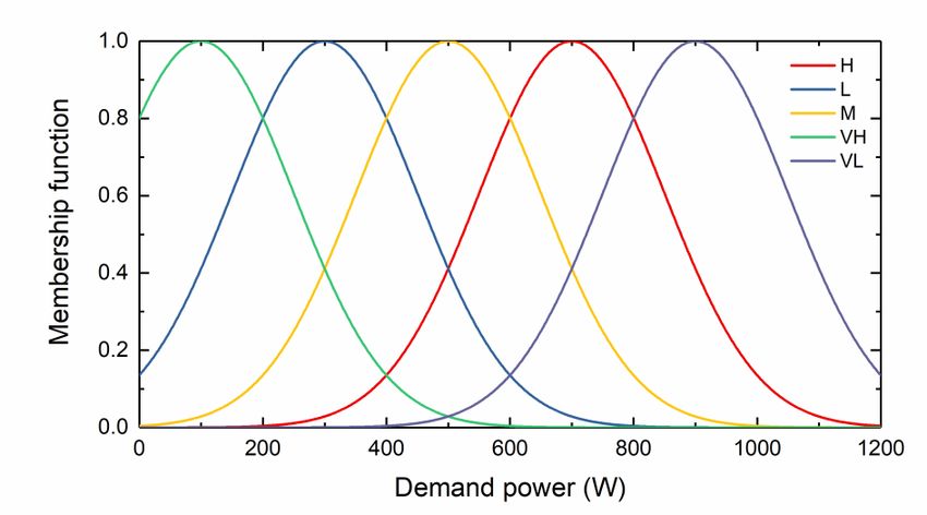
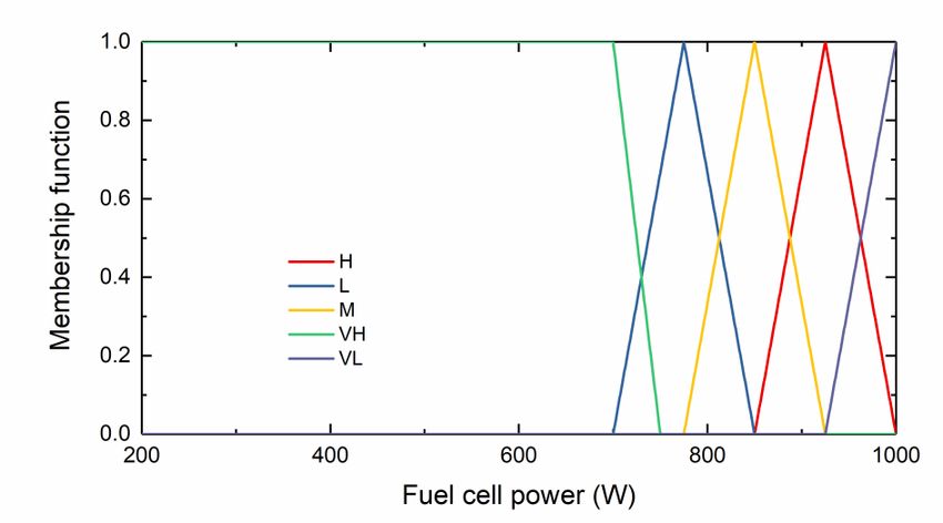
Int. J. Electrochem. Sci., 16 (2021) Article ID: 210919 8 30 = ( − 0 ) ∙ ∙ (17) − / = (18) where, is the motor torque; is the motor current; 0 is the current when the motor has no load; is the speed constant of the motor; is the terminal voltage of the motor; is the motor terminal resistance. The pull and torque generated by the propeller are calculated as follows: 4 = 3 ∙ ∙ 5 ∙ 2 ∙ (19) 4 = 2 ∙ ∙ 4 ∙ 2 ∙ (20) where, is the torque generated by the propeller; is the radius of the propeller; is the propeller speed; is the torque factor of the propeller; and is the pull factor of the propeller. 3. ENERGY MANAGEMENT STRATEGY DEVELOPMENT Energy management must achieve various purposes, including the reduction of the system hydrogen consumption, improvement of the system efficiency, and enhancement of the power source durability to achieve a reasonable power distribution among different power sources. The energy balance equation of the UAV bus is calculated as: ( ) = ( ) + ( ) (21) ( ) = ( ) ∗ 1 + ( ) ∗ 2 (22) where, is the DC bus power for the UAV; is the reference power for the UAV; and 1 and 2 are the energy conversion efficiency of the unidirectional DC/DC and bidirectional DC/DC converters, respectively. 3.1 Fuzzy logic-based EMS The proposed fuzzy logic controller has two input variables and one output variable. The input variables are the power required for the UAV flight and the battery . The output variable is the fuel cell output power . The demand power is divided into five states denoted by very low (VL), low (L), middle (M), high (H), and very high (VH). Table 1. Fuzzy logic rules VL L M H VH H VL VL VL L M M VL VL L H H L L L M H H VL M M H VH VH
Int. J. Electrochem. Sci., 16 (2021) Article ID: 210919 9

 (a)

 (b)

 (c)

Figure 5. Membership functions of the fuzzy logic controller. (a): Demand power; (b): Battery SoC; (a):
 Fuel cell power.
Int. J. Electrochem. Sci., 16 (2021) Article ID: 210919 10
The battery was categorized into four states denoted as very low (VL), low (L), middle (M),
and high (H). was divided into five states: very low (VL), low (L), middle (M), high (H), and very
high (VH). Table 1 presents the rule base of the fuzzy rules, which include 20 rules. Figure 5 shows the
membership functions of , , and . Mamdani’s fuzzy inference approach was used along with
the centroid method for defuzzification.
3.2 PMP-based EMS
As a theory of optimal control, PMP transforms the global optimization problem into a series of
minimal value problems and obtains a sequence of optimal solutions by solving one minimal value
problem at each instant. By adding cost functions or state variables, researchers can use the PMP to
reduce the hydrogen consumption or improve the service life of fuel cells and batteries. The PMP aims
to find the optimal trajectory of the control variable that can reduce the hydrogen consumption,
control the degree of change in the fuel cell power, and maintain the battery SoC within a reasonable
range. A fuel cell/battery hybrid UAV has only one state variable in the system. The equation of state
can be calculated as follows:
̇ ( ) = ( ( ), ( ), )
(23)
1
2 2
− −[( − ) −4∗ ∗ ] }/2∗
̇ =−
= −{ } (24)
̇ ( ) is a function of ( ), ( ) and .
where, the state variable
The excessive depth of the battery discharge will damage the battery’s durability. The battery
SoC must be kept within a reasonable range. When studying the basic PMP, the cost function 1 is
defined to impose constraints on the battery SoC and extend the battery durability, as below:
1 ∙ ( ), ( ) <
2 ∙ ( ), < ( ) <
1 ( ( )) = 0, < ( ) < (25)
3 ∙ ( ), < ( ) <
{ 4 ∙ ( ), ( ) >
where, 1 , 2 , 3 , and 4 are constant tuning parameters, and is the time step.
During the actual UAV flight, the actual power demand dramatically changes, which can easily
cause a drastic change in the fuel cell. Dramatic changes have adverse effects on the fuel cell durability.
Therefore, one must consider limiting the change rate of the fuel cell power. In hybrid UAVs, more
attention should be paid to the durability of the FCS. The changes in the fuel cell power must be
restricted. When the power demand fluctuates, the EMS should control the battery to cope with the
fluctuation while keeping the fuel cell output power relatively stable. The high current density caused
by the excessive fuel cell power is also harmful to the fuel cell durability. The improved PMP constrains
both the fuel cell power variation rate and the fuel cell power by 2 , as follows:
2
2 ( ( )) = 1 ∙ ( ) + 2 ∙ ( ( ) − ( − 1)) (26)
where, 1 and 2 are tuning parameters.Int. J. Electrochem. Sci., 16 (2021) Article ID: 210919 11
The Hamiltonian function of the basic PMP is expressed in formula (27). The Hamiltonian
function of the improved PMP is expressed in formula (28) based on the basic PMP.
( ̇ ( ), ( ), ) = ̇ ( ) + ( ) ∙
̇ ( ) + 1 ( ( )) (27)
2
̇ ( ), ( ), ) = ̇ ( ) + ( ) ∙
( ̇ ( ) + 1 ( ( )) + 2 ( ( )) (28)
2
where, ̇ 2 is the instantaneous hydrogen consumption; and is the co-state variable.
The objective function of the improved PMP consists of four components. The first part is used
to regulate the hydrogen consumption of the fuel cell. The second part is used to control the battery
current. The third part is utilized to maintain the battery SoC within a reasonable range to avoid damage
to the battery’s durability due to overcharging or overdischarging. The fourth part can smooth the output
power curve of the fuel cell by limiting the change of the output power while avoiding the heavy load
output. The Hamiltonian used to solve the optimal control problems is presented as follows:
̇ ∗ ( ) = ( ∗ ( ), ∗ ( ), ∗ ( ))
{ (29)
̇ ∗ ( ) = − ( ∗ ( ), ∗ ( ), ∗ ( ))
( ∗ ( ),
∗ ( ), ∗ ( )) ≤ ( ∗ ( ), ( ), ∗ ( )) (30)
where, ∗ enotes the optimal variable values.
In the proposed hybrid system, limiting the change rate of the fuel cell output power while
imposing constraints on the fuel cell power and the current is beneficial for the fuel cell endurance. This
limiting of the SoC of the battery between [ , ] had a positive effect on prolonging the
battery life. The initial SoC of the battery was set to 0.8. These constraints are summarized as follows:
, ≤ ( ) ≤ ,
0 ≤ ∆ ( ) ≤ ∆ ,
≤ ( ) ≤ (31)
0 = 0.8
{ 0 ≤ ( ) ≤
where, , is the minimum power output of the fuel cell; , is the maximum power
output of the fuel cell;∆ , is the maximum change rate of the fuel cell power; is the
minimum state of charge of the battery; is the maximum state of charge of the battery; and
, is the maximum current of the fuel cell.
3.3 DP-based EMS
The DP solves multi-stage decision problems by processing complex problems in steps. The DP
application must obtain the global information of the UAV flight power in advance. Therefore, the DP
is more suitable as an offline algorithm that serves as a benchmark for other strategies. The objective
function yields by DP is shown below:
( ) = ∑ −1
=0 ( ( ), ( ), ) (32)
2
( ( ), ( ), ) = ̇ 2 ( ) + γ1 ∙ ( ( ) − ) + γ2 ∙ ( ) (33)
where, γ1 and γ2 are constant paraments; and is a pre-designed value of SoC.
The objective function of the DP consists of three parts. The first part imposes constraints on the
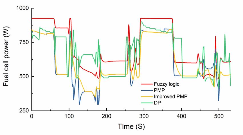
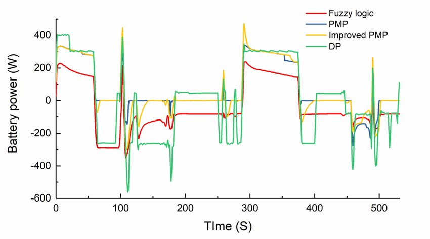
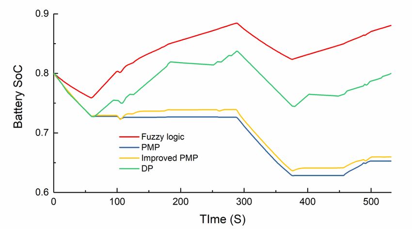
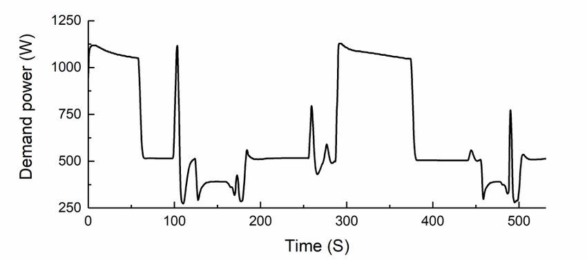
rate of hydrogen depletion in the fuel cells. The second part imposes constraints on the SoC of the battery.Int. J. Electrochem. Sci., 16 (2021) Article ID: 210919 12 The third part can avoid excessive fuel cell current. A set of constraints was established by the PMP. The initial and terminal values of the state variables should be the same during the use of the DP. Bellman’s principle states that the recursive equation solving the objective function of the DP is as follows. ∗ ( ( )) = [ ( ( ), ( ), ) + ∗ +1 ( ( + 1))] = − 1, − 2, … ,1,0 (34) where, ∗ is the optimal solution at the k-th moment and ∗ = 0. 4. RESULTS AND DISCUSSION In this section, the hybrid UAV will be tested in the MATLAB environment using fuzzy logic, basic PMP, improved PMP, and DP-based EMSs. Figure 6 presents the power spectrum of the test UAV from the literature [15]. This section compares the three EMS mentioned in reference [15] using the FL, PMP, improved PMP and DP algorithms. The tuning parameters in the EMSs are set as 1 =-0.02, 2 =- 0.005, 3 =0.005, 4 =0.02, 1=0.0003, 2=0.0005,γ1 =1300,γ2 =0.5. Figures 7–10 show the simulation results of the four strategies for the UAV flight cycle in terms of the fuel cell power, battery power, battery SoC, and change rate of the FCS net power. The simulation results from Figures 7–9 illustrate that the hybrid system based on the proposed strategy can achieve reasonable power splitting under load variation. Figure 8 depicts that the battery can both absorb electrical energy from the fuel cell when the UAV demand power is low and release electrical energy when the UAV is flying under heavy loads. Figure 10 demonstrates that the proposed EMS can effectively reduce the fuel cell power fluctuation in the hybrid system, control the fuel cell operation, and have a protective effect on the FCS life. Figure 6. Power spectrum of a fixed-wing UAV.
Int. J. Electrochem. Sci., 16 (2021) Article ID: 210919 13

 Figure 7. Fuel cell power.

 Figure 8. Battery power.

 Figure 9. Battery SoC.
Int. J. Electrochem. Sci., 16 (2021) Article ID: 210919 14 Figure 10. Fuel cell power changing rate. Table 2. Equivalent hydrogen consumption Equivalent hydrogen EMS consumption (g) Fuzzy logic 5.79 Basic PMP 5.46 Improved PMP 5.48 DP 5.72 Figure 7 show that the change of the fuel cell power under the fuzzy logic-based EMS is neither as drastic as that under the DP strategy nor as smooth as that under the PMP strategy. For example, for a sudden increase in the load power at approximately 260s, the change in the fuel cell output power based on the FL strategy was more obvious than that in the PMP. The fuel cell output power curves of the basic PMP and the improved PMP were the smoothest showing a more consistent trend, which was generally similar. This was because the fuel cell power changing rate was directly limited in the basic PMP, while the improved PMP further constrained the fuel cell power changing rate based on the basic PMP; hence, the fuel cell power of the improved PMP was smoother than that of the basic PMP. Unlike the two PMP-based EMS, DP achieved global optimization. However, the effect of regulating the working conditions of the fuel cell was not good, and the fuel cell output power under the DP strategy drastically fluctuated around 60 s, 120 s, 180 s, 260 s, 400 s, 460 s, and 520 s of the simulation analysis, while the fuel cell output power under the other three strategies was relatively flat. The fuel cell power changing rate data from Figure 10 also verified the above analysis. Figure 8 depicts that the battery power and the change of the battery SoC reflects the change of the battery power. We focused herein on the changing characteristics of the battery SoC. Figure 9 shows that the battery SoC of the hybrid system remained around , which is not higher than the preset or lower than when based on the four different EMSs. The battery SoC variation under four different strategies was influenced by the load situation and had a relatively similar trend. The
Int. J. Electrochem. Sci., 16 (2021) Article ID: 210919 15

battery SoC under all strategies showed a significant decrease within 0–60 s. In the subsequent time
interval of 60–300 s, the battery SoC stopped decreasing and showed a relatively stable or rebounding
trend. The battery SoC decreased again in the 300–380 s interval. The battery was then charged, and the
SoC kept rising. Compared with the PMP, the battery SoC based on the fuzzy logic strategy had a non-
significant decreasing trend in the time interval of 0–60 s and 300–380 s, but showed a more obvious
increase in the time intervals of 60–300 s and 380–530 s. The SoC variation curves under the basic PMP
and improved PMP strategies were close to each other, and overlapped almost completely in the first 60
s of the simulation. They were also very similar in the subsequent simulations. The SoC under the
improved PMP was always slightly higher than that under the basic PMP. Both DP and PMP are global
optimization-based energy management strategies, and the battery SoC based on DP has a very similar
performance to PMP in the 0–60 s time interval. The battery SoC was always between FL and PMP. An
additional point to note is that the battery SoC based on the DP strategy had the same value at the end of
the simulation as at the beginning, while none of the other centralized strategies showed this feature.
 Figure 10 shows the fuel cell power changing rate. The power changing rate of the fuel cell under
the PMP strategy was relatively small, while the variation rate of the fuel cell under the DP strategy was
relatively large. The fuel cell power changed most frequently under the DP strategy, probably because
the DP algorithm cannot impose a constraint on the output power change rate of the fuel cell. In contrast,
the fuel cell power variation rate was effectively controlled under the PMP strategy. The fuel cell output
power variation rate based on the improved PMP was lower than that in the basic PMP because of the
further constraint on the fuel cell output power variation rate imposed by the improved PMP based on
the basic PMP.
 The strategy proposed in this paper was more effective than the strategy proposed in the literature
[15] in maintaining the battery SoC and avoiding the overload output of the fuel cell. Compared with the
online fuzzy strategy in the literature [15] where the battery SoC decreases roughly by 0.25, the fuzzy
logic strategy in this paper had more complex fuzzy rules and the degree of battery SoC fluctuation was
less than 0.1, which can effectively avoid overcharging and discharging of the UAV battery under
complex load conditions and was conducive to improving the battery durability, which was an
outstanding advantage of the FL strategy. Compared to the passive and state machine strategies in [15],
the three strategies proposed in this paper, DP, PMP, and improved PMP, were effective in avoiding the
heavy load output of the fuel cell. The fuel cell operated at close to the rated power based on the passive
and state machine strategies in [15], the strategy proposed in this paper gives the fuel cell the ability to
operated at lower power while using the battery to absorb most of the power fluctuations. For example,
based on the PMP strategy proposed in this paper, the fuel cell only operated at about half of the rated
power at the 200s of the simulation, which had a positive impact on the protection of the fuel cell life.
This is another advantage of the strategy proposed in this paper compared to other strategies.
 Table 2 demonstrates the equivalent hydrogen consumption of the fuzzy logic, PMP, improved
PMP, and DP as 5.79 g, 5.46 g, 5.48 g, and 5.72 g, respectively. The proposed improved PMP-based
EMS can effectively save 5.4 % fuel compared with fuzzy logic. In short, the proposed improved PMP-
based EMS excels fuzzy logic and DP, and approximate to the basic PMP. Thus, the proposed EMS
demonstrates good cost economy and fuel cell power changing rate, confirming its superiority, which
can be converted into an improvement in the fuel cell lifetime and durability.
Int. J. Electrochem. Sci., 16 (2021) Article ID: 210919 16

5. CONCLUSIONS

 This study investigated the EMS of a fixed-wing fuel cell hybrid-powered UAV. First, we
analyzed the energy flows of a fixed-wing UAV powered by a hybrid system. Next, the system
mathematical model of the hybrid UAV was developed. Three EMSs, namely fuzzy logic, DP, and PMP,
were proposed for hybrid UAVs to achieve a reasonable power distribution among different power
sources. The adverse effects of the output current and the power variation rate of the fuel cell on the
lifetime were further considered based on the basic PMP. The simulation results obtained in the
MATLAB environment using an actual load spectrum showed that fuzzy logic was robust and suitable
for real-time control, albeit its hydrogen consumption. DP can be used as an offline evaluation criterion.
PMP-based EMSs are effective in extending the endurance of the UAV while reducing the change rate
of the fuel cell power and improving the adverse effects on the battery lifetime. The improved PMP has
the smallest fuel cell power changing rate, saving 5.4 % hydrogen compared with fuzzy logic, which is
a recommended EMS. The theory proposed herein can be generally applied to various hybrid systems,
which is important for the practical development of UAVs. The fuel cell and battery durabilities in hybrid
UAVs will be investigated in the future.

ACKNOWLEDGEMENT
This work was supported by the Science and Technology Development Project of Jilin Province (Grant
No. 20190303061SF) and the National Natural Science Foundation of China (Grant No. 51805200).

References

1. M. Hassanalian, A. Abdelkefi, Progress in Aerospace Sciences, 91 (2017) 99–131.
2. M. Jaeger, D. Adair, Materials Today-Proceedings, 4 (2017) 4458–4468.
3. M.N. Boukoberine, Z.B. Zhou, M. Benbouzid, Applied Energy, 255 (2019) 22.
4. H.S. Das, M.M. Rahman, S. Li, C.W. Tan, Renewable & Sustainable Energy Reviews, 120
 (2020) 27.
5. A.M. Mazur, R. Domanski, Aircraft Engineering and Aerospace Technology, 91 (2019) 736–
 746.
6. Y. Zhou, A. Ravey, M.C. Pera, Applied Energy, 258 (2020) 17.
7. A. Gong, D. Verstraete, International Journal of Hydrogen Energy, 42 (2017) 21311–21333.
8. T. Lei, Z. Yang, Z. Lin, X. Zhang, Chinese Journal of Aeronautics, 32 (2019) 1488–1503.
9. B. Wang, D. Zhao, W.X. Li, Z.Y. Wang, Y. Huang, Y.C. You, S. Becker, Progress in Aerospace
 Sciences, 116 (2020) 22.
10. X.Q. Lu, Y.B. Wu, J. Lian, Y.Y. Zhang, C. Chen, P.S. Wang, L.Z. Meng, Energy Conversion and
 Management, 205 (2020) 26.
11. N. Sulaiman, M.A. Hannan, A. Mohamed, P.J. Ker, E.H. Majlan, W.R.W. Daud, Applied Energy,
 228 (2018) 2061–2079.
12. C. Liu, Y.J. Wang, L. Wang, Z.H. Chen, Journal of Power Sources, 438 (2019) 13.
13. M.A. Khan, A. Khan, M. Ahmad, S. Saleem, M.S. Aziz, S. Hussain, F.M. Khan, Arabian
 Journal for Science and Engineering, 46 (2021) 1179–1198.
14. S. Al, Y. Xie, K. Malandrakis, M. Lopez, A. Tsourdos, Ieee, 2016 24th Mediterranean
 Conference on Control and Automation, (2016), pp. 1242–1247.
Int. J. Electrochem. Sci., 16 (2021) Article ID: 210919 17

15. X.H. Zhang, L. Liu, Y.L. Dai, T.H. Lu, International Journal of Hydrogen Energy, 43 (2018)
 10094–10103.
16. V. Larsson, L. Johannesson, B. Egardt, Ieee Transactions on Vehicular Technology, 64 (2015)
 1458–1467.
17. K. Ou, W.-W. Yuan, M. Choi, S. Yang, S. Jung, Y.-B. Kim, International Journal of Hydrogen
 Energy, 43 (2018) 15433–15444.
18. S. Ahmadi, S.M.T. Bathaee, A.H. Hosseinpour, Energy Conversion and Management, 160
 (2018) 74–84.
19. H. Li, A. Ravey, A. N’Diaye, A. Djerdir, Journal of Power Sources, 395 (2018) 262–270.
20. Y. Xie, A. Savvaris, A. Tsourdos, Aerospace Science and Technology, 85 (2019) 13–23.
21. T. Li, H. Liu, H. Wang, Y. Yao, Ieee Access, 8 (2020) 25927–25937.
22. S.B. Xie, X.S. Hu, Z.K. Xin, J. Brighton, Applied Energy, 236 (2019) 893–905.
23. H. Marzougui, A. Kadri, J.-P. Martin, M. Amari, S. Pierfederici, F. Bacha, Energy Conversion
 and Management, 195 (2019) 830–843.
24. A.M. Bassam, A.B. Phillips, S.R. Turnock, P.A. Wilson, International Journal of Hydrogen
 Energy, 42 (2017) 623–635.
25. X.H. Zhang, L. Liu, Y.L. Dai, International Journal of Aerospace Engineering, 2018 (2018) 16.
26. H. Rezk, A.M. Nassef, M.A. Abdelkareem, A.H. Alami, A. Fathy, International Journal of
 Hydrogen Energy, 46 (2021) 6110–6126.
27. K. Kaya, Y. Hames, Ieee, A Study on Fuel Cell Electric Unmanned Aerial Vehicle, Ieee, (2019)
 New York.
28. J. Jia, Q. Li, Y. Wang, Y.T. Cham, M. Han, Ieee Transactions on Energy Conversion, 24 (2009)
 283–291.
29. P.R. Pathapati, X. Xue, J. Tang, Renewable Energy, 30 (2005) 1–22.
30. LEI,Tao, MIN,Zhihao, FU,Hongjie, ZHANG,Xingyu, LI,Weilin, ZHANG,Xiaobin,
 Acta Aeronautica et Astronautica Sinica, 41 (2020) 293–307

© 2021 The Authors. Published by ESG (www.electrochemsci.org). This article is an open access
article distributed under the terms and conditions of the Creative Commons Attribution license
(http://creativecommons.org/licenses/by/4.0/).
You can also read