Energy and exergy analysis of a solar/hybrid humidification-dehumidification desalination system
←
→
Page content transcription
If your browser does not render page correctly, please read the page content below
Desalination and Water Treatment 209 (2021) 1–15
January
www.deswater.com
doi: 10.5004/dwt.2021.26508
Energy and exergy analysis of a solar/hybrid humidification–dehumidification
desalination system
Wael Abdelmoez*, Noha M. Sayed, Eman A. Ashour
Department of Chemical Engineering, Faculty of Engineering, Minia University, 61516 Minia, Egypt, Tel. +20 100 0859791;
Fax: +20 86 2346674; emails: drengwael2003@yahoo.com (W. Abdelmoez), noha.mohammed63@yahoo.com (N.M. Sayed),
emanalyashour@yahoo.com (E.A. Ashour)
Received 12 May 2020; Accepted 22 August 2020
abstract
Conventional energy and exergy analyses were performed for solar/hybrid humidification–
dehumidification and heating (HDH) desalination systems. An experimental investigation of HDH
productivity under various operating conditions was also performed. The three major objectives of
this work were to investigate the maximum productivity of solar and hybrid HDH systems, identify
the locations where the largest exergetic destructions occur, and compare the results of conven-
tional energy and exergy analyses. The prototype was constructed and designed in the Solar Energy
Laboratory at the Faculty of Engineering, Chemical Engineering Department, Minia University,
Egypt. It was composed of a flat-plate solar collector (product of Inter Solar Egypt Company, Egypt),
a packed-bed humidifier, dehumidifier, and an additional gas heater. Different experiments were
carried out to identify the factors that influence HDH system performance and exergy destruction,
such as the temperatures and flow rates of air and saline water. The experimental results showed that
the productivity of the system increased with increasing flow rates of air and saline water. The high-
est productivity was 3 and 8.8 kg/h for the solar and hybrid HDH systems, respectively. The exergy
analysis showed that, for the solar heating system, the highest exergetic destruction occurred in
the flat-plate solar collectors. In the hybrid HDH system, the largest exergetic destruction occurred
in the dehumidifier, which can be decreased by increasing the inlet saline water temperature. The
exergetic efficiency of the humidifier was found to be improved by decreasing the inlet saline water
flow rate. In addition, exergetic destruction in the humidifier was reduced by decreasing the inlet
air temperature.
Keywords: Conventional energy analysis; Exergy analysis; HDH; Exergy destruction
1. Introduction efficient, and low-cost desalination technologies. Various
desalination processes, which can be categorized into ther-
The worldwide availability of freshwater is steadily
mal, mechanical, electrochemical, and membrane filtration
decreasing because of climate change, industrialization, and
technologies, have emerged from these efforts.
a dramatic increase in population. In the near future, a large
Among the thermal processes, humidification–dehu-
gap between freshwater demand and supply is expected to
midification technology, which mimics the natural water
develop and to extend to other regions. The desalination of
cycle, is an emergent and promising desalination process.
saline water, which is abundant in seas and oceans, is con-
Humidification–dehumidification and heating (HDH) sys-
sidered the most suitable solution to this future problem.
tems have been developed to operate on the same principles
Accordingly, researchers have been developing optimal,
* Corresponding author.
1944-3994/1944-3986 © 2021 Desalination Publications. All rights reserved.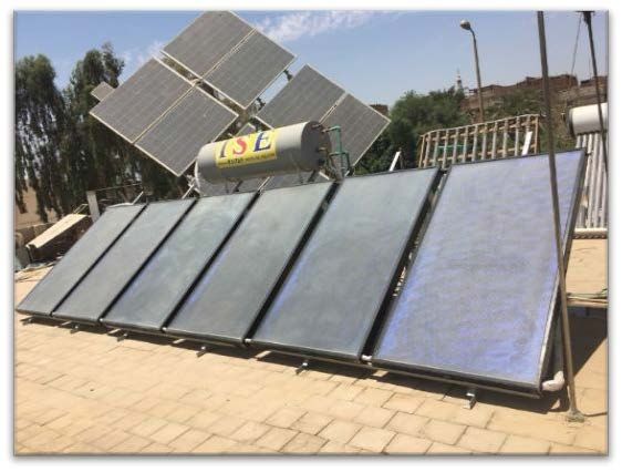
2                             W. Abdelmoez et al. / Desalination and Water Treatment 209 (2021) 1–15

as solar stills; however, the main processes in solar stills are   Maximum freshwater production reached 4,700 mL when
carried out in the same unit, resulting in low system effi-        the airflow rate was 200 kg/h. The freshwater yield increased
ciency. Consequently, in HDH, each process is separated            with increasing mass flow rate of saline water (cooling
into an individual unit, which enhances system productivity        water). The authors found that the freshwater rate increased
and performance [1]. Conventional desalination processes           with the decreasing temperature of the cooling water.
consume a large amount of fossil fuels, thereby generating              El-Shazly et al. [12] investigated which parameters
a large amount of CO2 emissions. To avoid this issue, the          most strongly influence the performance of a solar HDH
use of renewable energy, especially solar energy, is critical.     unit with a packed bed of screens as a humidifier. The pro-
HDH is a simple technology that can be powered by a low-           posed HDH system included a humidifier, dehumidifier,
grade source of energy or by solar energy. In HDH, seawa-          and flat-plate solar collector for heating saline water. The
ter is desalinated by carrying of water vapor using air in a       packed-bed humidifier consisted of plastic screens with a
humidifier. Condensation then occurs in a dehumidifier             bed length of 20–50 cm and a screen thickness of 1 mm. Hot
because of the indirect contact between cold saline water          saline water from the solar collector entered a sprayer at the
and hot humid air, as shown in Fig. 1.                             top of the humidifier and air passed through the packing
    Numerous investigations of the productivity of HDH             from the bottom of the humidifier for air humidification.
systems with various configurations and different energy           The authors stated three objectives. The first objective was
sources have recently been reported [3–10]. For example,           to investigate the performance of the HDH system using an
Lawal et al. [4] used the waste heat from a mechanical vapor       external heating source for heating instead of a solar col-
compression refrigeration cycle (heat pump) to power a             lector. The results indicated that freshwater productivity
HDH desalination unit. They evaluated the influence of             increased with increasing temperature of the inlet saline
various parameters such as the saline water temperature,           water temperature, increasing flow rate, and increasing
feedwater flow rate, feed mass flow rate ratio, and chilled        thickness of the packing materials. The second objective
water temperature. Their results showed that both the feed-        was to define the most effective factors that influenced solar
water temperature and mass flow rate ratio significantly           collector efficiency. The results showed that solar collector
affected the proposed system. The maximum productivity             performance was enhanced when its angle was increased
was 287.8 L/d with a 4.07 gained output ratio (GOR) and            to as high as 45°. The third objective was to investigate
4.86% COP. The cost of freshwater was found to be 10.68            HDH performance under different operating conditions.
to 20.39 USD/m3. Gao et al. [11] used a similar approach to        The results showed that HDH productivity increased as the
investigate the performance of a HDH unit powered by a             inlet water flow rate was increased to 5 L/min and that the
mechanical vapor compression pump. They used a packed-             optimum packed column thickness was 40 cm; however, at
bed humidifier (450 mm × 450 mm × 300 mm) called an                higher flow rates and greater column thicknesses, produc-
alveolate humidifier, which contained a honeycomb paper            tivity decreased. The authors also found that brine recy-
packing material with a large evaporation surface area.            cling to the solar collectors enhanced the HDH productivity
This unit provided two advantages: first, it used a heat-          of 214% compared with that in the absence of recycling.
pump condenser and evaporator as a cooling and heating                  Lawal et al. [8] conducted an investigated to enhance the
source, respectively, resulting in a compact system. Second,       performance of a HDH system operated by a heat pump.
it used solar energy as a clean and low-cost heat source.          A mathematical model based on the first law of thermody-
A mathematical model was judiciously developed for the             namics was developed to predict the efficiency of a closed-
desalination unit based on mass and heat transfer in the           air–open-water (CAOW) water heating cycle and a modified
packed humidifier. The authors investigated the effect of          air-heating cycle coupled with a heat pump. To enhance the
numerous parameters, including the air and water mass              GOR of the system, heat rejected from the condenser was
flow rates and temperatures. The freshwater production rate        used as a heat source in the humidifier. In addition, feed
increased with increasing solar insolation and vice versa.         seawater was cooled via the cooling effect of the evaporator
                                                                   to increase the amount of condensed freshwater. The results
                                                                   showed that the optimum mass flow rate ratio was 0.63 and
                                                                   1.3 with GORs of 8.88 and 7.63, respectively.
                                                                        The effects of various parameters on the performance
                                                                   of HDH systems and evaluations of their performance
                                                                   using conventional energy analysis have been extensively
                                                                   reported [13–21]. However, differences between the types
                                                                   of energy and energy losses due to diminished energy
                                                                   quality have not been investigated. Exergy analysis is a
                                                                   potential tool for analyzing the performance of any ther-
                                                                   mal system. Exergetic (second-law) efficiency is the mea-
                                                                   sure of the effective utilization of energy in the process and
                                                                   depends on both the systems and surroundings. The use
                                                                   of exergetic analysis can provide details about plant com-
                                                                   ponents that can be improved further. This analysis iden-
                                                                   tifies the scope where the maximum energy losses occur
                                                                   and identify where improvement is needed [22]. Hou et al.
Fig. 1. The humidification–dehumidification cycle [2].             [23] conducted exergy analysis of a solar multi-effect HDH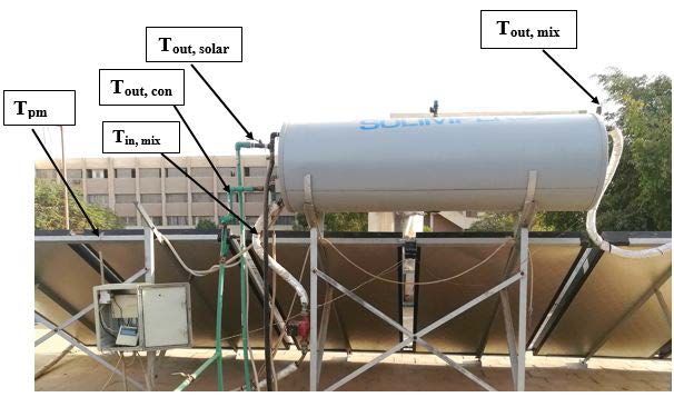
W. Abdelmoez et al. / Desalination and Water Treatment 209 (2021) 1–15                          3

desalination process using pinch technology. The HDH             process and increasing the productivity of the system. Energy
system was composed of two main parts: (1) a wooden              and exergy analyses of the solar heating system and HDH
packed humidifier in which hot saline water was sprayed          system were conducted to evaluate the performance and dif-
and contacted with air introduced by a fan and (2) a con-        ferentiate between these two analyses as well as to identify
denser (dehumidifier). As usual, seawater was fed to the         the components in which major exergy destructions occur.
dehumidifier for preheating and for recovering the latent
heat of condensation; it was then further preheated in a flat-   2. System description
plate solar collector. Hot saline water was sprayed into the
packed-bed humidifier for air humidification, and the air             The proposed system, shown in Figs. 2 and 3, comprises
was cooled in the condenser by transferring the heat to the      two subsystems: (i) a solar collectors cycle and (ii) a HDH
cold saline water, resulting in condensed freshwater. Exergy     cycle. The solar collector cycle consists of six identical
analysis was carried out on the solar multi-effect HDH           flat-plate solar collectors and a heat exchanger. The HDH
desalination process (and could be applied to any thermal        desalination cycle consists of a humidifier (1 m × 0.6 m),
system) for design, optimization, and analysis of the sys-       dehumidifier (0.77 m × 0.54 m), pumps, blower, and an
tem. The results indicated that exergy efficiencies of the       additional gas heater (5 L capacity, butane fuel).
HDH and the solar collector were low; thus, the HDH sys-
tem requires further improvements to increase the exergy         2.1. Humidification–dehumidification desalination process
recovery rate. The solar collector exergy loss was 4.77%, and
the dehumidifier exergy destruction was 5.7%.                         The HDH system investigated in the present work
     To increase understanding of the improvement poten-         (Fig. 4) includes a partial-recycle water-heated, CAOW
tial and optimization of HDH desalination systems, var-          HDH cycle. This cycle differs from the conventional
ious research efforts have been focused on exergy and            heated-water cycle because some of the preheated saline
exergoeconomic analyses. Ghofrani and Moosavi [24] pro-          water that leaves the dehumidifier is recycled to the feed
posed and analyzed three advanced recycling HDHs using           tank. In this way, the moisture in humid air is effectively
energy, exergy, exergoeconomic, and exergo-environmental         condensed because of the maximum temperature differ-
assessments. One of the HDHs was heat-driven, and the            ence between the hot humid air and the cold saline water.
other two were electrically driven systems. Zero liquid dis-     In addition, the portion of the saline water that completes
charge to minimize the negative environmental impact of          the cycle is heated to a higher temperature than in a con-
the desalination system was one of the advantages of this        ventional cycle, leading to an effective humidification pro-
design. A new proposed brine recycling HDH desalination          cess. The preheated saline water then flows through the
system coupled with a heat pump in which the humidifier          solar collectors to increase its temperature through indirect
was positioned before the evaporator was a novel feature         contact with the hot working fluid in the heat exchanger
of the study. The economic study results indicated that          (water–ethylene glycol mixture). In the hybrid HDH sys-
the cost of the proposed system (brine recycle (BR)–HDH–         tem, saline water is further preheated using an additional
heat pump (HP)–evaporator after humidifier (EAH)) was            gas heater. The heated saline water is sprinkled over a cellu-
lower than the costs of the other two systems. However,          losic packing material in the humidifier. The purpose of the
the BR–HDH–HP–EAH system has a lower environmental               packing material is to increase the contact surface area for
impact than the other two systems. Exergy analysis showed        effective mass and heat transfer. Some of the saline water
that the BR–HDH–HP (brine-recycle HDH system driven              evaporates in the air stream and the rest is discharged as
by heat) exhibits the highest second-law efficiency. The         brine from the humidifier bottom. Air is circulated by a
cooler, dehumidifier, and the heater were found to have the      blower from the bottom of the humidifier and through the
highest exergy destructions in the heat-driven system. By        packing materials, where it is heated and humidified as a
contrast, in the electricity-driven system, the compressor,      result of direct contact with the sprayed hot saline water.
expansion valve, and the dehumidifier were the highest           The hot humid air leaves through the top of the humid-
exergy-destructive parts.                                        ifier to the top of the dehumidifier, where it is cooled on
     Kasaeian et al. [25] summarized most of the important       the outer surface of the shell and tube heat exchanger.
studies involving productivity investigations, experimental      The produced freshwater is then collected and measured.
works, mathematical modeling, and exergy and economic
analyses of HDH systems. They made several recommen-
                                                                 2.2. Flat-plate solar collectors
dations for improving the performance and productivity of
the systems, including calling for additional experimental           The solar collector used in the experiments is a prod-
studies of the actual behavior of HDH systems. Moreover,         uct of Inter Solar Egypt Company, Egypt. Six identical flat-
optimization of solar and hybrid desalination processes          plate solar collectors were used for heating the saline water
by considering various process conditions and variables is       (Fig. 5). The system comprises two cycles: the first is the
needed. Thus, the objective of the present work is to inves-     closed cycle, where a mixture of water and ethylene glycol
tigate the maximum productivity of a HDH system under            is heated in the six flat-plate solar collectors, and the sec-
actual experimental conditions. Accordingly, we present          ond is an open cycle, where saline water is heated by indi-
a theoretical investigation of the performance of a par-         rect contact with the mixture in a heat exchanger made of
tial-recycle HDH cycle—specifically, a water-heated, CAOW        304 stainless steel. This innovative setup was designed to
cycle—with the objective of enhancing the condensation           prevent corrosion of the collector materials by saline water.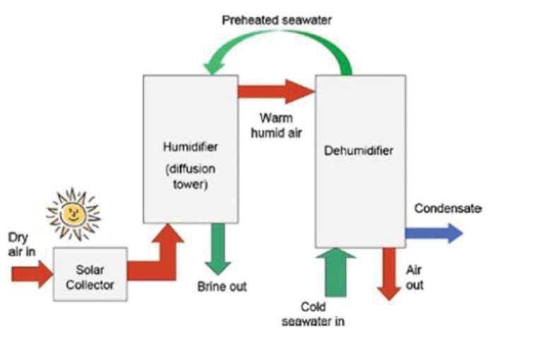
4                           W. Abdelmoez et al. / Desalination and Water Treatment 209 (2021) 1–15

Fig. 2. Schematic of the partial-recycle solar HDH system: (1) feed pump; (2) saline water tank; (3) dehumidifier;
(4) heat exchanger; (5) flat-plate solar collector; (6) humidifier; (7) blower.

Fig. 3. Schematic of the partial-recycle hybrid HDH system: (1) feed pump; (2) saline water tank; (3) dehumidifier; (4) heat
exchanger; (5) flat-plate solar collector; (6) additional gas heater; (7) humidifier; (8) blower.
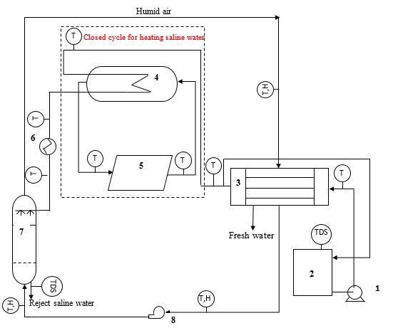
W. Abdelmoez et al. / Desalination and Water Treatment 209 (2021) 1–15 5
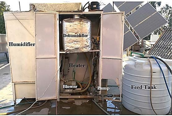
Fig. 4. Schematic and photograph of the experimental setup.
Fig. 5. Photographs of the flat-plate solar collectors.
3. Experimental work In each experiment, the productivity of the system was
measured each hour during the experiment period. Solar
To achieve the objectives of the current work, the per- energy was used as the energy source only in some of the
formance of the proposed HDH system was investigated experiments; the hybrid energy source was used in the
experimentally. Different experiments were designed to others. Two different air blowers with different horse-
study the influence of various parameters on the perfor- power ratings (2 and 3 hp) and different flow rates were
mance of the solar collectors and on HDH productivity. used to study the effect of airflow rates on productivity.
The collector experiments were carried out on August 22,
23, and 24, 2017, in the Chemical Engineering Department
3.1. Uncertainty analysis
of Minia University, Egypt (latitude 28.1194°N, longitude
30.7444°E). HDH experiments were performed during Uncertainty analysis is required to demonstrate the
the period from May to September 2018 at the Faculty of accuracy of experimental work. There are two types of
Engineering, Minia University, Egypt. Inlet and outlet tem- uncertainty: type A and type B. Type A concerns random
peratures of the water in the flat-plate collectors and the heat errors, whereas type B concerns systematic errors that can
exchanger were measured. The inlet and outlet temperatures be evaluated on the basis of the specifications of the used
of saline water in the humidifier and the dehumidifier were measuring tools [26]. The uncertainty of the measured
also measured. In addition, inlet and outlet temperatures values expressed in the present work is exclusively type
and humidity of air in the humidifier and the dehumidi- B. The measured parameters in the experiments include
fier were recorded. Figs. 4 and 5 show all of the positions at the inlet and outlet temperatures of air and water in the
which different temperatures were measured. Temperature humidifier, dehumidifier, and solar collectors, the ambient
readings were recorded every 10 min for 7 h, resulting in temperature, and the solar intensity. K-type thermocouples
43 data points for 12 different measured temperatures. with ±3°C accuracy were used for measuring temperatures.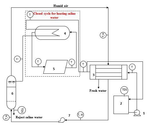
6 W. Abdelmoez et al. / Desalination and Water Treatment 209 (2021) 1–15
A solar power meter (model SPM-1116SD) with an accuracy −1
of ±10 W/m2 was used to measure solar irradiance.
N 1
4. Mathematical model Ut = + +
hw
( )
e
C T −T
We modeled the proposed HDH system presented in pm a
Fig. 4 under the following assumptions: Tpm (N + f )
• The conditions are in a steady-state. ( 2
σ Tpm + Ta Tpm )(
+ Ta2 )
• Heat transfer to the surroundings can be neglected. 2 N + f − 1 + 0.133ε p
1
• Kinetic and potential energy changes can be neglected. + −N (9)
• No work transfer occurs between the system and the ε p + 0.00591Nhw εg
environment.
• The gas behaves as an ideal gas. f = (1 + 0.089hw – 0.1166hwεp)(1 + 0.07866N)
4.1. Solar system where C = 520(1 – 0.000051B2); e = 0.430(1 – 100/Tpm).
4.1.1. Flat-plate solar collectors hw = 5.7 + 3.8VR [29] (10)
4.1.1.1. Energy analysis
K
Under the assumption of steady-state conditions, the Ub = (11)
L
energy balance equation indicates that the useful energy
output of the flat-plate solar collector is equal to the differ-
ence between the solar energy absorbed by the collector and kl Ae [28] (12)
Ue =
thermal losses. Le Ap
Qg = Ac IT (1) The first-law efficiency of the collector is defined as the
ratio between the actual heat gain and the incident solar
energy [30]:
(
Ql = AcU L Tpm − Ta ) (2)
Qu
ηI = (13)
Qu = Qg − Ql (3) IT Ac
4.1.1.2. Exergy analysis
( (
Qu = Ac S − U L Tpm − Ta )) (4)
Exergy is the maximum amount of useful work that can
where be obtained from a reversible process in which a given sys-
tem reaches equilibrium with a defined environment [31].
Exergy can be classified into two types: thermomechanical
−S = ( τα ) IT (5)
and chemical exergy. The thermomechanical exergy can
be defined as the maximum amount of work that can be
Importantly, the heat-removal factor FR is defined as the
obtained from the system when the temperature (T) and
ratio between the actual useful energy gain if the whole col-
pressure (P) of the system differ from the temperature (To)
lector surface is at the inlet fluid temperature and the useful
and pressure (Po) of the environment. The chemical exergy
energy gain:
can be defined as the maximum theoretical work that can
be obtained from the system when the concentration (W) of
p (Tfo − Tfi )
mC each component in the system differs from its concentration
FR = (6) (Wo) in the environment at environment temperature and
(
Ac S − U L (Tfi − Ta ) ) pressure [32].
The general exergy balance equation can be written in the
Thus, the maximum possible useful energy equal to the following form [28]:
actual energy gain:
Exin − Ex s − Exout − Exd = 0 (14)
(
Qu = Ac FR S − U L (Tfi − Ta ) ) (7)
where Exin is the inlet exergy rate, Exs is the stored exergy
rate, Exout is the outlet exergy rate, and Exd is the exergy loss
where UL is the overall heat-loss coefficient, which is the sum
rate.
of the top heat-loss coefficient Ut, bottom heat-loss coefficient
Under steady-state conditions, stored exergy rate Exs = 0;
Ub, and edge heat-loss coefficient Ue [28].
thus, the exergy destruction equation can be expressed as:
U L = Ut + Ub + U e (8) Exd = Exin − Exout (15)W. Abdelmoez et al. / Desalination and Water Treatment 209 (2021) 1–15 7
The inlet exergy rate is the sum of the inlet exergy Exout , f − Exin , f
carried by the fluid and exergy radiation from the sun. ηII = (24)
The inlet exergy rate carried by the fluid is expressed as: T
IT Ac 1 − a
Ts
T
Exin , f = mC
p Tfi − Ta − Ta ln fi (16)
T 4.1.2. Shell and tube heat exchanger
a
4.1.2.1. Energy analysis
Exergy radiation from the sun is expressed as:
Useful energy absorbed by the fluid can be calculated
T from the following equation [33]:
Exin ,Q = IT Ac 1 − a (17)
Ts
Qu , h = mC (
p Tf , o − Tf ,i ) (25)
The exergy rate outlet carried by the fluid flow is
given as: First-law efficiency of the heat exchanger:
T Qu , h
Exout , f = mC
p Tfo − Ta − Ta ln fo (18) ηI = (26)
T Qu
a
Overall energetic efficiency of the solar heating system:
Exergy analysis enables the calculation of exergy losses
due to heat loss from the absorber plate to the environment,
Qu , h
exergy destruction due to temperature differences between ηI = (27)
the sun and absorber plate, exergy destruction due to radi- IT Ac
ation losses from the collector surface to the absorber plate,
and exergy destruction due to the temperature difference 4.1.2.2. Exergy analysis
between the fluid and absorber plate [28].
Exergy destruction rate due to heat loss from the absorber Useful flow exergy delivered by saline water is deter-
plate to the environment: mined using the following equation [34]:
T ( Ex o − Exi )
Exu , h = m (28)
( )
Exd ,1 = U L Ap Tpm − Ta 1 − a
Tpm
(19)
( )
( H fo − H fi ) − To (Sfo − Sfi )
Exu , h = m (29)
Exergy destruction rate due to the temperature diff
erence between the sun and absorber plate: where
1
Exd ,2 = ( τα ) IT ApTa
1
− (20) (H fo
− H fi ) = C p (Tfo − Tfi ) (30)
Tpm Ts
T
Exergy destruction rate due to radiation losses from the (Sfo
− Sfi ) = C p ln [35] (31)
collector surface to the absorber plate: To
T Eq. (28) can be reduced to [36]:
Exd ,3 = IT Ac − ( τα ) Ap 1 − a (21)
Ts
T
p (Tfo − Tfi ) − To ln fo
Exu , h = mC (32)
Exergy destruction rate due to the temperature difference T
fi
between the fluid and absorber plate:
Useful exergy can be calculated directly from the
Exd , 4
T T −T
pTa ln f , o −
= mC
(
f ,o f ,i ) (22)
equation:
Tf ,i T
pm
T
p (Tfo − Tfi ) − Ta ln fo
Ex f ,out − Ex f ,in = mC (33)
The useful exergy rate can be calculated from the T
fi
equation:
Second-law efficiency of a heat exchanger can be given by
Exu = Exout , f − Exin , f (23) the following equation:
The flat-plate solar collector efficiency is the ratio Ex f ,out − Ex f ,in Exu , h
between the useful exergy rate and the solar radiation exergy ηII = = (34)
rate (second-law efficiency) [27]: Exu Exu8 W. Abdelmoez et al. / Desalination and Water Treatment 209 (2021) 1–15
Overall exergetic efficiency of the solar heating system: Energy balance:
Exu , h
ηII = (35) M w 1hw 1 = M w 2 hw 2 + M a ( hao − hai ) (44)
ExQ ,in
Effectiveness:
4.2. HDH system
m
w ,i hw ,i − m
w , o hw , o
4.2.1. Dehumidifier εh = [37] (45)
m w , o hwideal
w ,i hw ,i − m ,o
4.2.1.1. Energy analysis
Mass balance: 4.2.2.2. Exergy analysis
The mass flow rate of produced freshwater is equal to the Exergy destruction of the humidifier can be written
difference between the inlet and outlet humidity of air: according to [39]:
Mfw = M a ( dout − din ) (36)
Exd , h = M w 1ew 1 + M a1ea1 − M w 2 ew 2 − M a 2 ea 2 (46)
Energy balance:
Flow exergy of humid air at any point in the humidifier
M a 2 ha 2 + M w 1in hw 1in = M a1ha1 + M w 1out hw 1out + Mfw hfw (37) is calculated by:
Effectiveness:
Effectiveness is defined as the ratio of the change in ( ) da v
( )
Exn = C p + dn C p (Tn − To ) −
total enthalpy rate to the maximum possible change in total
enthalpy rate [37,38]:
{( )
da v
( ) }
To C p + dn C p ln (Tn / To ) − ( Rda + dn Rv ) ln ( Pn / Po ) +
To
(
( Rda + dn Rv ) ln (1 + 1.6078do ) / (1 + 1.607 )
78dn ) +
hw , o − hw ,i
εde = (38) 1.6078dn Rda ln ( dn / do ) [41] (47)
hwideal − hw ,i
,o
Humidifier exergetic efficiency:
4.2.1.2. Exergy analysis
Exergy destruction of the dehumidifier can be Exout
ηII = (48)
calculated as: Exin
Exd ,d = M a 2 ea 2 + M w 1 ( Ex w 1in − Ex w 1out ) − M a1Ex a1 − Mfw Exfw [39](39) Exd = Exin − Exout (49)
Flow exergy of freshwater is calculated by: Ed
ηII = 1 − (50)
Ein
Exfw = − RvTo ln ( Φ o ) [40] (40)
Dehumidifier exergetic efficiency: Exd
ηII = 1 − (51)
( M w 1e w 1 − M w 2 e w 2 )
Exd ,d
ηII = 1 − (41)
(M a2
Ex a 2 − M a1Ex a1 )
5. Results and discussion
The behavior of the HDH system using both solar and
4.2.2. Humidifier hybrid energy sources was investigated experimentally and
4.2.2.1. Energy analysis theoretically using conventional energy and exergy anal-
yses. This section includes the experimental and analysis
Mass balance: results for the flat-plate solar collectors and the HDH system.
The inlet mass flow rate of air is equal to the outlet mass In these investigations, tests were carried out to determine
flow rate of air: the influence of the saline water flow rate on the outlet
temperature of the water–ethylene glycol mixture from the
collectors, the outlet temperature of saline water from the
M a ,in = M a ,out (42)
heat exchanger, and the energetic and exergetic efficiencies
of the collectors. The effect of the saline water flow rate on
The inlet mass flow rate of water is equal to the outlet
the productivity of the solar and hybrid HDH systems and
mass flow rate of water:
the effectiveness and exergetic efficiency of the humidifier
is also investigated and discussed. The effect of the inlet air
M w 1 = M w 2 + M a ( do − di ) (43) and saline water temperatures on exergy destruction in theW. Abdelmoez et al. / Desalination and Water Treatment 209 (2021) 1–15 9
humidifier and the dehumidifier is investigated. The find- almost the same trend in the three experiments. The energy
ings from the experimental study are presented graphically efficiencies range from 84.9% to 58.9%. However, a large
in Figs. 6–17. Table 1 gives an example of the experimental difference is observed in the outlet mixture temperature
results obtained for various days in August 2017 and June/ between the experiment with the lowest flow rate (0.03 kg/s)
July 2018. and the two other experiments. This difference illustrates
that conventional energy analysis is not a good tool to inves-
5.1. Flat-plate solar collectors tigate the performance of any thermal system.
5.1.1. Effect of saline water flow rates on the outlet tempera-
5.1.4. Effect of saline water flow rates on the exergetic
ture in the solar collectors
efficiency of the flat-plate solar collectors
Fig. 6 shows the variation of outlet water–ethylene glycol
Energy analysis does not give a qualitative assessment
mixture temperature in the solar collectors as a function of
of various losses that occur in system components. Thus,
time with three different saline water flow rates (0.03, 0.05,
we used exergy analysis to provide both a quantitative and
and 0.067 kg/s). The results show that the highest outlet
qualitative picture of various losses. Exergetic efficiency of
water–ethylene glycol mixture temperature was 89°C at the
the flat-plate solar collector was calculated using Eqs. (14)–
lowest water flow rate (0.03 kg/s). Accordingly, the tempera-
(18), (23), and (24). The results indicate that the exergetic
ture of the mixture increased with decreasing saline water
efficiency of the solar collectors was very small at both the
flow rate.
beginning and end of the day because of the small differ-
ence between the inlet and outlet temperatures of the water–
5.1.2. Effect of saline water flow rates on the outlet ethylene glycol mixture. The highest exergetic efficiency
temperature in the heat exchanger was 11.33% at 2:00 pm with the lowest flow rate (0.03 kg/s)
and the highest outlet mixture temperature, as shown
Fig. 7 shows the variation of the outlet saline water tem-
perature as a function of time with three different saline water
flow rates (0.03, 0.05, and 0.067 kg/s) in the heat exchanger. 80
The highest recorded saline water outlet temperature was 70
74.5°C at 2:00 pm at 0.03 kg/s.
60
Tout(oC)
50
5.1.3. Effect of saline water flow rates on the energetic
40
efficiency of the flat-plate solar collectors
30
The energetic efficiency of the solar collectors was cal-
20
culated using traditional energy analysis, as expressed in
Eqs. (1)–(13). However, traditional energy analysis is not 10
a detailed or accurate tool for analyzing thermal systems 0
8 9 10 11 12 13 14 15 16 17 18
because energetic efficiency of the solar collector is not Local Time(h)
a function of the inlet and outlet mixture temperatures.
Fig. 8 shows the variation of the energetic efficiency of the 0.03kg/s 0.05kg/s 0.067kg/s
solar collectors vs. time with different saline water flow
rates. The energetic efficiency of the solar collector exhibits Fig. 7. Variation of outlet saline water temperature as a function
of time at different flow rates in the heat exchanger (August
22–24, 2017, Minia University, Egypt).
100
90 90
80
70 80
60
Tout(oC)
70
ἠ(%)
50
40 60
30
20 50
10
40
0
8 10 12 14 16 18 30
Local Time(h) 8 10 12 14 16 18
Local Time(h)
0.03kg/s 0.05kg/s 0.067kg/s
0.03kg/s 0.05kg/s 0.067kg/s
Fig. 6. Variation of outlet water–ethylene glycol mixture tem-
perature in the solar collectors as a function of time at different Fig. 8. Variation of the energetic efficiency of solar collectors
flow rates of saline water (August 22–24, 2017, Minia University, vs. time at different flow rates (August 22–24, 2017, Minia
Egypt). University, Egypt).10 W. Abdelmoez et al. / Desalination and Water Treatment 209 (2021) 1–15
12 3.5
10 3
2.5
Md(lkg/h)
8
ἠ(%)
2
6
1.5
4
1
2
0.5
0
10 12 14 16
0
10 11 12 13 14 15 16
Local Time(h)
Local Time(h)
0.03kg/s 0.05kg/s 0.067kg/s Fig. 12. Variation of freshwater production as a function of
time (July 5, 2018, Minia University, Egypt).
Fig. 9. Variation of the exergetic efficiency vs. time at different
flow rates for the solar collector (August 22–24, 2017, Minia
University, Egypt).
3
2.8
2.5 2.6
2.4
Md (kg/h)
2 2.2
Md (kg/h)
2
1.5 1.8
1.6
1 1.4
1.2
0.5 1
11 12 13 14 15 16
Local Time(h)
0
10 11 12 13 14 15 16 Fig. 13. Variation of freshwater production as a function of
Local Time(h) time (July 7, 2018, Minia University, Egypt).
Fig. 10. Variation of freshwater production as a function of time
during the day (June 21, 2018, Minia University, Egypt).
9
8
1.2 7
Md(kg/h)
6
1
5
0.8 4
Md(kg/h)
3
0.6
0
2
0.4
0 1
0
0.2
11 12 13 14 15 16
Local Time(h)
0
10 11 12 13 14 15 16
Fig. 14. Variation of freshwater production with time (May 7,
Local Time (h)
2018, Minia University, Egypt).
Fig. 11. Variation of freshwater production with time (June 24,
2018, Minia University, Egypt).
between them. The accumulated input and output energy
were calculated using measured data and equations (saline
in Fig. 9. This result demonstrates that exergy analysis water flow rate: 0.03 kg/s), as shown in Table 2.
describes the actual performance of the system. Table 3 shows the accumulated input and output exergy
As the results show, the experiment with the lowest flow for the solar heating system with a saline water flow rate of
rate exhibits the highest outlet water–ethylene glycol mix- 0.03 kg/s.
ture temperature, the highest exergetic efficiency, and the Table 4 shows a comparison between energy and exergy
highest outlet saline water temperature. Thus, a compari- analyses of the solar heating system. The heat exchanger has
son between exergetic and energetic efficiency of the solar a low energetic efficiency; thus, the greatest energy losses
heater system was carried out to describe the difference occurred in it. However, the solar collectors exhibit the lowestW. Abdelmoez et al. / Desalination and Water Treatment 209 (2021) 1–15 11
10 120
9
100
8
ε,ηІII(%)
7 80
6 60
Md (kg//h)
5
40
4
3 20
2
0
1 0 20 40 60 80 100 120
0 Saline water flow rate(kg/h)
10 11 12 13 14 15 16
Local Time(h) ε,h ηII
Fig. 15. Variation of freshwater production vs. time (June 20, Fig. 16. Effect of saline water flow rate on humidifier effective-
2018, Minia University, Egypt). ness and exergetic efficiency.
16 However, exergy analysis indicates a lower quality of this
14
energy. This discrepancy is the difference between exergy
and energy analyses. Energy analysis gives the quantity of
12
energy irrespective of quality, whereas exergy analysis con-
Exd,h(Kw)
10 siders the quality of energy as well as its quantity.
8 Exergy analysis allows calculation of exergy destruction
due to various causes, as discussed in section (4.1.1.2), using
6
Eqs. (19)–(22). Exergy destruction in the solar collectors was
4 calculated for the three saline water flow rates. Table 5 rep-
2 resents the calculated exergy destruction at 0.03 kg/s, and
the two other experiments showed the same trend. The
0
55 56 57 58 59 60 61 62 results show that the largest exergy destruction was Ed2.
Tin,air(oC)
Fig. 17. Effect of inlet air temperature on the exergy destruction 5.2. HDH system
of the humidifier. 5.2.1. Solar HDH system
5.2.1.1. Effect of saline water flow rates on solar HDH system
exergetic efficiency; the largest exergy destruction therefore productivity using a 2 hp blower
occurred in the collectors.
The obtained results agree with those of Farzad et al. Two experiments with different saline water flow rates
[42]. The exergetic efficiency of the flat-plate solar collec- using 2 hp blower (81 kg/h) were carried out to investigate
tor has been reported to be very low and to require sub- the productivity of the HDH system under these condi-
stantial improvements because of the degradation of the tions. Fig. 10 shows the variation of freshwater production
exergy content of the solar energy from a high-quality 95% as a function of time during the day. The highest product
exergy content to a low exergy content of 10%–15% [34]. flow rate was 2.3 kg/h at 1:00 pm, and the average produc-
Energy analysis shows that the energetic efficiency of tivity was 1.6 kg/h on June 21 when the saline water flow
the system is very high at the lowest saline water flow rate. rate was 33.67 kg/h.
Table 1
Results of some measured average values for various days
Date IT (W/m2) Mw (kg/h) Tin,solar (°C) Tout,solar (°C) Tin,he (°C) Tout,he (°C) Tin,deh (°C) Ta (°C) Фin,h (%) Фout,h (%)
22/08/2017 822.50 180 52.13 52.71 33.10 51.05 33.10 34.95 – –
23/08/2017 776.88 108 64.35 64.71 33.80 61.14 33.80 37 – –
24/08/2017 709.40 240 46.12 49.33 32.30 48.60 32.30 34.70 – –
7/05/2018 843.60 23.50 62 77 33.23 62.62 32.87 28.46 23 100
20/06/2018 1,815 99.30 50.70 60 32.60 55.98 28.54 36.30 17.63 100
21/06/2018 1,748 33.60 62.53 76.7 33.11 64.30 30.29 37.36 15.32 100
24/06/2018 1,749 10.6 68.04 83.14 35.01 59.55 31.06 34.95 18.98 100
5/07/2018 – 12 76.87 75.2 36.73 75.32 31.96 35.84 19.58 100
7/07/2018 – 24.3 71.85 74.46 34.75 68.96 31.31 36.16 20.60 10012 W. Abdelmoez et al. / Desalination and Water Treatment 209 (2021) 1–15
Table 2
Energy analysis of the solar heating system
System Energy Energy delivered Energy Energy First-law
received (kW) (kW) loss (kW) loss (%) efficiency (%)
Solar collector 215.59 ± 4.93 170.49 ± 4.19 45.09 20.92 79.08
Heat exchanger 170.49 ± 4.18 90.04 ± 5.63 80.46 47.19 52.81
Overall system 215.59 ± 4.93 90.03 ± 5.63 125.55 58.24 41.76
Table 3
Exergy analysis of the solar heating system
System Exergy received Exergy Exergy Exergy Second-law
(kW) delivered (kW) loss (kW) loss (%) efficiency (%)
Solar collector 196.68 ± 4.67 4.31 ± 0.45 192.38 97.81 2.19
Heat exchanger 4.21 ± 0.48 2.35 ± 0.15 1.859981 44.21 55.79
Overall system 196.69 ± 4.67 2.35 ± 0.15 194.34 98.81 1.19
Table 4
Comparison between first- and second-law analyses of the solar heating system
System Energy loss (%) Exergy loss (%) First-law efficiency (%) Second-law efficiency (%)
Solar collector 20.92 97.81 79.08 2.19
Heat exchanger 47.19 44.21 52.81 55.79
Overall system 58.24 98.81 41.76 1.19
Table 5
Exergy destruction in the solar collector due to various causes
Time (h) Ed1 (W) Ed2 (W) Ed3 (W) Ed4 (W)
9 19.49722 14,946.03 3,691.87 0.089257
9.5 44.43138 13,380.38 3,426.768 0.137547
10 54.66677 12,204.43 3,159.581 0.159654
10.5 63.67916 11,326.67 2,958.815 0.177522
11 84.14934 10,364.85 2,759.614 0.199412
11.5 99.83743 9,530.835 2,570.842 0.206493
12 109.9032 8,762.297 2,382.071 0.153798
12.5 118.757 7,419.382 2,030.288 0.135942
13 123.7153 6,111.995 1,678.505 0.117255
13.5 123.2987 4,503.873 1,236.507 0.08916
14 115.0979 2,911.22 794.5102 0.052778
14.5 107.1506 2,839.118 770.2098 0.03597
15 95.3384 2,775.33 745.9093 0.003605
The productivity of the HDH system powered by solar rate using a 3 hp blower with a flow rate of 98 kg/h. Fig. 12
energy was measured at a low saline feedwater flow rate shows the variation of freshwater production as a function
of 10.58 kg/h. Fig. 11 shows the variation of freshwater pro- of time at a saline water flow rate of 12 kg/h on July 5. The
duction vs. time. This figure shows that the productivity maximum productivity was 3 kg/h at 1:00 pm, and the
decreased by decreasing the saline water flow rate. average production rate was found to be 1.6 kg/h.
Fig. 13 shows the variation of freshwater production as a
5.2.1.2. Effect of saline water flow rates on solar HDH system function of time with a saline water flow rate of 24 kg/h on
July 7. The maximum productivity was 2.8 kg/h at 1:00 pm,
productivity (3 hp)
and the average production rate was 2.3 kg/h. The results
The performance and productivity of the HDH system show that freshwater productivity increased with increasing
powered by solar energy were measured at a high air flow air and saline water flow rates.W. Abdelmoez et al. / Desalination and Water Treatment 209 (2021) 1–15 13
Table 6
Productivity comparison of the proposed system with other HDH desalination systems
Systems Productivity (kg/h) References
HDH operated by heat pump 8.5 Lawal et al. [3]
HDH operated by heat pump 11.99 Lawal et al. [4]
HDH with electrical water heaters 8.22 El-Agouz et al. [43]
HDH system with modified air heater 0.82 Muthusamy et al. [44]
Multi-stage solar HDH 3.4 Wu et al. [5]
Solar HDH 15.23 kg/m2 d Rajaseenivasan et al. [6]
HDH with mass extraction 144 L/d Lawal et al. [9]
(CAOW) partial-recycle hybrid HDH system 8.8 Present study
(CAOW) partial-recycle solar HDH system 3 Present study
5.2.2. Hybrid HDH system 6. Conclusion
5.2.2.1. Effect of saline water flow rates on hybrid An experimental investigation of a partial-recycle solar/
HDH system productivity hybrid HDH system at different saline water and air flow rates
and different temperatures was presented. A performance
Experiments were performed with hybrid energy using evaluation of the solar heating system and HDH system using
an additional heater to enhance the humidification process. energy and exergy analyses was performed. Exergy destruc-
Fig. 14 shows the variation of freshwater production as a tion in the solar collectors and HDH cycles was calculated.
function of time on May 7 with a 23.5 kg/h saline water flow The following are the major conclusions of the present study:
rate. The maximum productivity was 8.2 kg/h at 3:00 pm,
and the average production rate was 6.5 kg/h. • Second-law (exergetic) efficiency of the solar heater was
The productivity of HDH system was investigated at the very low (2.19%) because of the high exergy destruction
maximum saline water flow rate of 99 kg/h. Fig. 15 presents of the solar energy.
the variation of freshwater production with time on May 7. • Exergy analysis showed that the largest exergy destruc-
The maximum productivity was 8.8 kg/h at 12:00 pm, and tion occurred in the solar collectors.
the average production rate was 7.2 kg/h. • The largest contributor to exergy destruction in the solar
collectors was the difference between the plate and sun
temperatures, which can be decreased by increasing the
5.2.2.2. Effect of saline water flow rates on the effectiveness and
inlet saline water temperature via an efficient recycling
exergetic efficiency of the humidifier
system.
Fig. 16 shows the effect of saline water flow rates on • For the HDH system, the highest destruction rate
the effectiveness and exergetic efficiency of the humidifier. occurred in the dehumidifier.
The effectiveness was almost constant as the saline water • The exergy destruction rate in the humidifier increased at
flow rate was varied; however, the exergetic efficiency high saline water flow rates.
increased with decreasing saline water flow rate. • For the HDH system powered by solar energy only, the
highest productivity was 3 kg/h; for the HDH system
powered by the hybrid solar traditional energy, the high-
5.2.2.3. Effect of inlet air temperature on the exergy destruction est productivity was 8.8 kg/h.
of the humidifier • Exergetic destruction in the dehumidifier can be reduced
by increasing the inlet saline water temperature.
Fig. 17 shows the effect of the inlet air temperature on
• Exergy destruction in the humidifier can be decreased by
the exergy destruction of the humidifier. Exergy destruc-
lowering the inlet air temperature.
tion of the humidifier decreases with decreasing inlet air
temperature.
Acknowledgment
5.3. Productivity comparison of the proposed HDH system with The Misr El Kheir Foundation is gratefully acknowledged
other HDH desalination systems for the support of this work under scientific grant agreement
between Misr El Kheir foundation and Minia University-
The productivity comparison of the currently pro- Faculty of Engineering.
posed system with other HDH desalination systems is
presented in Table 6. It can be concluded that the current
Symbols
proposed CAOW partial recycle HDH desalination system
is competitive with HDH desalination systems in terms of IT — Solar intensity, W/m2
productivity. Mw — Saline water flowrate, kg/h14 W. Abdelmoez et al. / Desalination and Water Treatment 209 (2021) 1–15
ηI — Energetic efficiency σ — Stefan Boltzmann constant, W/m2 K4
ηII — Exergetic efficiency t — Transmittance
Ac — Area of collector, m2
B — Tilt angle Subscripts
Cp — Specific heat at constant pressure, kJ/kg K
(Cp)da — Specific heat capacity of vapor, kJ/kg K c — Combined system
(Cp)v — Specific heat capacity of vapor, kJ/kg K o — Dead state
Cv — Specific heat at constant volume, kJ/kg K s — System
D — Humidity ratio of air, kgwv/kgda e — Environment
do — Humidity ratio at dead state, kgwv/kgda gen — Generation
E — Energy of the system, kJ cv — Control volume
Ex — Total exergy, kJ out — Outlet
Ex — Specific exergy, kJ/kg in — Inlet
eg — Emissivity of glass mix — Water-Ethylene glycol mixture
ep — Emissivity of absorber plate d — Destruction
FR — Heat removal factor g — Gain
G — Acceleration of gravity, m/s2 pm — Mean plate
H — Specific enthalpy, kJ/kg a — Ambient
hw — Wind heat transfer coefficient, W/m2 K u — Useful
K — Thermal conductivity of insulation, W/m K fw — Freshwater
L — Thickness of insulation, m
N — Number of glass covers References
P — Pressure, kpa [1] W. Abdelmoez, E.A. Ashour, N.M. Sayed, Water desalination by
Q — Amount of heat, kJ humidification–dehumidification technology with performance
R — Universal gas constant, kJ/kgmol K evaluation using exergy analysis, Desal. Water Treat., 148 (2019)
Rda — Gas constant of dry air, kJ/kg K 1–19.
Rv — Gas constant of vapor, kJ/kg K [2] W. Abdelmoez, M.S. Mahmoud, T.E. Farrag, Water desalination
using humidification–dehumidification (HDH) technique
S — Entropy, kJ/kg K powered by solar energy: a detailed review, Desal. Water Treat.,
Tin,solar — Inlet temperature of water-ethylene glycol in 52 (2014) 4622–4640.
the solar collector, °C [3] D.U. Lawal, M.A. Antar, A. Khalifa, S.M. Zubair, Heat pump
Tout,solar — Outlet temperature of water-ethylene glycol in operated humidification–dehumidification desalination system
the solar collector, °C with option of energy recovery, Sep. Sci. Technol., (2020) 1–20,
https://doi.org/10.1080/01496395.2019.1706576.
Tin,he — Inlet temperature of saline water in the heat [4] D.U. Lawal, M.A. Antar, A. Khalifa, S.M. Zubair,
exchanger in the solar system, °C F. Al-Sulaiman, Experimental investigation of heat pump
Tout,he — Outlet temperature of saline water in the heat driven humidification–dehumidification desalination system
exchanger in the solar system, °C for water desalination and space conditioning, Desalination,
Tin,deh — Inlet temperature of saline water in the 475 (2020) 114–199.
[5] G. Wu, H.F. Zheng, X.L. Ma, C. Kutlu, Y.H. Su, Experimental
dehumidifier, °C investigation of a multi-stage humidification–dehumidification
Tout,deh — Outlet temperature of saline water in the desalination system heated directly by a cylindrical Fresnel
dehumidifier, °C lens solar concentrator, Energy Convers. Manage., 143 (2017)
Tair,in — Inlet air temperature, °C 241–251.
Ta — Ambient temperature, °C [6] T. Rajaseenivasan, K. Srithar, Potential of a dual purpose solar
collector on humidification–dehumidification desalination
Ts — Sun temperature, °C system, Desalination, 404 (2017) 35–40.
U — Internal energy of the system, kJ [7] S.M. Zubair, M.A. Antar, S.M. Elmutasim, D.U. Lawal,
Ub — Bottom heat loss coefficient, W/m2 K Performance evaluation of humidification–dehumidification
Ue — Edge heat loss coefficient, W/m2 K (HDH) desalination systems with and without heat recovery
UL — Overall heat transfer coefficient, W/m2 K options: an experimental and theoretical investigation,
Desalination, 436 (2018) 161–175.
Ut — Top heat loss coefficient, W/m2 K [8] D. Lawal, M. Antar, A. Khalifa, S. Zubair, F. Al-Sulaiman,
V — Specific volume, m3/kg Humidification–dehumidification desalination system
V — Velocity, m/s operated by a heat pump, Energy Convers. Manage., 161 (2018)
VR — Wind velocity, m/s 128–140.
W — Amount of heat, kJ [9] D.U. Lawal, M.A. Antar, A. Aburub, M. Aliyu, Performance
assessment of a cross-flow packed-bed humidification–
Z — Height of the system, m dehumidification (HDH) desalination system – the effect of
Ε — Effectiveness mass extraction, Desal. Water Treat., 104 (2018) 28–37.
Ф — Relative humidity percentage of air [10] L. Xu, Y.-P. Chen, P.-H. Wu, B.-J. Huang, Humidification–
Фo — Relative humidity percentage of air at dead dehumidification (HDH) desalination system with air-cooling
state condenser and cellulose evaporative pad, Water, 142 (2020)
1–14, https://doi.org/10.3390/w12010142.
Фin,h — Relative humidity of inlet air in the humidifier [11] P.H. Gao, L.X. Zhang, H.F. Zhang, Performance analysis of a
Фout,h — Relative humidity of outlet air in the humidifier new type desalination unit of heat pump with humidification–
α — Absorptance dehumidification, Desalination, 220 (2008) 531–537.W. Abdelmoez et al. / Desalination and Water Treatment 209 (2021) 1–15 15
[12] A.H. El-Shazly, M.M. El-Gohary, M.E. Ossman, Performance [27] S. Farahat, F. Sarhaddi, H. Ajam, Exergetic optimization of flat
characteristics of a solar humidification–dehumidification unit plate solar collectors, Renewable Energy, 34 (2009) 1169–1174.
using packed bed of screens as the humidifier, Desal. Water [28] Z. Ge, H.T. Wang, H. Wang, S.Y. Zhang, X. Guan, Exergy analysis
Treat.,16 (2010) 17–28. of flat plate solar collectors, Entropy, 16 (2014) 2549–2567.
[13] S. Farsad, A. Behzadmehr, Analysis of a solar desalination [29] A. Ucar, M. Inallı, Thermal and exergy analysis of solar air
unit with humidification–dehumidification cycle using DoE collectors with passive augmentation techniques, Int. Commun.
method, Desalination, 278 (2011) 70–76. Heat Mass Transfer, 33 (2006) 1281–1290.
[14] T. Rajaseenivasan, K. Srithar, An investigation into a laboratory [30] J.A. Duffie, W.A. Beckman, Solar Engineering of Thermal
scale bubble column humidification–dehumidification desali Processes, 4th ed., John Wiley & Sons, United States of America,
nation system powered by biomass energy, Energy Convers. 2013.
Manage., 139 (2017) 232–244. [31] F. Signorato, M. Morciano, L. Bergamasco, M. Fasano,
[15] F.A. Al-Sulaiman, M.I. Zubair, M. Atif, P. Gandhidasan, P. Asinari, Exergy analysis of solar desalination systems based
S.A. Al-Dini, M.A. Antar, Humidification–dehumidification on passive multi-effect membrane distillation, Energy Rep.,
desalination system using parabolic trough solar air collector, 6 (2020) 445–454.
Appl. Therm. Eng., 75 (2015) 809–816. [32] M.H. Sharqawy, J.H. Lienhard V, S.M. Zubair, On exergy
[16] K.M. Chehayeb, G.P. Narayan, S.M. Zubair, J.H. Lienhard calculations of seawater with applications in desalination
V, Thermodynamic balancing of a fixed-size two-stage humi systems, Int. J. Therm. Sci., 50 (2011) 187–196.
dification–dehumidification desalination system, Desalination, [33] H. Esen, M. Inalli, M. Esen, K. Pihtili, Energy and exergy
369 (2015) 125–139. analysis of a ground-coupled heat pump system with two
[17] K.M. Chehayeb, G.P. Narayan, S.M. Zubair, J.H. Lienhard V, horizontal ground heat exchangers, Build Environ., 42 (2007)
Use of multiple extractions and injections to thermodyna 3606–3615.
mically balance the humidification–dehumidification desali [34] N. Singh, S.C. Kaushik, R.D. Misra, Exergetic analysis of a solar
nation system, Int. J. Heat Mass Transfer, 68 (2014) 422–434. thermal power system, Renewable Energy, 19 (2000) 135–143.
[18] A.M.I. Mohamed, N.A. El-Minshawy, Theoretical investigation [35] Y.A. Cengel, M.A. Boles, Thermodynamics: An Engineering
of solar humidification–dehumidification desalination system Approach, 5th ed., McGraw-Hill, Penn Plaza, New York, USA,
using parabolic trough concentrators, Energy Convers. 2006, pp. 357–377.
Manage., 52 (2011) 3112–3119. [36] K. Gnana Sundari, V. Ponnaganti, T.M.N. Kumar, Exergy
[19] J.-J. Hermosillo, C.A. Arancibia-Bulnes, C.A. Estrada, Water analysis of a low temperature thermal desalination system, Int.
desalination by air humidification: mathematical model and J. Mech. Eng. Robot. Res., 2 (2013) 284–289.
experimental study, Sol. Energy, 86 (2012) 1070–1076. [37] G.P. Narayan, K.H. Mistry, M.H. Sharqawy, S.M. Zubair,
[20] M. Al-Sahali, H.M. Ettouney, Humidification–dehumidification J.H. Lienhard V, Energy effectiveness of simultaneous heat and
desalination process: design and performance evaluation, mass exchange devices, Front. Heat Masss Transfer, (2010) 1–39,
Chem. Eng. J., 143 (2008) 257–264. doi: 10.5098/hmt.v1.2.3001.
[21] K.H. Mistry, A. Mitsos, J.H. Lienhard V, Optimal operating [38] G.P. Narayan, J.H. Lienhard V, S.M. Zubair, Entropy generation
conditions and configurations for humidification–dehu minimization of combined heat and mass transfer devices, Int.
midification desalination cycles, Int. J. Therm. Sci., 50 (2011) J. Therm. Sci., 49 (2010) 2057–2066.
779–789. [39] M.A. Elhaj, J.S. Yassin, Exergy analysis of a solar humidification–
[22] C. Muthusamy,K. Srithar, Energy and exergy analysis for dehumidification desalination unit, Int. J. Mech. Ind. Sci. Eng.,
a humidification–dehumidification desalination system 7 (2013) 622–626.
integrated with multiple inserts, Desalination, 367 (2015) 49–59. [40] A. Bejan, Advanced Engineering Thermodynamics,1st ed., John
[23] S.B. Hou, D.Q. Zeng, S.Q. Ye, H.F. Zhang, Exergy analysis Wiley & Sons, Inc., Singapore, 1988.
of the solar multi-effect humidification–dehumidification [41] I. Dincer, A.Z. Sahin, A new model for thermodynamic analysis
desalination process, Desalination, 203 (2007) 403–409. of a drying process, Int. J. Heat Mass Transfer, 47 (2004) 645–652.
[24] I. Ghofrani, A. Moosavi, Energy, exergy, exergoeconomics, [42] F. Jafarkazemi, E. Ahmadifard, Energetic and exergetic
and exergoenvironmental assessment of three brine recycle evaluation of flat plate solar collectors, Renewable Energy,
humidification–dehumidification desalination systems 56 (2013) 55–63.
applicable for industrial wastewater treatment, Energy Convers. [43] S.A. El-Agouz, A new process of desalination by air passing
Manage, 205 (2020) 112349. through seawater based on humidification–dehumidification
[25] A. Kasaeian, S. Babaei, M. Jahanpanah, H. Sarrafha, process, Energy, 35 (2010) 5108–5114.
A.S. Alsagri, S. Ghaffarian, W.-M. Yan, Solar humidification– [44] C. Muthusamy, M. Gowtham, S. Manickam, M. Manjunathan,
dehumidification desalination systems: a critical review, K. Srithar, Enhancement of productivity of humidification–
Energy Convers. Manage, 201 (2019) 112–129. dehumidification desalination using modified air heater, Desal.
[26] J.A. Esfahani, N. Rahbar, M. Lavvaf, Utilization of thermoelectric Water Treat., 56 (2015) 3294–3304.
cooling in a portable active solar still — an experimental study
on winter days, Desalination, 269 (2011) 198–205.You can also read