ELECTROFORCE TESTBENCH SERIES - SITE PREPARATION GUIDE REVISION A ISSUED JUNE 2021 - TA INSTRUMENTS
←
→
Page content transcription
If your browser does not render page correctly, please read the page content below
ElectroForce® TestBench Series

                      Site Preparation Guide

Revision A Issued June 2021
Table of Contents

Table of Contents ......................................................................................................................... 2

Ideal Setup.................................................................................................................................... 3

System Components..................................................................................................................... 4

Instrument Measurements........................................................................................................... 5

Utility Requirements ................................................................................................................ 6–7

      Power .................................................................................................................................... 6

      Fluid ....................................................................................................................................... 7

Site Preparation Checklist ............................................................................................................ 8

TA Instrument Offices................................................................................................................... 9

 Circulator      Power      Cooling         Gas         LN2         Fluid       Light     Hardware        Software      Temp         Lab      Customer

       Revision A Issued June 2021                                                          Page 2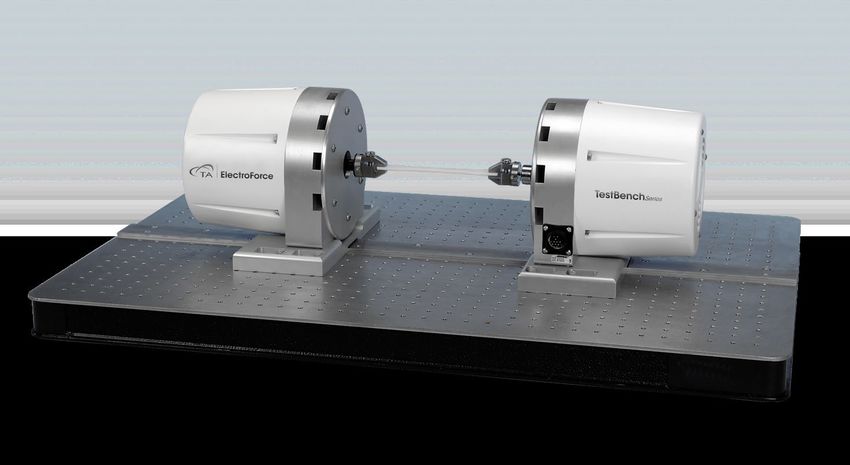
Ideal Setup

        IDEAL PLACEMENT AND BENCH MEASUREMENTS
Select a location with adequate floor and ceiling space and a rigid laboratory bench that is
level and is in a vibration-free environment. Bench must be rated to support several
hundred pounds.

                                                             Distance from the wall:
                                                             0.15 m (0.5 ft) min.

                                                             Table width: 2 m (6 ft)

                                                             Table depth: 1.2 m (4 ft)

    Revision A Issued June 2021                         Page 3
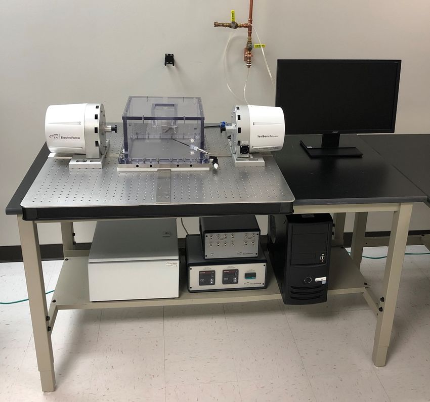
System Components

          MAIN SYSTEM COMPONENTS

                                                            C

 B

                                                                D

     A

                                F             E

A.       Power Supply (Axial)       E.   PCI Box
B.       Test Bench Instrument      F.   Heater Controller (Optional)
C.       Computer Monitor
D.       Computer Tower

     Revision A Issued June 2021                   Page 4
Instrument Measurements
LM1 TESTBENCH – REACTION BASE DIMENSIONS
Height: 51 mm (2 in)
Width: 914 mm (36 in)
Depth: 609 mm (24 in)
Weight: 54 kg (120 lbs)
WITHOUT motor
Weight varies per hardware
configuration and system
options
POWER SUPPLY
Height: 230 mm (9 in)
Width: 405 mm (16 in)
Depth: 510 mm (20 in)
Weight: 27 kg (60 lbs)
Revision A Issued June 2021 Page 5Utility Requirements
POWER
Item Requirement
• 104–132V, 50/60 Hz, 15A
• 207–250V 50/60 Hz, 10A
Instrument Power
• Neutral to Ground (NG) voltage max 0.5 volt
• Safety ground per local regulation
• 104–120V, 50/60 Hz Hz, 10A
PCI-42, 80, 84 Box Power
• 207–230V, 50/60 Hz Hz, 6.3A
• 104–120V, 50/60 Hz, 1A
Power Supply (Optional)
• 207–230V, 50/60 Hz Hz, 0.5A
• 5-15 plug for 120V systems
• 6-20P plug for 230V systems
• International: Line power cord provided is based
Power cords provided on country
5-15 6-15P
Use power cords with plugs appropriate for your circuit.
Supply voltages lower than indicated may result in a degradation of performance.
Ensure that the mains assigned do not also supply power to noise generating equipment
nearby, such as motors, welders, transformers, etc.
An independent heavy GROUND wire must be provided through the power hookup.
Improper grounding may cause severe damage for which the supplier will not accept
responsibility. All power strips must be fully grounded and carry the ground through to
the sockets into which the computer is plugged.
Revision A Issued June 2021 Page 6Utility Requirements
FLUID (FOR BATH)
Item Requirement
Fluid DI water or PBS
Revision A Issued June 2021 Page 7Site Preparation Checklist
ElectroForce® TestBench Series
Enough bench space for instrument and computer
Table width: 2 m (6 ft)
Table depth: 1.2 m (4 ft)
Instrument power is
104–132V, 50/60 Hz, 15A
207–250V 50/60 Hz, 10A
The Customer assumes responsibility for any damage that occurs when the instrument is
moved by someone other than a trained TA Instruments Service Representative.
I hereby acknowledge that all utility requirements have been met per the checklist above and that they
will be ready at the agreed time of installation.
If all utility requirements are not met at the agreed time of installation, additional charges may be
incurred for a return Service trip.
Customer DD MM YYYY
Company City State Country
Please send a signed copy of the completed checklist to your local Service representative.
Revision A Issued June 2021 Page 8TA Instruments Offices
For information on our latest products, contact information, and more, see our website at:
http://www.tainstruments.com.
To find your local TA Instruments office and contact information, visit
http://www.tainstruments.com/contact/ta-directory/
TA Instruments – Waters LLC
Corporate Headquarters
159 Lukens Drive
New Castle, DE 19720
USA
Telephone: 302-427-4000
Fax: 302-427-4001
Email: info@tainstruments.com
Revision A Issued June 2021 Page 9You can also read