EcoMesh Precooling System - Reduce risk of HVAC failure during hot weather - SBH Solutions
←
→
Page content transcription
If your browser does not render page correctly, please read the page content below

EcoMesh Precooling System
                     Reduce risk of HVAC failure during hot weather

1 HVAC normal operating conditions
2 Hot weather events cause HVAC failures
3 HVAC industry response
4 Improve coil operating conditions
5 EcoMesh Precooling System
6 EcoMesh Case Studies
7 Planning an EcoMesh installation
8 Additional inner mesh for Transverse coils
9 Maintenance Requirements

                                                 1
                                                                      SBH SOLUTIONS
1 HVAC normal operating conditions
Air cooled condensers remove the heat from inside the building and reject it to the outdoors.

Chillers and refrigeration units operate best when:

• Sized correctly for the building load
• Air handling is optimised for the occupants
• Installed to the manufacturer's specs
• Have adequate exhaust air clearance
• Operate in the design conditions (ambient
  temperature rarely goes above 40°C)
• Expected life cycle is up to 20 years

                                                               HVAC systems are designed to provide cooling
                                                               capacity for normal operating conditions.

                                                               When sized correctly, HVAC systems perform
                                                               well in all weather conditions.

                                                           2
                                                                                                SBH SOLUTIONS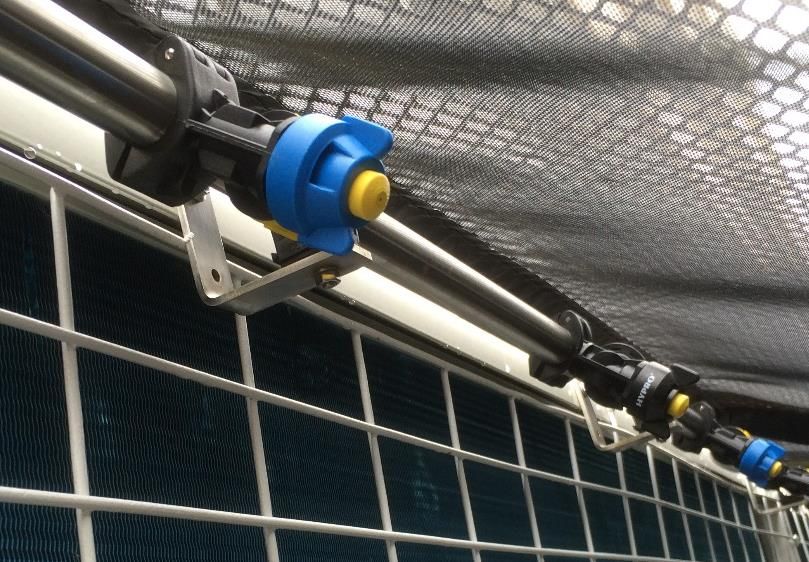
1 HVAC normal operating conditions
Typical example for a Carrier 30GK245 12 fan chiller with 725 kW nominal cooling capacity.           Carrier 30GK245 12 fan chiller with
                                                                                                     nominal capacity 725 kW cooling,

      Chiller pumps chilled water into
      building … LWT (Leaving Water
      Temperature) set at a nominal 7 °C

                                                                                         Carrier 30GK245 - with 12 fans

                                                             3
                                                                                                   SBH SOLUTIONS
1 HVAC normal operating conditions
  Typical cooling capacities - table

LWT - leaving water
temperature at a
nominal setting of 7 °C

                                       •   Nominal capacity 725 kW cooling
                                       •   Compressor input power 279 kW     Each 5 degree rise in ambient
                                       •   Unit input power 313 kW           temperature reduces cooling capacity
                                                                             and increases power demand.

                                                   4
                                                                                        SBH SOLUTIONS
1 HVAC normal operating conditions
Typical cooling capacities - graphed

For operating range between 30 °C and 45 °C:           kW

Cooling capacity reduces … 773 to 629 kW (-19%)
                                                                                                  Cooling
Compressor load increases … 265 to 304 kW (+15%)                                                  Capacity

COP reduces … 2.92 to 2.07 (-29%)

Each degree rise in ambient temperature reduces
cooling capacity and increases power demand.                                                      Compressor
                                                                                                  Input power
                                                                                                   At 43C
                                                                            At 33C   At 36C At 40C 299 kW
                                                                   At 30C   273kW    282kW 292 kW
                                                            At 27C 265kW
                                                            256kW

   HVAC problems are revealed when
   building load exceeds cooling capacity
   - usually during a hot weather event!!

                                                                             Air-on condenser

                                                   5
                                                                                     SBH SOLUTIONS
2 Hot weather events cause HVAC failures
Every summer, hot weather event cause HVAC failure and expensive consequences!

       Deserted shops                         Unproductive                         Prison cell evacuation
                                              staff

Hospital evacuation

                                                                                 And power bill shock
                                Data centre shutdown

                                                         6
                                                                                         SBH SOLUTIONS
2 Hot weather events cause HVAC failures
Most Australian cities experience hot weather events of 35°C or over … summer is the HVAC industry’s busiest season!!

Canberra - maximum temperature days   18                         Maitland - maximum temperature days           32
            30-34    35-40    40+ "hot days"                                  30-34   35-40     40+        "hot days"
  Nov-16      6        0        0     0                            Nov-16       8       4        0             4
  Dec-16     16        0        0     0                             Dec-16     12       6        1             7
   Jan-17    13       12        0     12                            Jan-17      6       6        6             12
  Feb-17      8        4        2     6                             Feb-17     10       4        5             9

Sydney - maximum temperature days                  22            Melbourne - maximum temperature days 9
           30-34    35-40     40+              "hot days"                   30-34   35-39     40+ "hot days"
  Nov-16     4        3        0                   3              Nov-16      2       1        0      1
  Dec-16     9        4        0                   4               Dec-16     7       1        0      1
   Jan-17    5        8        3                   11              Jan-17     4       4        0      4
  Feb-17     6        1        3                   4               Feb-17     4       3        0      3

Dubbo - maximum temperature days                   49            Wagga - maximum temperature days              28
           30-34   35-40      40+              "hot days"                    30-34   35-40     40+         "hot days"
  Nov-16    14       2         0                   2               Nov-16      9       1        0              1
  Dec-16    15      12         0                   12              Dec-16     19       4        0              4
  Jan-17    11      13         6                   19               Jan-17    11      13        3              16
  Feb-17     9       8         8                   16              Feb-17     13       5        2              7

                      Source: BOM data for 2016/17

                                                            7
                                                                                               SBH SOLUTIONS
2 Hot weather events cause HVAC failures
 Main reasons for HVAC failure:
                                                                                              Building load creep - the condensers
 Incorrectly configured HVAC plant             Older HVAC plant - condenser can’t             no longer sized correctly for the load
                                               cope and trip out above 35 C

Hot roof scenario - the roof top is actually     Post installation building modifications        Peak power demand may cause load
5-10C hotter than the design condition           - recirculating air reduces heat rejection      shedding of individual units

                                                                         8
                                                                                                                  SBH SOLUTIONS
3 HVAC industry response
Option 1: Emergency call out by           Option 2: HVAC Optimisation to    Option 3: Replace the units half way
technicians to reset the system …         improve HVAC performance:         through their service life …
                                          eg
                                          •   Start - Stop programming
                                          •   Space temp. setpoints
                                          •   Master air handling
                                          •   Staging of compressors
                                          •   Coil cleaning etc

 But if the system is unmodified, the                                        An expensive and inconvenient scenario!
 next hot weather event will require
 additional call outs … sometimes
 multiple times in day or even weeks

                                          But if condensers cannot reject
                                          sufficient heat, then any
                                          adjustments would be futile.

                                  A less common approach is Option 4 . . . improve the
                                  operating conditions of the condenser coils!!

                                                                  9
                                                                                              SBH SOLUTIONS
4 Improve coil operating conditions
                                                         Referring to the cooling capacities chart …
30-50% of a building’s electricity demand is for
                                                         A simple method to improve efficiency is to
refrigeration or air conditioning.
                                                         improve coil operating conditions by lowering
                                                         the air-on coil temperature …

                                                         Give the coils a “cool change” during hot
                                                         weather events!!

  Efficiency gains in the HVAC system will reduce
  the building’s energy cost … especially during
  hot weather events.

   Pre-cooling alters the micro-climate outside
   the chiller, to lighten the compressor load
   and reduce running costs.                             A lower air-on temperature, increases cooling
                                                         capacity and reduces input power ...

                                                    10
                                                                                   SBH SOLUTIONS
4 Improve coil operating conditions
Pre-cooling the air on coils flattens the
performance curves during hot weather.
kW
The unit operates in an environment where the
temperature never rises above 35C. Cooling
Capacity
Overall effect is to lighten the refrigeration cycle increases
and prolong the life of the HVAC plant.
Typical performance
curves with precooling.
Compressor
Input power
decreases
Air-on condenser
11
SBH SOLUTIONS4 Improve coil operating conditions PAD SYSTEMS
Use a lot of water to achieve 75%
Some common methods for cooling the coil efficiency. A 20 fan chiller will consume
2700 litres per hour.
FOGGING SYSTEMS DIRECT SPRAYING
The mist is effective, but Coil is constantly soaked by a
many nozzles are required. manual operated sprayers.
Also … air is dragged through pads for
the 330 days of the year cooling is not
required.
But direct spraying increases
risk of coil corrosion
Note: Fogging requires high
pressure pumps with fine nozzles
to atomize the spray - prone to
blockages and fouling And pads deteriorate over time and
require periodic replacement
12
SBH SOLUTIONS4 Improve coil operating conditions EcoMesh uses less water to achieve 25
to 45% efficiency. A 20 fan chiller will
Another option is EcoMesh … introduced into Australia in 2014 consume 700-900 litres per hour.
but over 20 years use in Europe, India and the Middle East!
Main advantage of a mesh system compared to other sprayer systems -
the mesh traps most of the water and is only sprayed for a few seconds.
Other advantages:
• Air flows freely through and around the mesh panel.
• No media to replace as poly mesh has a 10 year life
• No additional flashing required to prevent “bypass” air.
• Water consumption is 25- 35% of a similar pad system
EcoMesh uses coarse
sprayers and runs on mains • No additional tanks or water treatment is required.
water pressure. Mesh panels are resprayed
every 30 seconds to maintain
evaporative cooling
13
SBH SOLUTIONS5 EcoMesh Precooling System
EcoMesh is a primary adiabatic solution for Heatcraft and Trane in Europe
Heatcraft Europe:
Adiabatic solution by EcoMesh - panels and sprayers
Trane Europe:
Adiabatic solution by EcoMesh kits and controller
Source: www.ecomesh.eu
14
SBH SOLUTIONS5 EcoMesh Precooling System
EcoMesh precooling process
Mesh panels are installed outside the Water sprayers wet the inside of the Water evaporates off the mesh to
condenser coils. mesh for a few seconds every 30 secs cool the incoming air.
Mesh panels also protect the coil from
Air flows freely through and around “Adiabatic cooling” improves system COP
solar radiation, hail stones and other air
the mesh panels. and minimises risk of head pressure trips
borne debris
in summer.
EcoMesh has a patented
coarse outer net (for Temperatures above 30C For most of the year, mesh in
structural support) and a occur for only a short time front of coils has a negligible
fine inner mesh (for during summer months. impact on the chiller fan load.
capturing water drops).
15
SBH SOLUTIONS5 EcoMesh Precooling System
Factors affecting mesh efficiency:
Estimated cooling efficiency
➢ Ambient temperature and relative humidity
➢ Coil design (standard vertical coil, V coil, W coil, Transverse V
Mesh cooling occurs when water evaporates outside the coil. ➢ Placement of wetted mesh outside coils
➢ Spraying cycle and volume of water used
Mesh efficiency is based on the Delta-T or wet bulb depression
on the day - the dryer the air, the greater the temp drop.
Sites in hotter and dryer cities will run mesh more often and achieve
Best results are achieved when maximum wetted mesh is placed the greatest benefit. For example, Adelaide experienced 25 hot days
in the air stream entering the coils. over 35 C.
Water use is minimal - sprayers increase spray time with each For a mesh efficiency of 33%, see below estimated cooling for an
temperature increment. Adelaide summer (Source: BOM data for Adelaide Kent Town)
Adelaide Kent Town
Mesh cooling efficiency can vary from 25-50% of the Delta-T.
Days Avg Delta T Mesh Days Avg Delta T Mesh
35-39 RH at 37 C effect 40+ RH at 42 C effect
Nov-16 2 15% 18 C 6C 0 N/A N/A N/A
Dec-16 5 16% 18 C 6C 1 15% 20 C 7C
Jan-17 6 21% 16 C 5C 2 12% 21 C 7C
Feb-17 2 14% 18 C 6C 3 30% 15 C 5C
Water drops on inner Mar-17 4 19% 16 C 5C 0 N/A N/A N/A
mesh change state to
vapour and cool air by
latent heat of Estimated mesh cooling across all coils:
evaporation
At 30 C (RH 40%) approx. 1 - 3 °C
At 35 C (RH 30%) approx. 2 - 5 °C
At 40 C (RH 20%) approx. 4 - 7 °C
At 45 C (RH 15%) approx. 6 - 10 °C
16
SBH SOLUTIONS5 EcoMesh Precooling System Emicon RAE
Trane ECGAM
Ballarat Hospital
Data Centre Adelaide
Australian sites since 2014
York YVAA York YLCA
Fujitsu Sydney Queen Elizabeth Hospital
York YLAA
Port Pirie Hospital
Temperzone OPA410
City X Adelaide
Carrier Aquasnap
Netley Police Station Carrier 30RB
Adelaide C Space building St Kilda Town Hall, Melbourne
Canberra
17
SBH SOLUTIONS6 EcoMesh Case Studies
Case study 1: Small packaged unit, Temperzone OPA410 EcoMesh solution: Ambient check 4.04PM: 43.2 °C
Single panel across coil
Temperzone unit was
located on City X arcade
roof in Adelaide city
and regularly tripped
out at 35 C.
The refrigeration service company installed EcoMesh and
although a less efficient solution, EcoMesh prevented further
nuisance trips. Result: Mesh cooling down to 34.7 °C at 4.06 PM
Estimated cooling efficiency:
➢ BOM data at 3PM was 41.2 °C & RH of 24%
➢ Ambient on roof was 43.2 °C and with 24% RH, this implies
a Delta T of 17.4 °C
➢ Central mesh cooled from 43.2 to 34.7 °C or approx. 8.5 °C.
➢ Allowing for 30% losses at mesh open ends, average
cooling across the entire coil is around 5 °C
➢ Estimated cooling efficiency for this site is approx. 29%.
18
SBH SOLUTIONS6 EcoMesh Case Studies
Case study 1: Video of typical cooling
19
SBH SOLUTIONS6 EcoMesh Case Studies
Case study 2: Medium chiller, Emicon 8 fan
EcoMesh solution:
4 x EcoMesh panels
across front and rear of
chiller cabinet
Four water headers,
each with quad
sprayers wet the
inside of the mesh
Two chillers located in a Pooraka data centre.
Hot weather events necessitated direct spraying
of the coils to prevent unit failure.
Direct spraying can damage the coils so an
engineered solution was required.
EcoMesh was installed in early 2016.
20
SBH SOLUTIONS6 EcoMesh Case Studies
Case Study 2, Test 1: Temperature probe to measure cooling at the outer coils (Mar 1st 2016)
The ambient temperature was recorded as 32.2 C at 3:17 PM. The sprayers were activated to wet the mesh for a few seconds, then
probe readings were recorded as an MP4 file. Screen shots from the video below show cooling progress.
0:08 Ambient 32.2 0:16 Sprayers activated (3 sec spray) 0:25 Probe positioned near coils 32.1C
0:43 Temp of 29.3 (2.9 C cooler) 1:13 Temp of 28.9 - mesh still cooling
Ambient conditions on the day
just before next spray cycle at 1:16
➢ BOM data at 3PM was 32.2 °C & RH of 18
➢ Ambient on roof was 32.2 °C and with
18% RH, this implies a Delta T of 15 °C
Results:
The mesh on outer edge of coils cooled the
incoming air by about 3 degrees. For a Delta T
of 15C, cooling efficiency at the open ends
was approx. 20%
21
SBH SOLUTIONS6 EcoMesh - Cooling Effectiveness
Case Study 2, Test 1: Typical cooling measured on a 32 C day
22
SBH SOLUTIONS6 EcoMesh Case Studies Temperature logger results:
Case Study 2, Test 2: Use temperature loggers to
Ambient drop due
record cooling at the inner coils (Mar 1st 2016). Start ambient 32.5 C
to humidification
To avoid false “wet bulb” readings, the loggers were
placed inside plastic bottles. Three probes were
used: one for ambient and two for the upper and
lower part of the coil. Upper and lower
coil probes
The sprayers were activated and the probes recorded
temperature over 30 minutes. Max cooling
23.5C
Ambient conditions on the day
➢ BOM data at 3PM was 32.2 °C & RH of 18
➢ Ambient on roof was 32.2 °C and with 18% RH, this implies a Delta T of 15 °C
Results:
The inner coils were cooled by 9 C. For a Delta T of 15 C, cooling efficiency at the
inner coils is around 60%. Allowing for 20% losses around the edge, this suggests a
total cooling efficiency of approx. 45%.
23
SBH SOLUTIONS6 EcoMesh Case Studies
Case Study 2, Test 3: Temperature probe to measure cooling at the coil behind an inner mesh (Mar 17th, 2016)
To avoid false “wet bulb” readings, the probe was placed inside an electrical conduit. Ambient temperature was recorded as 31.2 C
at 4:36 PM. The sprayers were activated to wet the mesh for a few seconds, then readings were taken with the probe and recorded
as an MP4 file. Screen shots from the video show cooling progress.
Probe in conduit At 4:35 PM Ambient 31.2 At 4:36 Air temp dropped to 29C
At 4:37 Air temp is 26.9C At 4:39 Air temp stabilised at 24.3
Ambient conditions on the day
➢ BOM data at 3PM was 34.2 °C & RH of 30
➢ Ambient on roof was 31.2 °C and with
18% RH, this implies a Delta T of 12 °C
Results:
The inner coils were cooled by 6.9 C. For a Delta T
of 12 C, cooling efficiency at the inner coils is
estimated to be 58%. This is similar to the 60%
efficiency results achieved with the temperature
loggers on Mar 1st.
24
SBH SOLUTIONS6 EcoMesh Case Studies
Case Study 2, Test 4: Observe discharge pressure during EcoMesh cycle (Mar 17th, 2016)
Ambient at this time was 31 C (refer to Test 3). The discharge pressure was recorded for a dry mesh then monitored over the spray
cycle. Below are a series of screen shots from the video to show discharge pressure reducing over time.
0:15 Discharge pressure 20.6 Bar 0:29 Sprayers activated (3 sec spray) 0:40 Discharge pressure 19.8 Bar
0:49 Discharge pressure 19.2 Bar 1:01 Discharge pressure 19.2 Bar 1:47 Discharge pressure 19.2 Bar
Results: EcoMesh pre-cooling reduced the discharge pressure from 20.6 to 19.2 Bar
25
SBH SOLUTIONS6 EcoMesh Case Studies
Case Study 2, Test 5: Return to site and observe mesh operating on a 41C day (Jan 17th, 2017).
Follow up tests were done on this site one year after installation.
Ambient temperature at 4.00 PM: Discharge pressure from Test 4 (Mar 2016)
Outer coils at 4.00 PM: 37.1 C at 32 C dry mesh, no pre cooling … 20.6 bar
40.9 C
Discharge pressure Jan 2017 at 41 C with
Inner coils at 4.00 PM: 27.4 C Ambient conditions on the day EcoMesh running … 21 bar!
➢ BOM data at 3PM was 40.0 °C & RH of 9%
➢ Ambient on roof was 40.9°C and with 9% RH,
this implies a Delta T of 21 °C
Results:
The inner coils were cooled by 13.3 C. For a Delta T
of 21 C, cooling efficiency at the inner coils is
estimated to be 63%. This is similar to the 58% and
60% efficiency achieved in the 2016 tests.
Discharge pressure gauge reveals that on a 41 C day,
EcoMesh helps these chillers cruise as if it were a 32 C day!!
26
SBH SOLUTIONS6 EcoMesh Case Studies
Case study 2: Video of typical cooling - outer coils
27
SBH SOLUTIONS6 EcoMesh Case Studies
Case study 3, Test 1: Large chiller with Transverse V coils, York YLAA 6 fans, 1st March 2017
Between inner coils Between inner coils
No pre-cooling 37.4 C at 3.34PM Inner mesh, 31.9 C at 3.54 PM
With mesh, air-on 33.4 C at 3.44 PM
Ambient conditions on the day
➢ BOM data at 3PM was 37.9 °C & RH of 15%
➢ Ambient was 37.4°C and with 15% RH, this implies a Delta T of 18 °C
Results:
The mesh cooled the incoming air into the coil from 37.4 C to 33.4 C or by
about 4 degrees. On a York, the control panel coil has no cooling so only 5
of the 6 coils are cooled. Allowing for averaging, the entire chiller would
see around 3 degrees and this corresponds to an efficiency of around 17%.
28
SBH SOLUTIONS7 Planning an EcoMesh installation
7.1 Mesh frame coverage
Mesh frame profile -
Mesh is supplied as 1000 or 1200 mm wide panels that are installed along the Short mesh
front side, rear side and optional end to maximise coil coverage.
Tek screw
bracket to top
of top rail
Mesh frame top
Water Mesh apex:
brackets Tek screwed
header 400 mm
to cabinet top rail
Coil
cabinet
1130
Mesh frame bottom
brackets Tek screwed Over spray
wets lower
to cabinet bottom rail mesh
Tek screw bracket
to front of bottom
rail
29
SBH SOLUTIONS7 Planning an EcoMesh installation cont.
7.2 Power and water schematic (supply is customer responsibility)
Chiller “Running” contact:
• Sprayers should only operate when the condenser fans
are running.
• For large chillers with independent condenser systems,
each system should be served by separate water
header/solenoid circuits.
• If so, then additional “Running” contacts will be required.
30
SBH SOLUTIONS7 Planning an EcoMesh installation cont.
7.3 Water schematic (supply is customer responsibility)
Solenoid valve Pressure Water Ball
with drain reducing filters Valve
Speedfit
valve Isolator
connectors
2-3 bar
Mesh 4 Mesh 3 Mesh 2 Mesh 1 Mains
water
Connecting Main supply
Mesh gaps approx. 0-60 mm pipework is pipework is
15mm copper 20mm copper
End stops
Control panel
Chiller cabinet
Water filtration:
• For capital cities, we recommend
Water headers
standard water filters to reduce
(22mm aluminium pipe)
salt content
• For regional areas, we supply
KDF filters
Mesh 4 Mesh 3 Mesh 2 Mesh 1
Optional End
Meshes 5&6
Note: EcoMesh recommends up to 6-8 headers per solenoid
valve to ensure consistent sprayer pressure at 2-3 bar.
31
SBH SOLUTIONS7 Planning an EcoMesh installation cont.
7.4 Water consumption
Each header has 3 x Fulco Tip “Full Cone” sprayers
• Blue nozzle with a yellow tip
• Yellow pressure relief diaphragm
WATER CONSUMPTION GUIDE:
EcoMesh sprays every 30 secs. With a 2 bar water supply, each
water header (triple sprayer) uses 3 x 0.0175 = 0.07 litres/sec.
EcoMesh example: YLCA 4 fan chiller in a 3600 mm long cabinet
Fulco “yellow” tip nozzle flow rates:
Solution: 3 short meshes per side -- total of 6 meshes and 6
water headers. Standard spray cycle of 2 to 5 seconds.
1 bar – 0.74 l/min (0.0123 l/s)
2 bar – 1.05 l/min (0.0175 l/s) 6 water headers will consume 6 x 0.07 = 0.42 litres per second.
3 bar – 1.29 l/min (0.0215 l/s)
4 bar – 1.49 l/min (0.0248 l/s) At 30 deg C, system sprays 4 secs per min using 101 litres/hr
5 bar – 1.66 l/min (0.0277 l/s)
At 45 deg C, system sprays 10 secs per min using 252 litres/hr
32
SBH SOLUTIONS8 Additional inner mesh for Transverse coils
Typical air flow into V side openings
Top of cavity (low volume): 5 m/s
Upper (low volume): 7 m/s
Middle (most volume): 5 m/s
Bottom of cavity (low volume): 2 m/s
Sub cabinet (low volume): 1 m/s
Sub cabinet (low volume):9 Maintenance Requirements
Check area around mesh for Check mesh frame for loose brackets and Mesh will have dirt or scale
excessive water – evidence of tighten bolts if required. deposits over time. Hose down
a faulty sensor, connector or periodically to keep clean.
solenoid.
Check water spray for “cone-
Check controller digital shaped” spray pattern and 90
display – should be display degree alignment towards
correct ambient temperature mesh.
reading
Mesh can be unhooked and
flipped up to access for
Check water pipes and cleaning
connectors for leaks.
Turn system off during winter by isolating electrics and draining the pipes.
34
SBH SOLUTIONSEcoMesh – Adiabatic Cooling System
EcoMESH
Supplied by:
SBH Solutions
3 Ballantyne Street
Magill SA 5072
P: 08 7122 1114
E: info@sbhsolutions.com.au
35
SBH SOLUTIONSYou can also read