DUMBWAITER WINCH Models: RF300 - RF500 - RF800 - Use and maintenance manual - Tecno3 srl Lavorazioni Meccaniche
←
→
Page content transcription
If your browser does not render page correctly, please read the page content below
Use and maintenance manual

              DUMBWAITER WINCH
          Models: RF300 – RF500 – RF800

 Tecno3 srl Lavorazioni Meccaniche
 Via dei Marmorari n. 62 41057 Spilamberto (Mo) Italy
 Tel: +39 059781609 E-mail: info@tecno3srl.net web: www.tecno3srl.net

10/2020                                 Page 1                          rev.00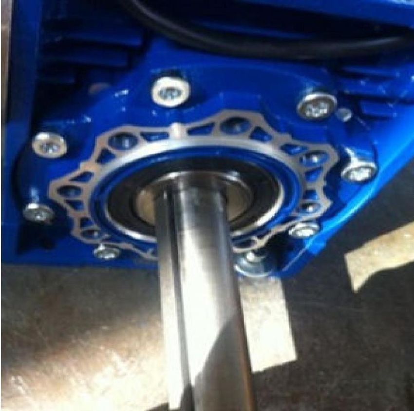
Note: the descriptions and the pictures provided in the present
 manual are not binding; Tecno3 srl Lavorazioni Meccaniche reserves
 the right to modify them as necessary at any time and without prior
 notice.

                              Terminal box

                                                 Pulley

                                                      Brake level

    Flywheel

               Engine

                                                      Brake
                           Gearbox

10/2020                                                       Page. 2
                              rev.00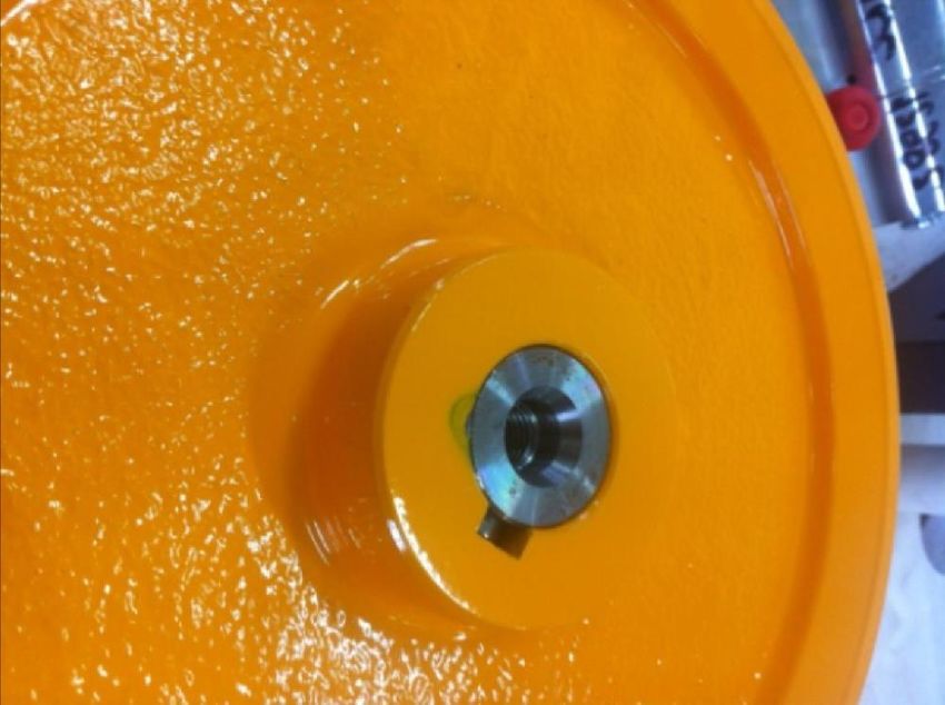
Electrical connections
In the standard execution the parking disk brake is powered by
220/240 V DC.
The 3-phase asynchronous electric motor is powered by 380/400 V AC
at 50 Hz o 60 Hz (depending on the model).

10/2020                                                     Page. 3
                             rev.00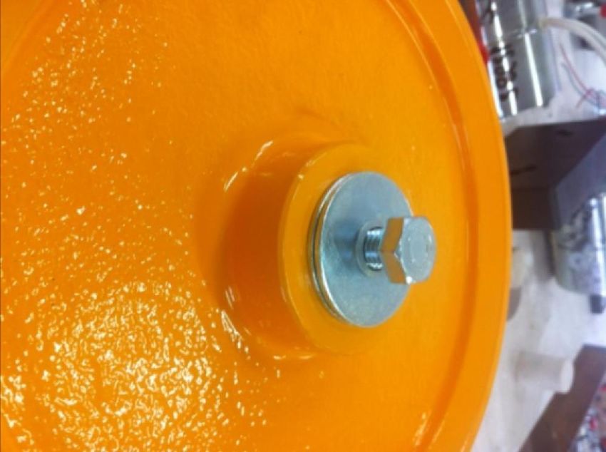
Hand operation of the brake in case of

emergency
                                                                            B

 – AUTHORIZED PERSONNEL
       ONLY –
     Perform the following                A
    operations in the given
    order:
  1) Turn off the main switch in
     the equipment room.
  2) Firmly hold the crankshaft
     using the
     flywheel (A)
  3) Apply the brake level (B);
     the crankshaft must turn freely. Move the crankshaft (A) in the most
     suitable direction until the cab reaches the required position, i.e. until it
     lines up with the reference mark on the steel ropes (if any).
  4) Release the brake lever (B).

 ATTENTION: springs must be always under load; never release them in order
 to facilitate the manual handling.

Lubrification
The winch models RF300, RF500 and RF800 are equipped with permanent
lubrification.

10/2020                                                                         Page. 4
                                     rev.00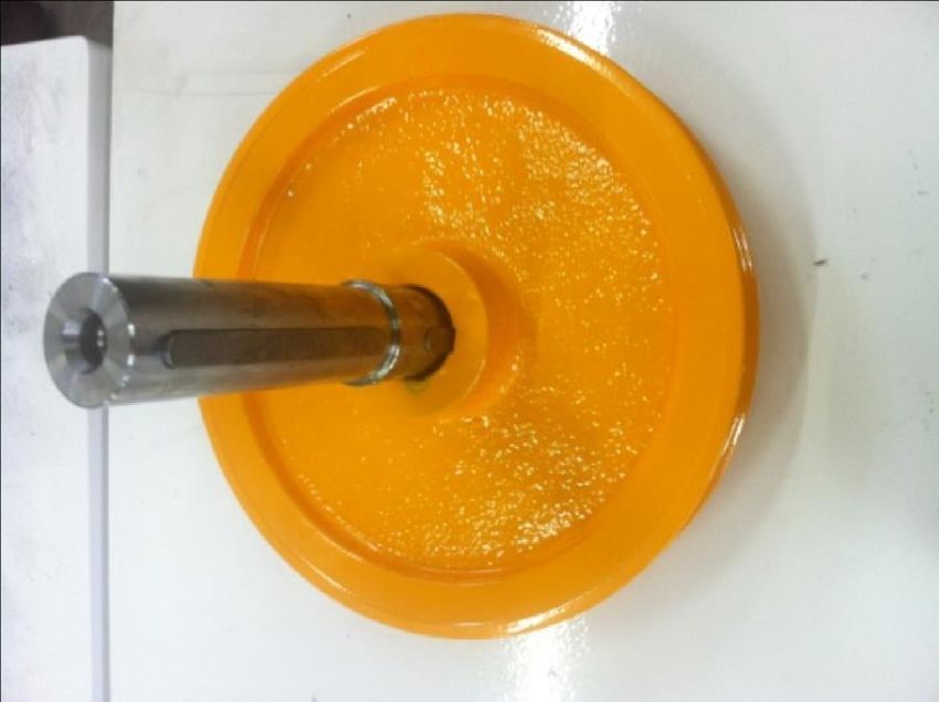
Braking adjustment
The adjustment requires that
the installation is not fixed with             6                  3
ropes. If the installation is shut
down and the solenoid is de-
energized, loose the two bolts        2
                                                                         x
(1) and slightly unscrew the
screws (4) (4x, see picture)
that fix the coil body (2) to the
brake body (3).
Screw or unscrew the screws
(5) (4x, see picture) in order to
increase or decrease the stroke
and obtain the required braking
force. Use a feeler gauge to
measure the distance (4
measuring points at least)
between the flat face of the
brake body (3) and the coil
body (2).
The solenoid has a default
stroke of 0,5 mm.
Tighten the screws (4) and
screw the bolts (1) until they
line up with the lever (with
                                     5              1
little clearance).
Correct the pre-load of the                                   4
springs in the coil body as
appropriate, in order to adjust the braking intensity. Adjust the screws (6) (4x)
to increase or decrease the compression of the springs, in order to get the
required braking force.
The material of the brake disc can wear out over time, especially in case of
wrong adjustment. This can result in a less effective braking performance due
to the reduction of the pre-load of the springs.
It is strongly recommended that you follow the whole above-mentioned
adjustment procedure (the pre-load adjustment of the springs is not enough).

10/2020                                                                    Page. 5
                                     rev.00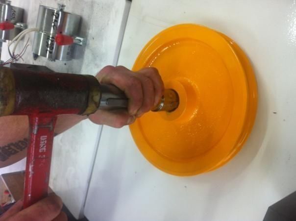
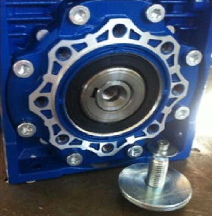
Instructions for changing the position/direction

    1. Unscrew the bolt of the turning shaft

    2. Remove the turning shaft

10/2020                                        Page. 6
                                    rev.00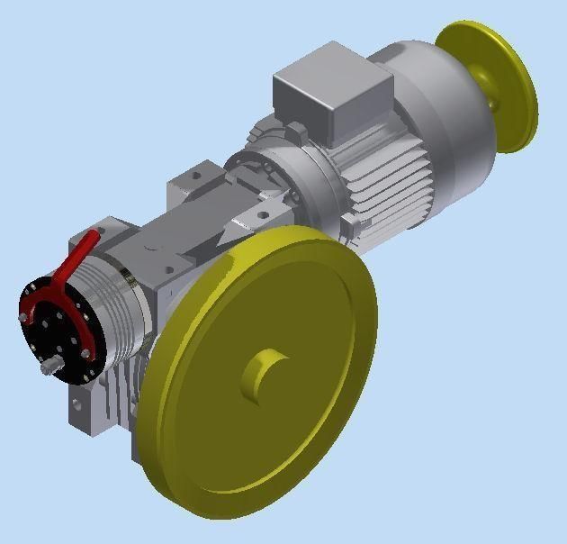
3. Insert the turning shaft on the required side and tighten the previously
       removed bolt

10/2020                                                                   Page. 7
                                    rev.00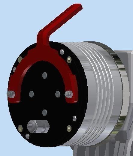
Pulley assembly
   1. Disassemble the turning shaft following the previous
      procedure

   2. Insert the conical part of the shaft into the pulley
   3. Tap gently with a soft-faced hammer

10/2020                                                      Page. 8
                                     rev.00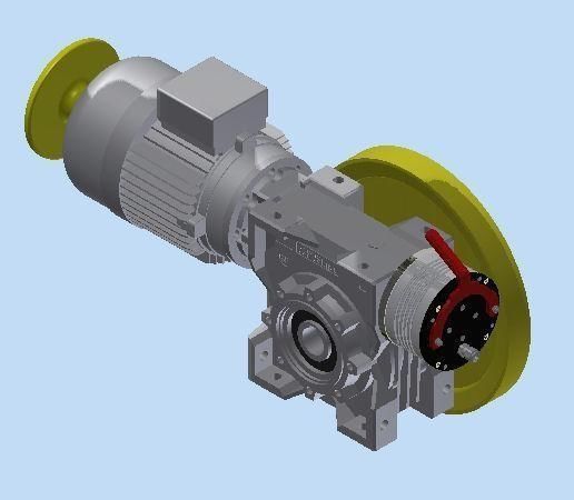
4. Fix the bolt as shown in the picture

   5. Re-insert the shaft with the pulley into the gearbox, on the required side

10/2020                                                                   Page. 9
                                    rev.00
Warnings
Replacement parts are available; please provide Tecno3 srl Lavorazioni
Meccaniche with the following information:
1) winch model
2) serial number S/N (you can find it on the label plate of the winch)
Declaration of conformity
• Dichiarazione conforme all’Allegato II-B, ai sensi della “Direttiva Macchina”
2006/42/CE e successive modificazioni.
“La Tecno3 srl Lavorazioni Meccaniche, situata in Via dei Marmorari n.62 41057
Spilamberto (Mo) Italia, è costruttrice dell’argano destinato esclusivamente all’impiego
in montavivande/montacarichi non destinato al trasporto di persone, cui si
accompagna la seguente dichiarazione:
i prodotti, essendo destinati ad essere incorporati in un insieme complesso, non
possono essere messi in servizio finché tutto l’insieme complesso non sia stato
dichiarato conforme”.
• EC Declaration of conformity in accordance with Machinery Directive
2006/42/EC, Annex II (including later amendments)
“Tecno3 srl Lavorazioni Meccaniche, located in Via dei Marmorari n. 62 41057
Spilamberto (Mo) Italy, is the manufacturer of the above mentioned gear that is intended
exclusively for the use in dumbwaiters and is non designed to transport people. The
winch is accompanied by the following declaration:
as the product is part of an assembly, it must not be put into service until the final
machinery into which it is to be incorporated has been declared in conformity with the
provisions of the Machinery Directive”.
Property
This document and the gear it describes are exclusively owned by Tecno3 srl Lavorazioni
Meccaniche
10/2020 Page. 10
rev.00You can also read