DOD ENTERPRISE DEVSECOPS REFERENCE DESIGN: CNCF KUBERNETES MARCH 2021 VERSION 2.0
←
→
Page content transcription
If your browser does not render page correctly, please read the page content below
Unclassified

                                   UNCLASSIFIED

DoD Enterprise
DevSecOps Reference
Design:
CNCF Kubernetes

March 2021

Version 2.0

  DISTRIBUTION STATEMENT A. Approved for public release. Distribution is unlimited.

                                  UNCLASSIFIED
                                    Unclassified                                      1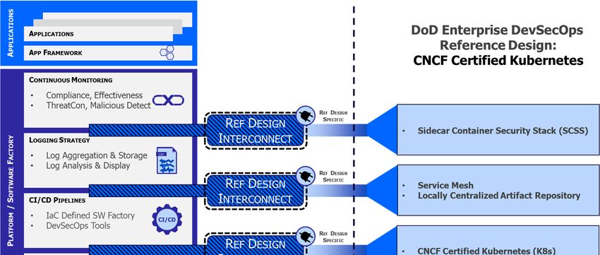
UNCLASSIFIED

Document Set Reference

                         UNCLASSIFIED   2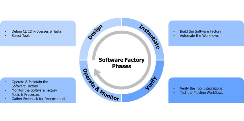
UNCLASSIFIED

Document Approvals

Approved by:

CHAILLAN.NICOL Digitally    signed by
                    CHAILLAN.NICOLAS.MAXIME.
AS.MAXIME.1535 1535056524
                    Date: 2021.05.04 10:28:37
056524
________________________________________
                    -04'00'

Nicolas Chaillan
Chief Software Officer, Department of Defense, United States Air Force, SAF/AQ

                                     UNCLASSIFIED                                3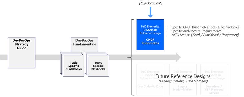
UNCLASSIFIED

Trademark Information
Names, products, and services referenced within this document may be the trade names,
trademarks, or service marks of their respective owners. References to commercial vendors and
their products or services are provided strictly as a convenience to our readers, and do not
constitute or imply endorsement by the Department of any non-Federal entity, event, product,
service, or enterprise.

                                      UNCLASSIFIED                                         4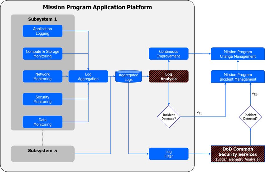
UNCLASSIFIED

Contents
1    Introduction .......................................................................................................................... 7
    1.1    Background................................................................................................................... 7
    1.2    Purpose .......................................................................................................................... 7
    1.3    DevSecOps Compatibility ......................................................................................... 8
    1.4    Scope .............................................................................................................................. 8
    1.5    Document Overview ................................................................................................... 9
    1.6    What’s New in Version 2............................................................................................ 9
2    Assumptions and Principles ......................................................................................... 10
3    Software Factory Interconnects ................................................................................... 10
    3.1    Cloud Native Access Points ................................................................................... 11
    3.2    CNCF Certified Kubernetes .................................................................................... 11
    3.3    Locally Centralized Artifact Repository .............................................................. 12
    3.4    Sidecar Container Security Stack (SCSS) .......................................................... 13
    3.5    Service Mesh .............................................................................................................. 16
4    Software Factory K8s Reference Design ................................................................... 17
    4.1    Containerized Software Factory ............................................................................ 18
    4.2    Hosting Environment ............................................................................................... 20
    4.3    Container Orchestration .......................................................................................... 20
5    Additional Tools and Activities ..................................................................................... 22
    5.1    Additional Deployment Types................................................................................ 29
     5.1.1        Blue/Green Deployments .................................................................................... 29
     5.1.2        Canary Deployments ........................................................................................... 29
     5.1.3        Rolling Deployments ............................................................................................ 29
     5.1.4        Continuous Deployments .................................................................................... 30
    5.2    Continuous Monitoring in K8s ............................................................................... 30
     5.2.1        CSP Managed Services for Continuous Monitoring ....................................... 31

                                                         UNCLASSIFIED                                                                          5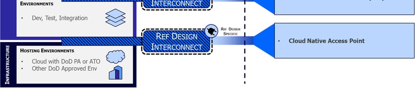
UNCLASSIFIED

Figures
Figure 1: Kubernetes Reference Design Interconnects ............................................................. 11
Figure 2: Container Orchestrator and Notional Nodes ............................................................. 12
Figure 3: Sidecar Container Relationship to Application Container ........................................ 13
Figure 4: Software Factory Implementation Phases.................................................................. 17
Figure 5: Containerized Software Factory Reference Design ................................................... 20
Figure 6: DevSecOps Platform Options ...................................................................................... 21
Figure 7: Software Factory - DevSecOps Services ..................................................................... 22
Figure 8: Logging and Log Analysis Process ............................................................................. 31

Tables
Table 1 Sidecar Security Monitoring Components..................................................................... 15
Table 2: CD/CD Orchestrator Inputs/Outputs............................................................................ 18
Table 3: Security Activities Summary and Cross-Reference...................................................... 23
Table 4: Develop Phase Activities ............................................................................................... 23
Table 5: Build Phase Tools.......................................................................................................... 23
Table 6: Build Phase Activities.................................................................................................... 24
Table 7: Test Phase Tools ............................................................................................................ 24
Table 8: Test Phase Activities ...................................................................................................... 25
Table 9: Release and Deliver Phase Tools .................................................................................. 25
Table 10: Release and Deliver Phase Activities .......................................................................... 25
Table 11: Deploy Phase Tools ..................................................................................................... 26
Table 12: Deploy Phase Activities ............................................................................................... 27
Table 13: Operate Phase Activities.............................................................................................. 27
Table 14: Monitor Phase Tools ................................................................................................... 28
Table 15: CSP Managed Service Monitoring Tools ................................................................... 28

                                                        UNCLASSIFIED                                                                   6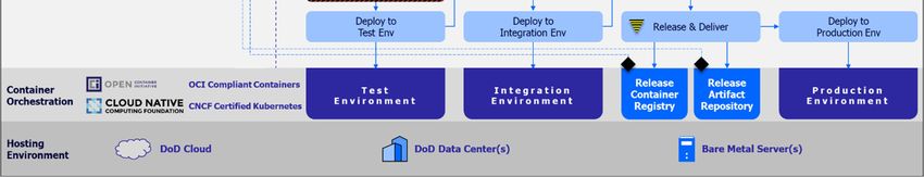
UNCLASSIFIED
1 Introduction
1.1 Background
Modern information systems and weapons platforms are driven by software. As such, the DoD
is working to modernize its software practices to provide the agility to deliver resilient software at
the speed of relevance. DoD Enterprise DevSecOps Reference Designs are expected to
provide clear guidance on how specific collections of technologies come together to form a
secure and effective software factory.
1.2 Purpose
This DoD Enterprise DevSecOps Reference Design is specifically for Cloud Native Computing
Foundation (CNCF) Certified Kubernetes implementations. This enables a Cloud agnostic,
elastic instantiation of a DevSecOps factory anywhere: Cloud, On Premise, Embedded System,
Edge Computing.
For brevity, the use of the term ‘Kubernetes’ or ‘K8s’ throughout the remainder of this
document must be interpreted as a Kubernetes implementation that properly submitted
software conformance testing results to the CNCF for review and corresponding
certification. The CNCF lists over 90 Certified Kubernetes offerings that meet software
conformation expectations. 1
It provides a formal description of the key design components and processes to provide a
repeatable reference design that can be used to instantiate a DoD DevSecOps Software
Factory powered by Kubernetes. This reference design is aligned to the DoD Enterprise
DevSecOps Strategy, and aligns with the baseline nomenclature, tools, and activities defined in
the DevSecOps Fundamentals document and its supporting guidebooks and playbooks.
The target audiences for this document include:
DoD Enterprise DevSecOps capability providers who build DoD Enterprise DevSecOps
hardened containers and provide a DevSecOps hardened container access service.
DoD Enterprise DevSecOps capability providers who build DoD Enterprise DevSecOps
platforms and platform baselines and provide a DevSecOps platform service.
DoD organization DevSecOps teams who manage (instantiate and maintain)
DevSecOps software factories and associated pipelines for its programs.
DoD program application teams who use DevSecOps software factories to develop,
secure, and operate mission applications.
Authorizing Officials (AOs).
This reference design aligns with these reference documents:
1Cloud Native Computing Foundation, “Software conformance (Certified Kubernetes,” [ONLINE] Available:
https://www.cncf.io/certification/software-conformance/. [Accessed 8 February 2021].
UNCLASSIFIED 7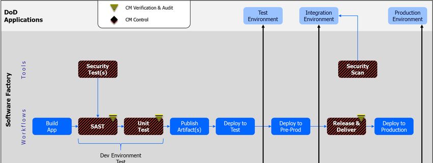
UNCLASSIFIED
DoD Digital Modernization Strategy.2
DoD Cloud Computing Strategy.3
DISA Cloud Computing Security Requirements Guide.4
DISA Secure Cloud Computing Architecture (SCCA).5
Presidential Executive Order on Strengthening the Cybersecurity of Federal Networks
and Critical Infrastructure (Executive Order (EO) 1380).6
National Institute of Standards and Technology (NIST) Cybersecurity Framework.7
NIST Application Container Security Guide.8
Kubernetes (draft) STIG – Ver 1.9
DISA Container Hardening Process Guide, V1R1.10
1.3 DevSecOps Compatibility
This reference design asserts version compatibility with these supporting DevSecOps
documents:
DoD Enterprise DevSecOps Strategy Guide, Version 2.0.
DevSecOps Tools and Activities Guidebook, Version 2.0.
1.4 Scope
This reference design is product-agnostic and provides execution guidance for use by software
teams. It is applicable to developing new capabilities and to sustaining existing capabilities in
both business and weapons systems software, including business transactions, C3, embedded
systems, big data, and Artificial Intelligence (AI).
This document does not address strategy, policy, or acquisition.
2 DoD CIO, DoD Digital Modernization Strategy, Pentagon: Department of Defense, 2019.
3 Department of Defense, "DoD Cloud Computing Strategy," December 2018.
4 DISA, “Department of Defense Cloud Computing Security Requirements Guide, v1r3,” March 6, 2017
5 DISA, "DoD Secure Cloud Computing Architecture (SCCA) Functional Requirements," January 31, 2017.
6 White House, "Presidential Executive Order on Strengthening the Cybersecurity of Federal Networks and Critical
Infrastructure (EO 1380)," May 11, 2017.
7National Institute of Standards and Technology, Framework for Improving Critical Infrastructure Cybersecurity,
2018.
8 NIST, "NIST Special Publication 800-190, Application Container Security Guide," September 2017.
9 DoD Cyber Exchange, “Kubernetes Draft STIG – Ver 1, Rel 0.1,” December 15, 2020.
10 DISA, “Container Hardening Process Guide, V1R1,” October 15, 2020
UNCLASSIFIED 8
UNCLASSIFIED
1.5 Document Overview
The documentation is organized as follows:
Section 1 describes the background, purpose and scope of this document.
Section 2 identifies the assumptions relating to this design.
Section 3 describes the DevSecOps software factory interconnects unique to a
Kubernetes reference design.
Section 4 describes the containerized software factory design.
Section 5 captures the additional required and preferred tools and activities, building
upon the DevSecOps Tools and Activities Guidebook as a baseline.
1.6 What’s New in Version 2
Refactored the document’s overall structure to align with the shift to a DevSecOps
Document Set approach.
UNCLASSIFIED 9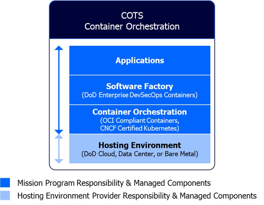
UNCLASSIFIED
2 Assumptions and Principles
This reference design makes the following assumptions:
No specific Kubernetes implementation is assumed, but the selected Kubernetes
implementation must have submitted conformance testing results for review and
certification by the CNCF.
Vendor lock-in is avoided by mandating a Certified Kubernetes implementation;
however, product lock-in into the Kubernetes API and its overall ecosystem is openly
recognized.
It is critically important to avoid the proprietary APIs that are sometimes added
by vendors on top of the existing CNCF Kubernetes APIs. These APIs are not
portable and may create vendor lock-in!
Adoption of hardened containers as a form of immutable infrastructure results in
standardization of common infrastructure components that achieve consistent and
predictable results.
This reference design depends upon a number of DoD Enterprise Services, which will be
named throughout this document.
3 Software Factory Interconnects
The DevSecOps Fundamentals describes a DevSecOps platform as a multi-tenet environment
consisting of three distinct layers: Infrastructure, Platform/Software Factory, and Application(s).
Each reference design is expected to identify its unique set of tools and activities that exist at
the boundaries between the discrete layers, known as Reference Design Interconnects. Well-
defined interconnects in a reference design enable tailoring of the software factory design, while
ensuring that core capabilities of the software factory remain intact.
Figure 1: Kubernetes Reference Design Interconnects identifies the specific Kubernetes
interconnects that must be present in order to be compliant with this reference design. The
specific interconnects include:
Cloud Native Access Point (CNAP) above the Infrastructure layer to manage all north-
south network traffic.
Use of Kubernetes in each of the development environments.
Clear identification of a locally centralized artifact repository to host hardened containers
from Iron Bank, the DoD Centralized Artifact Repository (DCAR) of hardened and
centrally accredited containers.
UNCLASSIFIED 10UNCLASSIFIED
Use of a service mesh within the K8s orchestrator to manage all east-west network
traffic.
Mandatory adoption of the Sidecar Container Security Stack (SCSS) to implement zero
trust down to the container/function level, also providing behavior protection.
Each of these interconnects will be described fully next.
Figure 1: Kubernetes Reference Design Interconnects
3.1 Cloud Native Access Points
A Cloud Native Access Point (CNAP) provides a zero-trust architecture on Cloud One to provide
access to development, testing, and production enclaves at Impact Level 2 (IL-2), Impact Level
4 (IL-4), and Impact Level 5 (IL-5).11 CNAP provides access to Platform One DevSecOps
environments by using an internet-facing Cloud-native zero trust environment. CNAP’s zero
trust architecture facilitates development team collaboration from disparate organizations. (A
CNAP reference design is forthcoming.)
3.2 CNCF Certified Kubernetes
Kubernetes is a container orchestrator that manages the scheduling and execution of Open
Container Initiative (OCI) compliant containers across multiple nodes, depicted in Figure 2. OCI
is an open governance structure for creating open industry standards around both container
11 DISA, “Department of Defense Cloud Computing Security Requirements Guide, v1r3,” Mar 6, 2017
UNCLASSIFIED 11UNCLASSIFIED
formats and runtimes.12 The container is the standard unit of work in this reference design.
Containers enable software production automation in this reference design, and they also allow
operations and security process orchestration.
Figure 2: Container Orchestrator and Notional Nodes
Kubernetes provides an API that ensures total abstraction of orchestration, compute, storage,
networking, and other core services that guarantees software can run in any environment, from
the Cloud to embedded inside of platforms like jets or satellites.
The key benefits of adopting Kubernetes include:
Multimodal Environment: Code runs equally well in a multitude of compute
environments, benefitting from the K8s API abstraction.
Baked-In Security: The Sidecar Container Security Stack is automatically injected into
any K8s cluster with zero trust.
Resiliency: Self-healing of unstable or crashed containers.
Adaptability: Containerized microservices create highly-composable ecosystems.
Automation: Fundamental support for a GitOps model and IaC speed processes and
feedback loops.
Scalability: Application elasticity to appropriately scale and match service demand.
The adoption of K8s and OCI compliant containers are concrete steps towards true
microservice reuse, providing the Department with a compelling ability to pursue higher orders
of code reuse across an array of programs.
3.3 Locally Centralized Artifact Repository
A Locally Centralized Artifact Repository is a local repository tied to the software factory. It
stores artifacts pulled from Iron Bank, the DoD repository of digitally signed binary container
images that have been hardened. The local artifact repository also likely stores locally
developed artifacts used in the DevSecOps processes. Artifacts stored here include, but are not
12 The Linux Foundation Projects, “Open Container Initiative,” [Online] Available at: https://opencontainers.org.
UNCLASSIFIED 12UNCLASSIFIED
limited to, container images, binary executables, virtual machine (VM) images, archives, and
documentation.
The Iron Bank artifact repository provides hardened, secure technical implementation guide
(STIG) compliance, and centrally updated, scanned, and signed containers that increases the
cyber survivability of these software artifacts. At time of writing this reference design, over 300
artifacts were in Iron Bank, with more being added continuously.
Programs may opt for a single artifact repository and rely on the use of tags to distinguish
between the different content types. It is also permissible to have separate artifact repositories
to store local artifacts and released artifacts.
3.4 Sidecar Container Security Stack (SCSS)
The cyber arena is an unforgiving hostile environment where even a minute exposure and
compromise can lead to catastrophic failures and loss of human life. Industry norms now
recognize that a modern holistic cybersecurity posture must include centralized logging and
telemetry, zero trust ingress/egress/east-west network traffic, and behavior detection at a
minimum.
A cybersecurity stack is frequently updated as threat conditions evolve. A key benefit of a
cybersecurity K8s sidecar container design is rapidly deployed updates without any
recompilation or rebuild required of the microservice container itself. To support this approach,
the SCSS is available from the Iron Ban repository as a hardened container that K8s
automatically injects into each container group (pod). This decoupled architecture, shown in
Figure 3, speeds deployment of an updated cyber stack without requiring any type of re-
engineering by development teams.
Figure 3: Sidecar Container Relationship to Application Container
As shown in Figure 3, the sidecar can share state with the application container. In particular,
the two containers can share disk and network resources while their running components are
fully isolated from one another.
UNCLASSIFIED 13UNCLASSIFIED
The complete set of sidecar container security monitoring components are captured in Table 1
on the next page. Capability highlights include:
Centralized logging and telemetry that includes extract, transform, and load (ETL)
capabilities to normalize log data.
Robust east/west network traffic management (whitelisting).
Zero Trust security model.
Whitelisting.
Role-Based Access Control.
Continuous Monitoring.
Signature-based continuous scanning using Common Vulnerabilities and Exposures
(CVEs).
Runtime behavior analysis.
Container policy enforcement.
UNCLASSIFIED 14UNCLASSIFIED
Table 1 Sidecar Security Monitoring Components
Tool Features Benefits Baseline
Logging agent Send logs to a logging service Standardize log collection to a central REQUIRED
location. This can also be used to send
notifications when there is anomalous
behavior.
Logging Storage and Stores logs and allows searching logs Place to store logs REQUIRED
Retrieval Service
Log visualization and Ability to visualize log data in various ways Helps to find anomalous patterns PREFERRED
analysis and perform basic log analysis.
Container policy Support for Security Content Automation Automated policy enforcement REQUIRED
enforcement Protocol (SCAP) and container configuration
policies. These policies can be defined as
needed.
Runtime Defense Creates runtime behavior models, including Dynamic, adaptive cybersecurity REQUIRED
whitelist and least privilege
Service Mesh proxy Ties to the Service Mesh. Used with a Enables use of the service mesh. REQUIRED
microservices architecture.
Service Mesh Used for a microservices architecture Better microservice management. REQUIRED
Vulnerability Provides vulnerability management Makes sure everything is properly patched REQUIRED
Management to avoid known vulnerabilities
CVE Service / Host Provides CVEs. Used by the vulnerability Makes sure the system is aware of known REQUIRED
Based Security management agent in the security sidecar vulnerabilities in components.
container.
Artifact Repository Storage and retrieval for artifacts such as One location to obtain hardened artifacts REQUIRED
containers. such as containers
Zero Trust model Provides strong identities per Pod with Reduces attack surface and improves REQUIRED
down to the certificates, mTLS tunneling and whitelisting baked-in security
container level of East-West traffic down to the Pod level.
UNCLASSIFIED 15UNCLASSIFIED
3.5 Service Mesh
A service mesh enhances cybersecurity by controlling how different parts of an application
interact. It is a dedicated infrastructure layer baked-in to the software application itself; it is not a
“bolt-on” component. Some of the specific capabilities of a service mesh in K8s including
monitoring east-west network traffic, routing traffic based on a declarative network traffic model
that can deny all network traffic by default, and dynamically injecting strong certificate-based
identities without requiring access to the underlying code that built the software container. A
service mesh also typically takes over ownership of the iptables in order to inject an mTLS
tunnel with FIPS compliant cryptographic algorithms to further protect all data in motion.
Service mesh integration into the K8s cluster reduces the cyber-attack surface, and when
coupled with behavior detection, it can proactively kill any container that is drifting outside of its
expected operational norms. These capabilities restrict the ability of a bad actor to laterally
move around within the K8s cluster and fully eliminate the ability of the bad actor to achieve
escalated privileges. For these reasons, service mesh integration is a powerful component in
ensuring the cyber survivability of the software factory and the containerized applications
produced by the factory’s pipelines.
UNCLASSIFIED 16UNCLASSIFIED
4 Software Factory K8s Reference Design
This section will discuss the software factory design required for this reference design. It is
based on the DoD Enterprise DevSecOps Container Service offering to create a software
factory using DevSecOps tools from hardened containers stored in Iron Bank.
All software factory implementations follow the DevSecOps philosophy and go through four
unique phases: Design, Instantiate, Verify, Operate & Monitor. Figure 4 illustrates the phases,
activities, and the relationships with the application lifecycle. Security is applied across all
software factory phases. The SCSS must be used for cybersecurity monitoring of the factory in
this reference design.
Figure 4: Software Factory Implementation Phases
The components of this reference design’s software factory must be instantiated as follows: A
CSP-agnostic solution running a CNCF Certified K8s using hardened containers from Iron Bank.
This design recognizes that K8s is well-suited to act as the engine powering a continuous
integration/continuous delivery (CI/CD) orchestrator, coordinating multiple parallel DevSecOps
pipelines. K8s manages pipeline creation, pipeline modification, overall pipeline execution, and
finally pipeline termination.
The software factory leverages technologies and tools to automate the CI/CD pipeline
processes defined in the DevSecOps lifecycle plan phase. There are no “one size fits all” or
hard rules about what CI/CD processes should look like and what tools must be used. Each
software team needs to embrace the DevSecOps culture and define processes that suit its
software system architectural choices. The tool chain selection is specific to the software
programming language choices, application type, tasks in each software lifecycle phase, and
the system deployment platform.
DevSecOps teams create a pipeline workflow in the CI/CD orchestrator by specifying a set of
stages, stage conditions, stage entrance and exit control rules, and stage activities. The CI/CD
UNCLASSIFIED 17UNCLASSIFIED
orchestrator automates the pipeline workflow by validating the stage control rules. If all the
entrance rules of a stage are met, the orchestrator will transition the pipeline into that stage and
perform the defined activities by coordinating the tools via plugins. If all the exit rules of the
current stage are met, the pipeline exits out the current stage and starts to validate the entrance
rules of the next stage. Table 2 shows the features, benefits, and inputs and outputs of the
CI/CD orchestrator.
Table 2: CD/CD Orchestrator Inputs/Outputs
Tool Features Benefits Inputs Outputs Baseline
CI/CD Create Customizable Human input Pipeline REQUIRED
orchestrator pipeline pipeline about: workflow
workflow solution A set of configuration
stages
A set of
event
triggers
Each stage
entrance and
exit control
gate
Activities in
each stage
Orchestrate Automate the Event triggers Pipeline
pipeline CI/CD tasks; (such as code workflow
workflow Auditable trail commit, test execution
execution of activities results, human results (such
by input, etc.); as control
coordinating Artifacts from the gate
other plugin artifact validation,
tools or repository stage
scripts. transition,
activity
execution,
etc.);
Event and
activity audit
logs
4.1 Containerized Software Factory
Software factory tools include a CI/CD orchestrator, a set of development tools, and a group of
tools that operate in different DevSecOps lifecycle phases. These tools are pluggable and must
integrate into the CI/CD orchestrator. In this reference design, instantiations must rely a
containerized software factory instantiated from a set of DevSecOps hardened
containers accessed directly from Iron Bank. Iron Bank containers are preconfigured and
secured to reduce the certification and accreditation burden and are often available as a
predetermined pattern or pipeline that will need limited or no configuration.
UNCLASSIFIED 18UNCLASSIFIED
Running a CI/CD pipeline is a complex activity. Containerization of the entire CI/CD stack
ensures there is no drift possible between different K8s cluster environments (development,
test, staging, production). It further ensures there is no drift between different K8s cluster
environments spanning multiple classification levels. Containerization also streamlines the
update/accreditation process associated with the introduction and adoption of new DevSecOps
tooling.
Figure 5, illustrates a containerized software factory reference design. The software factory is
built on an underlying container orchestration layer powered by K8s in a host environment. For
clarity, the software factory produces DoD applications and application artifacts as a product.
Applications typically use different sets of hardened containers from the Iron Bank than the ones
used to create the software factory.
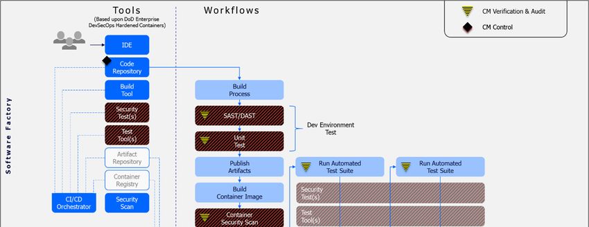
The software factory reference design captured in Figure 5 illustrates how cybersecurity is
weaved into the fabric of each factory pipeline. All of the tooling within the factory is based on
hardened containers pulled from Iron Bank.
Moving from left to right, as code is checked into a branch triggering the CI/CD pipeline
workflow and resulting automated build, SAST, DAST, and unit tests are executed, as the
orchestrator coordinates different tools to perform various tasks defined by the pipeline. If the
build is successful and a container image is defined, a container security scan is triggered.
Some tests and security tasks may require human involvement or consent before being
considered complete and passed. If all of these tests are successful, then the artifact is
deployed into the test environment. If all of the entrance rules of the next stage are met, the
orchestrator will transition the pipeline into that stage and perform the defined activities by
coordinating the tools via plugins. When all stages are complete, a significant number of
security activities have completed and the artifact is eligible for deployment into production.
Deployment into production should be fully automated, but may be gated by a human actually
pressing a button to trigger the deployment.
UNCLASSIFIED 19UNCLASSIFIED
Figure 5: Containerized Software Factory Reference Design
DoD programs may have already implemented a DevSecOps platform. Operating a custom
DevSecOps platform is an expensive endeavor because software factories require the same
level of continuous investment as a software application. There are financial benefits for
programs to plan a migration to a containerized software factory, reaping the benefits of
centrally managed and hardened containers that have been fully vetted. In situations where a
containerized software factory is impractical, or the factory requires extensive policy
customizations, the program should consult with DoD CIO and (if applicable) its own
DevSecOps program office to explore options and collaborate to create, sustain, and deliver
program-specific hardened containers to Iron Bank.
Platform One is the first DoD-wide approved DevSecOps Managed Service.
For more information: https://p1.dso.mil
4.2 Hosting Environment
The reference design does not restrict the software factory hosting environment, which could be
DoD-approved Cloud Service Providers, DoD data centers or even on-premises servers. The
hosting environment provides compute, storage, and network resources in either physical or
virtual form.
4.3 Container Orchestration
K8s software factory responsibilities include container orchestration, interacting with the
underlying hosting environment resources (compute, storage, etc.), and coordination of clusters
of nodes at scale in development, testing and pre-production in an efficient manner. As
UNCLASSIFIED 20UNCLASSIFIED
described in the opening paragraphs of this section, this reference design mandates a container
orchestration layer as illustrated in Figure 6.
Figure 6: DevSecOps Platform Options
It is the mission program’s responsibility (or that of a DoD Enterprise DevSecOps Managed
Service, such as Platform One), to build and maintain the K8s container orchestration layer
using COTS solutions. The container orchestration layer can be deployed on top of a DoD
authorized Cloud environment, a DoD data center, or on bare metal servers. The container
orchestration system components are subject to monitoring and security control under the DoD
policy in that hosting environment, such as the DoD Cloud Computing Security Requirements
Guide (SRG) and DISA’s Secure Cloud Computing Architecture (SCCA) for the Cloud
environment.
A notional set of DevSecOps services, an abbreviated representation of the DevSecOps
workflow, and various cybersecurity mechanisms are depicted in Figure 7.
UNCLASSIFIED 21UNCLASSIFIED
Figure 7: Software Factory - DevSecOps Services
5 Additional Tools and Activities
The DevSecOps Tools and Activities Guidebook, part of the DevSecOps Fundamentals,
establishes common DevSecOps tools and activities. The guidebook recognizes that specific
reference designs may elevate a specific tool from PREFERRED to REQUIRED, as well as add
additional tools and/or activities that specifically support the nuances of a given reference
design. The following sections identify those tools and activities unique to this reference design
across the Deploy and Monitor phases of the DevSecOps lifecycle.
UNCLASSIFIED 22UNCLASSIFIED
Table 3: Security Activities Summary and Cross-Reference
Activities Phase Activities Tool Dependencies Tool Table
Table Reference
Reference
Container or VM hardening Develop Table 4 Container security tool; Security compliance
tool
Container policy enforcement Test Table 6 Container policy enforcement
Table 4: Develop Phase Activities
Activities Description Inputs Outputs Tool
Dependencies
Container image Must leverage approved and N/A N/A Artifact repo
selection hardened container images
strictly from the Iron Bank
repository
Container hardening Harden the deliverable for Container -Vulnerability report Container security
production deployment. and recommended tool
Containers must follow the DISA mitigation
Container Hardening Guide.10 -Hardened Container
& Build File
Table 5: Build Phase Tools
Tool Features Benefits Inputs Outputs Baseline
Container Build a container image Container image build Container base OCI compliant REQUIRED
builder based on a build instruction automation image; container image
file. Must use a hardened Container build file
container image from Iron
Bank as the base image in
all cases.
Artifact Container Registry Better quality software by Artifacts Version controlled REQUIRED
Repository using centrally managed, container
hardened containers.
UNCLASSIFIED 23UNCLASSIFIED
Table 6: Build Phase Activities
Activities Description Inputs Outputs Tool
Dependencies
Containerize Packages all required OS Container base image; Container Image Container Builder
components, developed code, Container build file
runtime libraries, etc. into a
hardened container
Store artifacts Store artifacts to the artifact Container Image Version controlled Artifact Repository
repository container image
Table 7: Test Phase Tools
Tool Features Benefits Inputs Outputs Baseline
TWO Container image scan Ease the container Container Vulnerability REQUIRED
DIFFERENT OS check. Two are required hardening process images or report and
Container because scan results are too running recommended
security tool disparate. containers mitigation.
Container policy Support for Security Content Automated policy Policies in SCAP Compliance REQUIRED
enforcement Automation Protocol (SCAP) enforcement form. report
and Container configuration
policies. These policies can be
defined as needed.
Security Scan and report for compliance Speed up ATO Container Vulnerability PREFERRE
compliance tool regulations, such as DISA process. images. report and D
Security Technical recommended
Implementation Guides (STIGs), mitigation.
NIST 800-53.
UNCLASSIFIED 24UNCLASSIFIED
Table 8: Test Phase Activities
Activities Description Inputs Outputs Tool
Dependencies
Container policy Check developed containers to be Container, Policies in Container Container policy
enforcement sure they meet container policies SCAP form compliance report enforcement
Table 9: Release and Deliver Phase Tools
Tool Features Benefits Inputs Outputs Baseline
IaC / CaC Automated “push button” Eliminate drift between REQUIRED
instantiation of the environments; ensure
applications running on K8s desired state is always
in addition to the software accurately captured in git.
factory itself (including the
SCSS stack on top)
GitOps Pull source code from git Eliminates the need to open RECOMMEND
Kubernete repositories instead of ports and/or require keys to ED
s requiring the CI/CD pipeline be shared with CI/CD
Capability to push artifacts to the next tooling. Eliminates
environment environment drifts. Ensures
desired state is always
accurately captured in git.
Table 10: Release and Deliver Phase Activities
Activities Description Inputs Outputs Tool
Dependency
Release go / no-go This is part of configuration audit; Design documentation; go / no-go CI/CD
decision Decision on whether to release artifacts Version controlled decision; Orchestrator
to the artifact repository for the artifacts; Version Artifacts are
production environment. controlled test reports; tagged with
Security test and scan release tag if go
reports decision is made
UNCLASSIFIED 25UNCLASSIFIED
Table 11: Deploy Phase Tools
Tool Features Benefits Inputs Outputs Baseline
CNCF- Container grouping Simplify Container Running REQUIRED
certified using pods; Health operations by instance container
Kubernetes checks and self- deployment specification
healing and update and
Horizontal automation monitoring
infrastructure scaling Scale policy
Container auto- resources
scalability and
Domain Name applications
Service (DNS) in real time
management Cost savings
Load balancing by optimizing
Rolling update or infrastructure
rollback; Resource resources
monitoring and
logging
Service Ability to create a Support for Control Control REQUIRED
mesh network of deployed microservice plane: plane:
services with load interactions. service service
balancing, service- communicati status
to-service on routing reports
authentication, and policies, Data plane:
monitoring. authenticatio routed
n service
Ability to enforce certificates. communicati
Zero trust mTLS Data plane: on data
traffic for east/west service
traffic communicati
on data
UNCLASSIFIED 26UNCLASSIFIED
Table 12: Deploy Phase Activities
Activities Description Inputs Outputs Tool
Dependency
Deliver container to Upload the hardened container and associated Hardened New container CNCF-certified
container registry artifacts to the container registry container instance Kubernetes;
Artifact
repository
container
registry
Table 13: Operate Phase Activities
Activities Description Inputs Outputs Tool
Dependency
Scale Scale manages containers Real-time demand and Optimized resource Container management
as a group. The number of container performance allocation on the hosting
containers in the group measures environment
can be dynamically Scale policy (demand or
changed based on the Key Performance Indicator
demand and policy. (KPI)threshold; minimum,
desired, and maximum
number of containers)
Load balancing Load balancing equalizes Load balance policy Balanced resource Container management
the resource utilization Real time traffic load and utilization on the hosting
container performance environment
measures
UNCLASSIFIED 27UNCLASSIFIED
Table 14: Monitor Phase Tools
Tool Features Benefits Baseline
Resource, Service, Support for Security Content Automation Protocol Automated policy enforcement REQUIRED
Container policy (SCAP) and container configuration policies. These
enforcement policies can be defined as needed.
Vulnerability Provides vulnerability management Makes sure everything is REQUIRED
Management properly patched to avoid known
vulnerabilities
CVE Service / Host Provides CVEs. Used by the vulnerability Makes sure the system is aware REQUIRED
Based Security management agent in the security sidecar container. of known vulnerabilities in
components.
Table 15: CSP Managed Service Monitoring Tools
Tool Features Benefits Baseline
Netflow Analysis Logs network traffic within as Helps to find anomalous patterns across REQUIRED
enclave environment and Platform
Network troubleshooting
Centralized Logging Stores logs from the entire Place to store logs across environment and REQUIRED
environment. Platform
Used by the SIEM/SOAR for log
analysis and incident detection
Centralized Analysis SIEM/SOAR for log analysis Helps to find anomalous patterns across RECOMMENDED
and incident detection environment and Platform
Tier 3 CSSP tools
UNCLASSIFIED 28UNCLASSIFIED
5.1 Additional Deployment Types
Continuous Deployment is triggered by the successful delivery of released artifacts to the
artifact repository, and deployment may be subject to control with human intervention according
to the nature of the application.
The following four deployment activities are intrinsically supported by K8s, so there are no new
tool requirements beyond the use of Kubernetes captured earlier in this document.
5.1.1 Blue/Green Deployments
K8s offers exceptional support for what is known as Blue/Green Deployments. This style of
deployment creates two identical environments, one that retains the current production
container instances and the other that holds the newly deployed container instances. Both
environments are fronted by either a router or a load balancer that can be configured to direct
traffic to a specific environment based on a set of metadata rules. Initially, only the blue
environment is getting production traffic. The green version can run through a series of post-
deployment tests, some automated and some human driven. Once the new version is deemed
to be stable and its functionality is working properly, the router or load balancer is flipped,
sending all production traffic to the green environment. If an unanticipated issue occurs in the
green environment, traffic can be instantaneously routed back to the stable blue environment.
Once there is a high degree of confidence in the green environment, the blue environment can
be automatically torn down, reclaiming those compute resources.
5.1.2 Canary Deployments
K8s also offers exceptional support for Canary deployments. This style of deployment pushes a
new feature of capability into production and only makes it accessible to a small group of people
for testing and evaluation. In some cases, these small groups may be actual users, or they may
be developers. Typically, the percentage of users given access to the feature or capability will
increase overtime. The goal is to verify that the application is working correctly with the new
feature or capability installed in the production environment. The route to the feature is most
often controlled through a route that is configured in such a way that only a small percent of the
incoming traffic is forwarded to the newer (canary) version of the containerized application,
perhaps based on a user's attributes.
5.1.3 Rolling Deployments
A rolling deployment occurs when a cluster slowly replaces its currently running instances of an
application with newer ones. If the declarative configuration of the application calls for n
instances of the application deployed across the K8s cluster, then at any point in time the
cluster actually has (n + 1) instances running. Once the new instance has been instantiated and
verified through its built-in health checks, the old instance is removed from the cluster and its
compute resources recycled.
The major benefit of this approach is the incremental roll-out and gradual verification of the
application with increasing traffic. It also requires less compute resources than a Blue/Green
deployment, requiring only one additional instance instead of an entire duplication of the cluster.
A disadvantage of this approach is that the team may struggle with an (n-1) compatibility
UNCLASSIFIED 29UNCLASSIFIED
problem, a major consequence for all continuous deployment approaches. Lost transactions
and logged-off users are also something to take into consideration while performing this
approach.
5.1.4 Continuous Deployments
This style of deployment is tightly integrated with an array of DevSecOps tools, including the
artifact repository for retrieving new releases, the log storage and retrieval service for logging of
deployment events, and the issue tracking system for recording any deployment issues. The
first-time deployment may involve infrastructure provisioning using infrastructure as code (IaC),
dependency system configuration (such as monitoring tools, logging tools, scanning tools,
backup tools, etc.), and external system connectivity such as DoD common security services.
Continuous deployment differs from continuous delivery. In continuous delivery, the artifact is
deemed production ready and pushed into the artifact repository where it could be deployed into
production at a later point in time. Continuous deployment monitors these events and
automatically begins a deployment process into production. Continuous deployment often works
well with a rolling deployment strategy.
5.2 Continuous Monitoring in K8s
Continuous monitoring of a K8s cluster must include behavior and signature-based detection in
the runtime environment. These and other container specific controls are captured in NIST
Special Publication 800-190, Application Container Security Guide. CSP services also routinely
monitor and scan CSP resources and services for misconfiguration, incorrect access control,
and security events. These CSP specific capabilities should be integrated into every continuous
monitoring strategy.
Figure 8 illustrates a notional process of monitoring, logging, and log analysis and alerting. The
process starts with application logging, compute resource monitoring, storage monitoring,
network monitoring, security monitoring, and data monitoring at the Kubernetes pod level (the
individual subsystem level in the case of VM deployment and the service level for serverless
deployments).
Each application will need to determine how it is divided into subsystems, the number of
subsystems, and the specific monitoring mechanisms within the subsystems. The security tools
within each subsystem will aggregate and forward the event logs gathered from monitoring to a
locally centralized aggregated logs database on the mission program platform. The aggregated
logs will be further forwarded to the Logs/Telemetry Analysis in the Defensive Cyber Operations
/ Tier 2 CSSP after passing the program application configured log filter. The program’s local log
SIEM/SOAR analysis capability will analyze the aggregated logs and generate incident alerts
and reports.
UNCLASSIFIED 30UNCLASSIFIED
Figure 8: Logging and Log Analysis Process
Incidents will be forwarded to the mission program incident management system to facilitate
change request generation for incident resolution. The mission program incident management
should alert or notify the responsible personnel about the incidents. The change request may be
created to address the incident. These actions make the DevSecOps pipeline a full closed loop
from secure operations to planning.
5.2.1 CSP Managed Services for Continuous Monitoring
The use of CSP managed services for monitoring alongside 3rd party security tools should
always be viewed through a “both/and” lens instead of an “either/or” lens. CSP managed
services can be utilized to monitor CSP resources & services, netflow, and entity behavior
analysis at a deeper level than with 3rd party tools alone. It may also be possible to employ CSP
managed services to perform log analysis (SIEM/SOAR). The monitoring ecosystem should rely
on curated IaC to instantiate the monitored environment to the maximum extent possible,
ensuring completeness and accelerating the A&A process.
UNCLASSIFIED 31You can also read