Design of Multifunctional Electronic Album Based on STM32
←
→
Page content transcription
If your browser does not render page correctly, please read the page content below
Journal of Physics: Conference Series

PAPER • OPEN ACCESS

Design of Multifunctional Electronic Album Based on STM32
To cite this article: Jishi Yang et al 2021 J. Phys.: Conf. Ser. 1920 012011

View the article online for updates and enhancements.

                                This content was downloaded from IP address 46.4.80.155 on 28/08/2021 at 12:56
EEICE 2021 IOP Publishing
Journal of Physics: Conference Series 1920 (2021) 012011 doi:10.1088/1742-6596/1920/1/012011
Design of Multifunctional Electronic Album Based on STM32
Jishi Yang1,a, Shangyang Shi1,b*, Zongxuan Tang1,c
1
College of Applied Science and Technology, Hainan University, Danzhou, Hainan,
China
a
email: 20187402320113@hainanu.edu.cn
* Corresponding Author:bemail; 20187402320092@hainanu.edu.cn
Abstract. With the rapid development of technology and information, electronic photo albums
have gradually entered everyone's life and become increasingly important in daily life. This
design uses STM32 as the core, designed a multifunctional electronic photo album. The
functions of this electronic album are diverse. Its main function is to save multiple photo files in
the SD card and periodically display them on the LCD, and to manually switch the pictures by
pressing buttons or touch screen buttons. MCU (Micro Controller Unit) controls the operations
of read and write of the SD card as a control module and drives the LCD display. The design
also decodes the pictures through the software decoding algorithm on the MCU (such as
BMP/JPG/JPEG/GIF), and uses the 18B20 chip to add a temperature display function.
1. Introduction
Electronic album is one of special electronics that can be viewed on certain electronic devices that are
different from the still pictures of CD/VCD. The content is not limited to photos that people taken, and
can also include various computer-made pictures. Electronic photo albums have incomparable
advantages over traditional photo albums: the combination of graphics, text, sound and images, free
editing and modification functions, convenient and quick search methods, long-lasting storage time, low
prices, and convenient copy and distribution. This article designs a work that uses STM32 processor to
solve the picture transcoding, STM32 is low in price, simple in programming and it has many kinds of
peripherals, a good real-time performance, low power consumption, good processing performance, low
development cost. The design of electronic photo album based on STM32 processor has important
theoretical significance and practical value. We have designed a multifunctional electronic photo album
with simple design and easy operation. It has the function of automatically decoding
BMP/JPG/JPEG/GIF and other picture formats and automatically looping display on the LCD screen.
The electronic album also displays the temperature on the screen through 18B20.
2. Design of hardware
2.1. The composition of the hardware
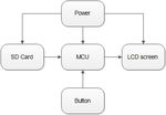
The electronic photo album in this paper is composed of the main control module of STM32, power
supply module, button interface module, LCD display module, and SD card module. The system
framework of this design is shown as in Fig. 1.
Content from this work may be used under the terms of the Creative Commons Attribution 3.0 licence. Any further distribution
of this work must maintain attribution to the author(s) and the title of the work, journal citation and DOI.
Published under licence by IOP Publishing Ltd 1EEICE 2021 IOP Publishing
Journal of Physics: Conference Series 1920 (2021) 012011 doi:10.1088/1742-6596/1920/1/012011
Figure 1. System diagram of electronic photo album based on STM32 processor
TFTLCD is used as the LCD display for projecting JPG and other format pictures, the SD card is
used to store the pictures and output to the LCD for display, and the 3.6V power module is used to
provide power, and the choose of the previous or the next picture can be switched by pressing the button.
In addition to the minimum system board, the required circuit diagram is shown in Figure 2.
Figure 2. The overall circuit diagram of an electronic photo album based on STM32 processor
2.2. Main control module of STM32
This design uses the STM32 series single-chip microcomputer STM32F103ZET6, the core is ARM
Cortex-M3, the highest operating frequency is 72MHz, 64KB RAM, 112 general-purpose IO port pins,
the built-in 8MHz RC oscillator tuned by the factory, serial single-wire debugging (SWD) and JTAG
interface, up to 8 timers: three 16-bit timers, each timer has up to 4 channels for input, capture, output,
comparison, PWM or pulse counting and incremental encoder input, two watchingdog timers, two I2C
interfaces, three USART interfaces, two SPI interfaces.
2.3. LCD display module
The display module used is TFTLCD, and TFT (Thin Film Transistor) is the abbreviation of Thin Film
Transistor. TFT displays are widely used in various electronic devices such as notebook computers and
desktop computers. Each liquid crystal pixel on this type of display is driven by a thin film transistor
integrated behind the pixel, so the TFT display is also a type of active-matrix liquid crystal display
device. It is one of the best LCD color displays[1]. The TFT display has the advantages of high
2EEICE 2021 IOP Publishing
Journal of Physics: Conference Series 1920 (2021) 012011 doi:10.1088/1742-6596/1920/1/012011
responsiveness, large screen brightness, and strong contrast. Its effect on display is close to that of a
CRT display.
2.4. SD card module
The SD card was jointly launched by Panasonic, Toshiba and SanDisk, and was released in August 1999.
The transportation of the data and physical specifications of the SD card are developed by MMC, the
size is similar to that of the MMC card, which is 32mm x 24mm x 2.1mm. The length and width are the
same as the MMC card, except that it is 0.7mm thicker than the MMC to accommodate a larger capacity
storage unit. SD memory card is a new generation of memory device based on semiconductor flash
memory. Due to its small size, fast data transmission speed, hot-swappable and other excellent
characteristics, it is widely used in portable devices, such as digital cameras, Tablet computers and
multimedia players, etc. Connected by SDIO (SDIO_D0~D4(PC8~PC11),SDIO_SCK(PC12),
SDIO_CMD(PD2)), input pictures into the computer by the card reader to the PICTURE folder in SD,
and then insert the SD card into the SD card slot , through the LCD display to read the SD card and
display the saved pictures. The circuit diagram of SD card module is shown as in Fig. 3.
Figure 3. SD card module circuit diagram
2.5. Button interface module
Use Pin_4, Pin_3 and Pin_0 as the function pins to control the switching of the next/previous picture
and pause/continue playing. When the software detects that no buttons are pressed, it will automatically
loop to play the next one every two seconds. The circuit diagram of the key module is shown as in Fig.
4.
Figure 4. Circuit diagram of the button module
3EEICE 2021 IOP Publishing
Journal of Physics: Conference Series 1920 (2021) 012011 doi:10.1088/1742-6596/1920/1/012011
2.6. Power module
The power supply required for this design is 3.6V and 5V DC. We use a current box for power supply,
which is energy-saving and environmentally friendly, and will not pollute the environment. The circuit
diagram of the power module is shown as in Fig. 5.
Figure 5. Circuit diagram of power module
3. Design of software
3.1. Ideas of software design
First of all, the program of this design detects the font library, and then detects whether there is a SD
card. If there is a SD card, it starts to search for the PICTURE folder in the root directory of the SD card.
If found, it will display the picture files with their names under the folder (support bmp, jpg, jpeg or gif
format), and display all the pictures in the PICTURE folder in a loop. Press KEY0 and KEY1 to quickly
switch between the next and previous pictures, press KEY_UP to pause/continue playback, DS1 is used
to indicate Whether it is currently suspended. If the PICTURE folder/any picture file is not found, it will
prompt "No Picture"; if there is an error in the memory allocation, it will prompt "Failure". Similarly,
we also use DS0 to indicate that the program is running.
This design can also use USMART to call ai_load_picfile and minibmp_decode to decode pictures
of any specified path.
The overall program flow chart of this design is shown as in Fig. 6.
4EEICE 2021 IOP Publishing
Journal of Physics: Conference Series 1920 (2021) 012011 doi:10.1088/1742-6596/1920/1/012011
Figure 6. Flow chart of electronic photo album software
3.2. SD card reading
This design uses the FatFS file system module to implement the FAT file system. FatFS is written in
accordance with ANSIC, so it does not depend on hardware and can be ported to most processors. The
FAT structure and each file use separate buffering, which is suitable for quickly accessing multiple files,
supporting multiple drives and partitions, supporting FAT12, FAT16 and FAT32; supporting 8.3 format
file names (LFN does not support) [2], supporting two Partition rules: Fdisk and super floppy disk.
3.3. LCD display reading
The TFTLCD display uses a scanning method to read pictures in various formats, and reads data by
sending GRAM commands.
5EEICE 2021 IOP Publishing
Journal of Physics: Conference Series 1920 (2021) 012011 doi:10.1088/1742-6596/1920/1/012011
3.4. Picture format decoding
The picture formats that can be decoded in this design include BMP/JPG/JPEG/GIF formats, where
BMP, JPG, and JPEG are static pictures, and GIF is a dynamic picture. The decoding principle of BMP
is to use standard BMP decoding [3] . First, obtain the image width and height of the BMP by reading the
data address, and quickly decode the 16-bit, 24-bit, and 32-bit color images. The picture is finally
displayed on the LCD screen by accumulating the pixels on the horizontal and vertical axis. JPEG files
are decoded by pointers. The decoding work area requires at least 3092 bytes and must be aligned with
four bytes. The information to be decoded is defined by the FIL structure in FatFS. The decoding process
is implemented by filling, the width and height of the filling are used to determine the width and height
of the picture, the picture is displayed by drawing dots, and finally the memory is released through
malloc.
4. Physical design
After carefully checking the circuit diagram and PCB diagram, simulate the program on KEIL 5, and
finally burn the program into the STM32 minimum system board. The design result will be displayed
on the LCD phosphor screen. After inspection, no abnormality occurs.
The PCB diagram of this design is shown in Figure 7.
Figure 7. PCB diagram of electronic photo album based on STM32
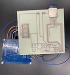
The physical map of this design is shown in Figure 8.
6EEICE 2021 IOP Publishing
Journal of Physics: Conference Series 1920 (2021) 012011 doi:10.1088/1742-6596/1920/1/012011
Figure 8. The physical image of an electronic photo album based on STM32
5. Conclusion
This design proposes a multi-functional STM32-based electronic photo album, which not only keeps up
with the trend of the times, but also makes certain improvements on the increasingly indispensable
electronic photo albums, which can not only meet the requirements of projecting pictures on the LCD
screen. And it can be shown in a loop, you can also switch the next/previous picture manually by
pressing the button, and it also has the function of sensing the temperature and displaying it on the screen.
This design has low power consumption, simple operation and diverse functions, which has considerable
guiding significance and research value for learning STM32 and its applications.
References
[1] Wang,B. (2016) Design of digital photo frame display system based on STM32 single chip
microcomputer[J].Computer Knowledge and Technology, 12(17):241-242.
[2] Chen,XF. (2012) The design of electronic photo frame based on STM32F103[J].Journal of
Dongguan University of Technology, 19(01):49-52.
[3] Zhang,ZC.Wang,PF. (2016) Electronic photo album based on stm32 single chip
microcomputer[J].Electronic Technology and Software Engineering, (04):251-252.
[4] Yan, Lh.Zhang,LF. Wang,JX (2014) Design of Electronic Album Based on Embedded QT.
In:2014 Sixth International Conference on Measuring Technology and Mechatronics
Automation.Zhangjiajie, China. pp. 234-
7You can also read


