Data Sheet AM2108 - Humidity and Temperature Module
←
→
Page content transcription
If your browser does not render page correctly, please read the page content below
Data Sheet AM2108
  Humidity and Temperature Module
  • Relative humidity and temperature output
  • Superior sensor performance, typical accuracy RH: ±2%, T: ±0.3℃
  • Fully calibrated and processed digital output, I²C protocol
  • Wide voltage support 2.2 to 5.5V DC
  • Excellent long-term stability
  • Fast-response and anti-interference capability

    Product Summary
    AM2108 is a temperature and humidity composite sensor with calibrated digital signal output. It
    applies dedicated digital module acquisition technology and RH&T sensor technology, to ensure the
    high reliability and excellent long-term stability. The module outputs a calibrated digital standard I²C
    signal. AM2108 is equipped with a newly designed ASIC dedicated chip, an improved MEMS
    semiconductor capacitive humidity sensor element and a standard on-chip temperature sensor
    element. Its performance has reached the industry's advanced level. The improved new generation
    temperature and humidity sensor makes its performance in harsh environments more stable and
    maintains good accuracy in a larger measurement range. We (Aosong Electronics) have made wide-
    voltage and low-power improvements to the new generation sensors, so that the terminal equipment
    will get energy-saving operation. To ensure the high quality, each sensor has been precisely
    calibrated and tested many times before leaving the factory. The module has exquisite appearance,
    convenient connection and wide application field.

1 Product Description
    The AM2108 is a kind of sensor of humidity and temperature with digital I²C output. It can be
    applied to HVAC, dehumidifier, testing and inspection equipment, consumer products,
    automobiles, automatic control, data loggers, weather stations, home appliances, humidity control,
    medical and other application fields which need to detect and control temperature and humidity.

                                                Figure 1. AM2108

www.aosong.com                             Version:V1.0 —— May 2021                                       1 / 13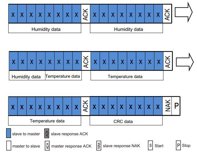
AM2108 Data Sheet
    Sheet
 2 Sensor Specifications
  Relative Humidity
                                                                                       Typical
     Parameter                        Condition                    Min                             Max       Unit
                                                                                       Value
     Resolution                        Typical                      -                   0.024           -   %RH
          Accuracy                     Typical                      -                        ±2         -   %RH

         Tolerance1                     Max                             See Figure 2                    -   %RH

     Repeatable                            -                        -                       ±0.1        -   %RH

     Hysteresis                            -                        -                        ±1         -   %RH

     Nonlinear                             -                        -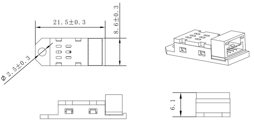
AM2108 Data Sheet
Sheet
Typical
Parameter Condition Min Max Unit
Value
Resolution Typical - 0.01 - °C
Accuracy Typical - ±0.3 - °C
Tolerance1 Max See Figure 3 - °C
Repeatable - - ±0.1 - °C
Hysteresis - - ±0.1 - °C
Response Time2 63% 5 - 30 °C
Scope of Work Extended3 -40 - 80 °C
Prolonged Drift4 Normal -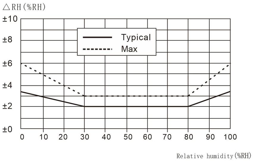
AM2108 Data Sheet
    Sheet

3 Expansion Performance
  3.1 Operating Conditions
  The performance of the sensor is stable within the recommended working condition shown in figure 4. Long-term
  exposure to the condition that outside of the normal range of conditions, especially humidity is over 80%, may
  cause the output signal temporary drift (drift + 3% RH after 60 hours). After returning to the normal working
  condition, the sensor will slowly recover to the calibration status. Refer to "Recovery Processing" in section 4.3 to
  accelerate the recovery process. Long-term operating under the abnormal conditions will accelerate the aging of
  the sensor.

                                                   Figure 4. Working conditions
  3.2 RH Accuracy at Different Temperatures
  Figure 2 defines the RH accuracy at 25°C, and Figure 5 shows the typical humidity error for other temperature
  ranges.

                            Figure 5. The typical error of humidity in the range of 0~80°C, unit: (%RH)
  Please note: The above error is the typical error (excluding hysteresis) of the reference instrument test with a high-precision dew
                                                             point meter.

  3.3 Electrical Characteristics
  The power consumption given in Table 2 is related to temperature and supply voltage VDD. Refer to Figures 6 and
  7 for power consumption estimation. The curves in Figures 6 and 7 are typical natural characteristics, and there
  may be deviations.

www.aosong.com                                      Version:V1.0 —— May 2021                                                  4 / 13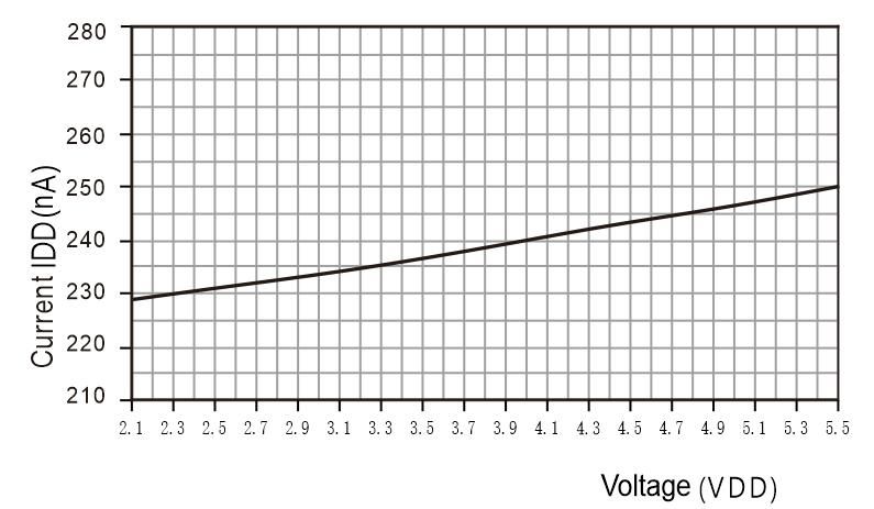
AM2108 Data Sheet
Sheet

                  Figure 6. Typical supply current vs. temperature curve (sleep mode) when VDD=3.3V
              Please note: There is a deviation of approximately ±25% between these data and the displayed value.

                            Figure 7. The relationship between current and voltage at 25℃
   Please note: The deviation of these data from the displayed value may reach ±50% of the displayed value. At 60℃, the
                                       coefficient is about 15 (Compared with table 2).

4 Applications
  4.1 Welding Instructions
  It is forbidden to use reflow soldering or wave soldering for soldering. The manual soldering must be contacted for
  less than 5 seconds at the highest temperature of 300℃.
  Note: After welding, AM2108 need to be stored in the condition >75%RH for over 12 hours to ensure the
  rehydration of the polymer. Otherwise, the output signal of the sensor will drift. The sensor can also be placed in a
  natural environment (>40%RH) for more than 2 days to rehydrate it. The use of low temperature solder (for
  example: 180°C) can reduce the hydration time.
  Do not use the sensor in corrosive gas or condensed water.
  4.2 Storage Conditions and Operating Instructions
  The level of the humidity sensitivity (MSL) is 1, according to the IPC/JEDEC J-STD-020 standard. Therefore, it is
  recommended to use it within one year after shipment.
  This kind of the sensor is not an ordinary electronic component and needs to be carefully protected. Users must
  pay more attention to this key point. Long-term exposure to high concentrations of chemical vapor will cause the
  output signal of the sensor drift. Therefore, it is recommended to store the sensor in the original packaging including
  a sealed ESD bag, and meet the following conditions: temperature range 10℃ - 50℃ (a limited time within 0-
  85℃ ); humidity 20-60%RH (the sensor without ESD package). For those sensors which had been removed from
  the original packaging, we recommend to store them in an antistatic bag made of PET/AL/CPE containing metal.
  During production and transportation, the sensor should be avoided to contact with high concentrations of chemical

                                                                                                                          5 / 13
www.aosong.com                                   Version:V1.0 —— May 2021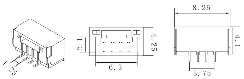
AM2108 Data Sheet
      Sheet
  solvents and long-term exposure in the air. It is should to avoid to contact with volatile glues, tapes, stickers or
  volatile packaging materials, such as foam foils and foam materials, etc. The area of production should be well
  ventilated.
  4.3 Recovery Processing
  As mentioned above, if the sensor had been exposed to extreme working conditions or chemical vapors, the output
  signal will drift. It can be restored to the calibration state by the following processing.
  Drying: Keep for 6 hours under 60-65℃ and 75%RH humidity conditions7.
  4.4 Temperature Effect
  The relative humidity of the gas depends to a large extent on the temperature. Therefore, it is necessary to ensure
  that all sensors measuring the same humidity operate at the same condition of temperature. It should to make sure
  that the tested sensor and the reference sensor are at the same conditions when operate the test, and then
  compare the output signals.
  In addition, when the measurement is at high frequency, the temperature of the sensor will rise, so it will affect the
  accuracy. If you want to ensure the variation of the temperature of the sensor is less than 0.1°C, the activation time
  of AM2108 should not exceed 10% of the measurement time. It is recommended to measure the data every 2
  seconds.
  4.5 Materials for Sealing and Encapsulation
  Many materials can absorb moisture and will act as a buffer, which will increase the time of response and lag.
  Therefore, the materials around the sensors should be carefully selected. The recommended materials are: metal
  materials, LCP, POM(Delrin), PTFE(Teflon), PE, PEEK, PP, PB, PPS, PSU, PVDF, PVF.
  Material used for sealing and bonding (conservative recommendation): It is recommended to use epoxy resin or
  silicone resin to encapsulate electronic components. The gases released by these materials may also contaminate
  AM2108(see 4.2). Therefore, the sensor should be assembled last, and stored in a well-ventilated place, or dried for
  24 hours in an environment of >50℃ , so as to release the polluted gas before packaging.
  4.6 Wiring Rules and Signal Integrity
  If the signal lines of SCL and SDA are parallel and very close to each other, it may cause signal crosstalk and
  communication failure. The solution is to place VDD and/or GND between the two signal lines, separate the signal
  lines, and use shielded cables. In addition, reduce SCL frequency may also improve the integrity of signal
  transmission.This capacitor should be as close as possible to the sensor. See the next chapter.

 7.75%RH   can be easily generated from saturated NaCl.

www.aosong.com                                   Version:V1.0 —— May 2021                                          6 / 13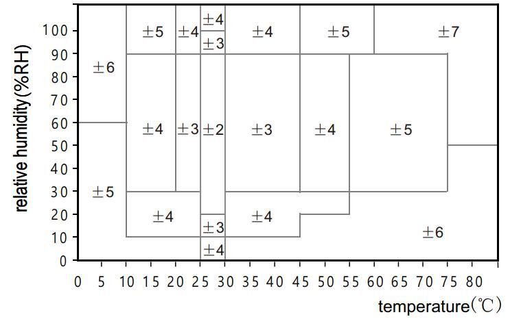
AM2108 Data Sheet
Sheet
5 Interface Definition

         Pins             Name           Describe

         1                VDD            Power supply(2.2v to 5.5v)

         2                SCL            Serial clock Bidirectional port

         3                SDA            Serial Data Bidirectional port

         4                GND            Ground

         Table 4. AM2108 pin distribution (top view)

  5.1 Power Pin(VDD,GND)
  The power supply range of AM2108 is 2.2-5.5V. VDD is powered on prior to SDA and SCL or is powered on
  synchronously to avoid leakage current from the signal line (SCL/SDA), which may cause the chip to be in an
  abnormal working state after power on.
  5.2 Serial Clock SCL
  The serial clock is used to synchronize the communication between the microprocessor and AM2108. Since the
  interface contains completely static logic, there is no minimum SCL frequency.
  5.3 Serial Data SDA
  The SDA pin is used for data input and output of the sensor. When sending a command to the sensor, SDA is valid
  on the rising edge of the serial clock (SCL), and when SCL is high, SDA must remain stable. After the falling edge
  of SCL, the SDA value can be changed. To ensure communication safety, the effective time of SDA should be
  extended by TSU and THO before the rising edge and after the falling edge of SCL refer to Figure 8. When reading
  data from the sensor, SDA is valid (TV) after SCL goes low, and is maintained until the next falling edge of SCL.

                                           Figure 8. Typical application circuit

 Note:
  1. The power supply voltage of the host MCU must be consistent with the sensor when the product is used in the circuit.
  2. If you need to further improve the reliability of the system, you can control the sensor power supply.
  3. When the sensor is just powered on, give priority to the sensor VDD power supply, SCL and SDA high level can be set after
  5ms.

  To avoid signal conflicts, the microprocessor (MCU) must only drive SDA and SCL at low level. An external pull-up
  resistor (for example: 4.7kΩ) is required to pull the signal to a high level. The pull-up resistor has been included in
  the I/O circuit of the AM2108 microprocessor. Refer to Table 7 and Table 8 for detailed information about sensor

                                                                                                                         7 / 13
www.aosong.com                                    Version:V1.0 —— May 2021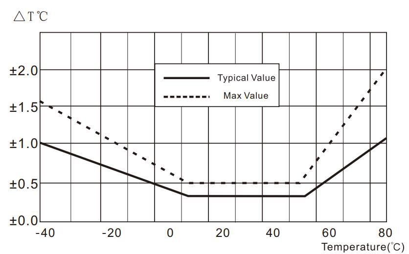
AM2108 Data Sheet
      Sheet
  input/output characteristics.

6 Electrical Characteristics
  6.1 Absolute Maximum Ratings
  The electrical characteristics of AM2108 are defined in Table 2. The absolute maximum ratings given in Table 5 are
  only stress ratings and provide more information. Under such condition, it is not advisable for the device to perform
  functional operations. Exposure to absolute maximum ratings for a long time may affect the reliability of the sensor.

                           Parameters                             Min                    Max                    Unit
                          VDD to GND                              -0.3                    5.5                    V
                       Digital I/O Pins
                                                                  -0.3                VDD+0.3                    V
                     (SDA, SCL) to GND

                     Input current per pin                        -10                     10                    mA
         Table 5. Absolute maximum electrical ratings
  ESD electrostatic discharge conforms to JEDECJESD22-A114 standard (human body model ±4kV),
  JEDECJESD22-A115 (machine model ±200V). If the test condition exceeds the nominal limit index, the sensor
  needs to add an additional protection circuit.
  6.2 Input/Output Characteristics
  Electrical characteristics, such as power consumption, input and output high and low voltages, etc., depend on the
  power supply voltage. In order to make the sensor communication smooth, it is very important to ensure that the
  signal design is strictly limited to the range given in Table 6, 7 and Figure 9).

   Parameters                          Conditions                    Min             Typical           Max              Unit
                                       VDD=3.3V,
   Low output Voltage VOL                                                0               -              0.4               V
                                       -4mA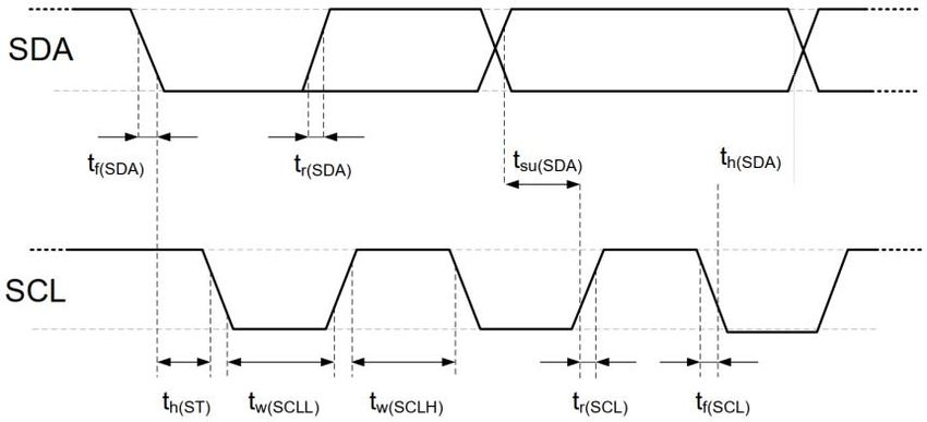
AM2108 Data Sheet
Sheet
line is controlled by the single-chip microcomputer. Please note that the SDA valid read time is triggered by the
falling edge of the previous conversion.
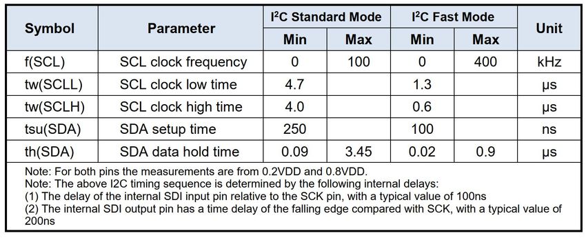
Table 7. Timing characteristics of I²C fast mode digital Inputs / outputs.
The meaning is shown in Figure 9. Unless otherwise noted.
7 Sensor Communication
AM2108 uses standard I²C protocol for communication. For information about the I²C protocol other than the
following chapters, please refer to the following website: www.aosong.com provides a sample program for
reference.
7.1 Start the Sensor
The first step is to power up the sensor with the selected VDD supply voltage (range between 2.2V and 5.5V). After
power-on, the sensor needs less than 100ms stabilization time (SCL is high at this time) to reach the idle state and
it is ready to receive commands sent by the host (MCU).
7.2 Start/Stop Sequence
Each transmission sequence starts with the Start state and ends with the Stop state, as shown in Figure 10 and
Figure 11.
Figure 10. Start transmission status (S)
When SCL is high, SDA is converted from high to low. The start state is a special bus state controlled by the master,
indicating the start of the slave transfer (after Start, the BUS is generally considered to be in a busy state).
Figure 11. Stop transmission state (P)
When SCL is high, the SDA line changes from low to high. The stop state is a special bus state controlled by the
master, indicating the end of the slave transmission (after Stop, the BUS is generally considered to be in an idle
state).
7.3 Send Command
After the transmission is started, the first byte of I²C that is subsequently transmitted includes the 7-bit I²C device
9 / 13
www.aosong.com Version:V1.0 —— May 2021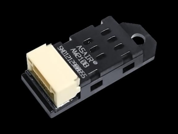
AM2108 Data Sheet
      Sheet
  address 0x38 and a SDA direction bit x (read R: ‘1’, write W: ‘0’). After the 8th falling edge of the SCL clock, pull
  down the SDA pin (ACK bit) to indicate that the sensor data is received normally. After sending the measurement
  command 0xAC, the MCU must wait until the measurement is completed.

       Bits                         Significance                                     Description
                                                                  1-Equipment is busy, in measurement
      Bit[7]                       Busy indication                mode
                                                                  0- Equipment is idle, in hibernation state
     Bit[6:5]                          Retain                     Retain
      Bit[4]                           Retain                     Retain
                                                                  1 - Calibrated
      Bit[3]                        CAL Enable
                                                                  0 - Uncalibrated
     Bit[2:0]                          Retain                     Retain

 Table 8. Status bit description
  7.4 Sensor Reading Process
  1.After power-on, wait no less than 100ms. Before reading the temperature and humidity value, get a byte of status
  word by sending 0x71. If the status word and 0x18 are not equal to 0x18, initialize the 0x1B, 0x1C, 0x1E registers,
  details Please refer to our official website routine for the initialization process; if they are equal, proceed to the next
  step.
  2.Wait 10ms to send the 0xAC command (trigger measurement). This command parameter has two bytes, the first
  byte is 0x33, and the second byte is 0x00.
  3.Wait 80ms for the measurement to be completed, if the read status word Bit [7] is 0, it means the measurement is
  completed, and then six bytes can be read continuously; otherwise, continue to wait.
  4.After receiving six bytes, the next byte is the CRC check data. The user can read it out as needed. If the receiving
  end needs CRC check, an ACK will be sent after the sixth byte is received. Reply, otherwise send NACK to end, the
  initial value of CRC is 0XFF, and the CRC8 check polynomial is:
                                                CRC [7:0] = 1+X4+X5+X8

  5.Calculate the temperature and humidity value
  Note: The calibration status check in the first step only needs to be checked when the power is turned on. No
  operation is required during the acquisition process.

                                                     Trigger measurement data

www.aosong.com                                       Version:V1.0 —— May 2021                                           10 / 13
AM2108 Data Sheet
Sheet
Read temperature and humidity data
Note: The sensor needs time to collect. After the host sends a measurement command (0xAC), delay more than 80
milliseconds before reading the converted data and judging whether the returned status bit is normal. If the status bit [Bit7] is 0,
it means that the data can be read normally. When it is 1, the sensor is busy, and the host needs to wait for the data processing
to complete.
8 Signal Conversion
8.1 Relative Humidity Conversion
The relative humidity RH can be calculated according to the relative humidity signal SRH output by SDA through the
following formula (the result is expressed in %RH):
SRH
RH[%] ( ) *100%
220
8.2 Temperature Conversion
The temperature T can be calculated by substituting the temperature output signal ST into the following formula:
(The result is expressed in temperature ℃ ):
ST
T[℃] ( )* 200 - 50
220
9 Environmental Stability
If the sensor is used in equipment or machinery, make sure that the sensor used for measurement and reference-
sense the same temperature and humidity. If the sensor is placed in the equipment, the response time will be
prolonged, so ensure that sufficient measurement time is reserved in the program design. The AM2108 sensor is
tested according to the company standard of the temperature and humidity sensor of Aosong. The performance of
the sensor under other test conditions is not guaranteed and cannot be used as a part of the sensor's performance.
Especially for specific occasions required by users, no promises are made.
10 Packing Instructions
10.1 Outer Dimensions
AM2108 uses pallet packaging, each tray packed with 50 sensors, each ten plastic tray attached to a vacant plastic
tray as a sealing cover, that is, 11 plastic tray sealed in an anti-static shielding bag and packing, a total of 500
sensors. A package diagram with sensor positioning is shown in Figure 12. Blister tray is placed in an anti-static
11 / 13
www.aosong.com Version:V1.0 —— May 2021AM2108 Data Sheet
Sheet
shielding bag.
AM2108 Package Quantity
Blister tube packing 50 PCS/tube (MAX)
Figure 12. AM2108 sensor package diagram (unit: mm unmarked tolerance: ± 0.2mm)
Figure 13. AM2108 sensor encapsulation (unit: mm not specified tolerance: ± 0.5 mm)
10.2 Tracking Information
All ATH21B sensors have laser marking on the surface, and are accompanied by markings for parameter
descriptions, see Figure 14.
Figure 14. Sensor laser marking
www.aosong.com Version:V1.0 —— May 2021 12 / 13AM2108 Data Sheet
Sheet
Important Notices
Warning, Personal Injury
Do not apply this product to safety protection devices or Quality Assurance
emergency stop equipment, and any other applications
that may cause personal injury due to the product's failure. The company provides a 12-month (1 year) quality
Do not use this product unless there is a special purpose guarantee (calculated from the date of shipment) to direct
or use authorization. Refer to the product data sheet and purchasers of its products, based on the technical
application guide before installing, handling, using or specifications in the product data manual published by
maintaining the product. Failure to follow this Aosong. If the product is proved to be defective during the
recommendation may result in death and serious personal warranty period, the company will provide free repair or
injury. replacement. Users need to satisfy the following conditions:
If the buyer intends to purchase or use Aosong products Notify our company in writing within 14 days after the
without obtaining any application licenses and defect is found.
authorizations, the buyer will bear all the compensation for
The defect of this product will help to find out the
personal injury and death arising therefrom, and exempt
deficiency in design, material and technology of our
Aosong managers and employees and affiliated
product.
subsidiaries from this, Agents, distributors, etc. may incur
any claims, including: various costs, compensation fees, The product should be sent back to our company at
attorney fees, etc. the buyer’s expense.
The product should be within the warranty period.
ESD Protection
The company is only responsible for products that are
Due to the inherent design of the component, it is sensitive defective when used in applications that meet the technical
to static electricity. In order to prevent the damage caused conditions of the product. The company does not make any
by static electricity or reduce the performance of the guarantees, guarantees or written statements about the
product, please take necessary anti-static measures when application of its products in those special applications. At
using this product. the same time, the company does not make any promises
about the reliability of its products when applied to products
or circuits.
This manual may be changed at any time without notice.
Copyright® 2021, ASAIR®
13 / 13
www.aosong.com Version:V1.0 —— May 2021You can also read