D5 SMART INSTALLATION MANUAL - Centurion Systems (Pty) Ltd www.centsys.com
←
→
Page content transcription
If your browser does not render page correctly, please read the page content below

SLIDING GATE OPERATORS

  D5 SMART
  INSTALLATION MANUAL

Centurion Systems (Pty) Ltd
www.centsys.com
Company Profile

     1986                  1990                  1995                  1999                 Today

In-house                                                                              Manufactures to
R&D                                                                                      international
development                                                                           quality standard
team                                                                                   ISO 9001:2015

                                              ISO 9001:2015

After-sales                                                                                      100%
multi-language                                                                               testing of
Technical Support                                                                             products

                                                                        Sales and technical support
                                                                             to Africa, Europe, Asia,
                                                                            the Americas, Australia
                                                                                      and the Pacific

                                                                        Call Centre Operating Times

                                                                                        Monday to Friday
                                                                                   07h00 to 18h00 GMT+2,

                                                                                               Saturdays
                                                                                    08h00 to 16h30 GMT+2

Centurion Systems (Pty) Ltd reserves the right to make changes to the product described in this
manual without notice and without obligation to notify any persons of any such revisions or changes.
Additionally, Centurion Systems (Pty) Ltd makes no representations or warranties with respect to
this manual. No part of this document may be copied, stored in a retrieval system or transmitted in any
form or by any means electronic, mechanical, optical or photographic, without the express prior written
consent of Centurion Systems (Pty) Ltd.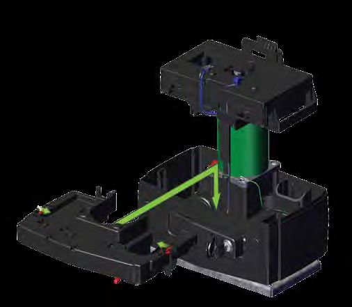
Contents
1.       INTRODUCTION                                          Page 5
1.1.     Important Safety Information                          Page 6
1.2.     Lightning Protection                                  Page 8
1.3.     Theft Protection                                      Page 8

2.       SPECIFICATIONS                                        Page 9

2.1.     Physical Dimensions                                   Page 9

2.2.     Technical Specifications                              Page 9
3.       PRODUCT IDENTIFICATION                              Page 11

4.       REQUIRED TOOLS AND EQUIPMENT                        Page 12

5.       NEW SITE INSTALLATION PREPARATION                   Page 13

5.1.     General Considerations for the Installation         Page 13

5.2.     Endstops                                            Page 14

5.3.     Guide-rollers and Anti-lift Brackets                Page 14

5.4.     Starting and Running Forces                         Page 15

5.5.     Cabling Requirements                                Page 16

6.       LUBRICATION                                         Page 17

7.       OPERATOR INSTALLATION                               Page 18

7.1.     New Site Installations                              Page 18
7.1.1.   Locating an Initial Reference Point                   Page 18
7.1.2.   Minimum Clearances                                    Page 19
7.1.3.   Locate the Operator's Position                        Page 20
7.1.4.   Foundation Plate Installation                         Page 24

7.2.     Retro-fit Installations (Existing Sites)            Page 26

7.3.     Conduit and Cable Length                            Page 26

7.4.     Preparing the D5 SMART for Installation             Page 27
7.4.1.   Removing the Charger                                  Page 27
7.4.2.   Removing the Lower Battery Tray                       Page 28
7.4.3.   Removing the Control Card                             Page 29

7.5.     Mounting the Gearbox                                Page 30

7.6.     Routing the Cables                                  Page 32

7.7.     Manual Override                                     Page 34

7.8.     Height Adjustment                                   Page 35

                                               page 3   www.centsys.com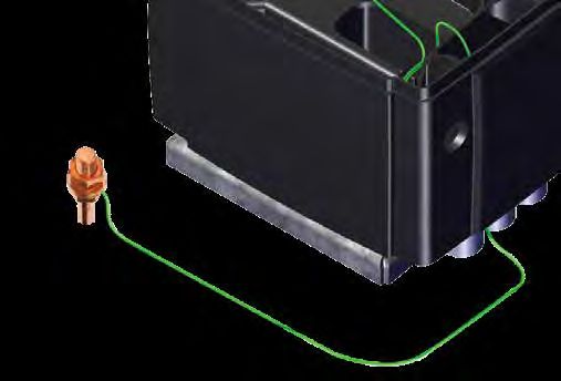
CONTENTS

7.9.     Mounting the Rack                                                          Page 36
7.9.1.   Fitting Different Types of Rack to the Gate                                  Page 37
7.9.2.   Finalising the Height Adjustment                                             Page 40

7.10. Re-assembling the D5 SMART                                                    Page 42
7.10.1. Override Sensor                                                               Page 42
7.10.2. Routing the Override Sensor Harness                                           Page 42
7.10.3. Placing the Lower Battery Tray and Charger back into Position                 Page 43
7.10.4. Placing the Control Card back into Position                                   Page 44
7.10.5. Reconnecting the Harnesses to the Control Card and Charger                    Page 45

8.       COMPLETING THE INSTALLATION                                                Page 46

8.1.     Fitting the Batteries                                                      Page 46

8.2.     Accessory Installation and Storage                                         Page 47

8.3.     Wiring the Control Card on its Default Settings                            Page 48
8.3.1.   Closing Infrared Beam Wiring (i5 Infrared Beams)                             Page 48
8.3.2.   Closing Infrared Beam Wiring (Photon Infrared Beams)                         Page 49
8.3.3.   External Radio Receiver and Loop Detector Wiring                             Page 50
8.3.4.   Earth Spike Installation                                                     Page 51
8.3.5.   G-ULTRA to D5 SMART Wiring                                                   Page 52

8.4.     Commissioning the System                                                   Page 52

8.5.     Apply Warning Decal                                                        Page 53

9.       GENERAL MAINTENANCE                                                        Page 54

9.1.     Gate Maintenance                                                           Page 54

9.2.     D5 SMART Maintenance                                                       Page 55

10.      INSTALLATION HANDOVER                                                      Page 56

11.      WARRANTY INFORMATION                                                       Page 57

Icons used in this manual

           This icon indicates tips and other information that could be useful during the
           installation.

           This icon denotes variations and other aspects that should be considered during
           installation.

           This icon indicates warning, caution or attention! Please take special
           note of critical aspects that MUST be adhered to in order to prevent
           injury.

                                                  page 4                      www.centsys.com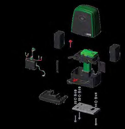
SECTION 1                                                                           INTRODUCTION

1. Introduction
The D5 SMART is a domestic and light-industrial operator designed to open and close sliding
gates weighing up to 500kg. A custom-designed gearbox moulded from robust engineering
polymers, coupled to a powerful 24V DC motor, provides fast and reliable automation for
entrances to homes and small housing estates.

The system operates off two 12V batteries housed inside the operator using a switch-mode
charger to maintain the battery in a fully-charged state. The batteries provide critical power
failure protection.

A non-contact Hall Effect Sensor was selected to ensure reliability and positional accuracy.
The Hall Effect Sensor is highly resistant to dust, oil, dirt or insect ingress, therefore ensuring
that the D5 SMART opens and closes gates reliably and accurately.

Advanced features of the D5 SMART logic controller include:

•    Interactive graphic user interface via a smartphone application
•    Automated setup of gate endpoints (limits)
•    Independently-adjustable motor speed in both opening and closing directions
•    Fail-safe collision detection and auto reverse (adjustable sensitivity)
•    Smooth, adjustable start/stop (ramp-up/ramp-down)
•    Multiple operational modes
•    Selectable, adjustable Autoclose
•    Pedestrian (partial) opening
•    Positive Close Mode
•    Independent safety inputs for opening and closing beams
•    Automatic beam test for both opening and closing beams
•    Advanced lightning/surge protection
•    Onboard NOVA code-hopping radio receiver with full channel-mapping capability
     (limited to 1500 remotes1)
1. Multiple buttons per remote can be used

                                              page 5                              www.centsys.com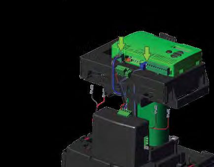
SECTION 1                                                                      INTRODUCTION

1.1. Important Safety Information

            ATTENTION!
            To ensure the safety of people and possessions, it is important that
            you read all of the following instructions.

            Incorrect installation or incorrect use of the product could cause
            serious harm to people.

            The installer, being either professional or DIY, is the last person on
            the site who can ensure that the operator is safely installed and that
            the whole system can be operated safely.

Warnings for the Installer
CAREFULLY READ AND FOLLOW ALL INSTRUCTIONS before installing the
product.

•   All installation, repair, and service work to this product must be carried out by a
    suitably qualified person
•   This appliance is not intended for use by persons (including children) with reduced
    physical, sensory or mental capabilities, or lack of experience and knowledge, unless
    they have been given supervision or instruction concerning use of the appliance by a
    person responsible for their safety
•   Do not activate your gate unless it is in view and you can determine that its area of
    travel is clear of people, pets, or other obstructions
•   NO ONE MAY CROSS THE PATH OF A MOVING GATE —
    always keep people and objects away from the gate and its area of travel
•   NEVER LET CHILDREN OPERATE OR PLAY WITH THE GATE CONTROLS
•   Secure all easily-accessed gate opener controls in order to prevent unauthorised use
    of the gate
•   Do not in any way modify the components of the automated system
•   Do not install the equipment in an explosive atmosphere: the presence of flammable
    gases or fumes is a serious danger to safety
•   Before attempting any work on the system, turn off electrical power to the operator
    and disconnect the batteries
•   The Mains power supply of the automated system must be fitted with an all-pole
    switch with contact opening distance of 3mm or greater; use of a 5A hydraulic
    breaker with all-pole circuit break is recommended
•   Make sure that an earth leakage circuit breaker with a threshold of 30mA is fitted
    upstream of the system
•   Never short-circuit the battery and do not attempt to recharge the batteries with
    power supply units other than that supplied with the product, or manufactured by
    Centurion Systems (Pty) Ltd

                                            page 6                            www.centsys.com
SECTION 1                                                                        INTRODUCTION

•   Make sure that the earthing system is correctly constructed and that all metal parts of
    the system are suitably earthed
•   Safety devices must be fitted to the installation to guard against mechanical
    movement risks such as crushing, dragging and shearing
•   Always fit the warning signs visibly to the inside and outside of the gate
•   The installer must explain and demonstrate the manual operation of the gate in case
    of an emergency and must hand over the User Guide/Warnings to the user
•   The installer must explain these safety instructions to all persons authorised to use
    this gate, and be sure that they understand the hazards associated with automated
    gates
•   Do not leave packing materials (plastic, polystyrene, etc.) within reach of children as
    such materials are potential sources of danger
•   Dispose of all waste products like packing materials, worn-out batteries, etc.,
    according to local regulations
•   Always check the obstruction detection system, and safety devices for correct
    operation
•   Neither Centurion Systems (Pty) Ltd, nor its subsidiaries, accepts any liability caused
    by improper use of the product, or for use other than that for which the automated
    system was intended
•   This product was designed and built strictly for the use indicated in this
    documentation; any other use, not expressly indicated here, could compromise the
    service life/operation of the product and/or be a source of danger
•   Everything not expressly specified in these instructions is not permitted

              WARNING! WARNING! WARNING! WARNING! WARNING!

                                                  KEEP CLEAR!
                                           GATE MAY MOVE AT ANY TIME!

             SAFETY
              FIRST

            MOVING GATE CAN CAUSE SERIOUS INJURY OR DEATH!
                        KEEP CLEAR! GATE MAY MOVE AT ANY TIME!
               DO NOT ALLOW CHILDREN TO OPERATE THE GATE OR PLAY IN THE
                               NEAR VICINITY OF THE GATE.

                                            page 7                           www.centsys.com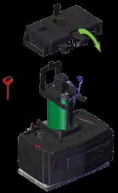
SECTION 1                                                                       INTRODUCTION

1.2. Lightning Protection
The electronic controller utilises the same proven surge protection philosophy that is
used in all our products. While this does not guarantee that the unit will not be damaged
in the event of a lightning strike or power surge, it greatly reduces the likelihood of such
damage occurring. The earth return for the surge protection is provided via the mains
power supply earth and/or earth spike located next to the operator.

        In order to ensure that the surge protection is effective, it is essential
        that the unit is properly earthed.

1.3. Theft Protection
While care has been taken in the design of the D5 SMART to prevent unauthorised
removal (theft) of the unit, an optional steel theft-deterrent cage is also available for
added peace of mind.

        If a theft-deterrent cage is required, be sure to leave enough clearance from
        pillars, etc. (Section 7.1.2. - "Minimum Clearances").

                                            page 8                            www.centsys.com
SECTION 2                                                                SPECIFICATIONS

2. Specifications
2.1. Physical Dimensions
When the WiZos are removed from their packaging, it is important to remember the
following:
The WiZos are ready to be used; they have just not been configured or added to a
network. Configuration is what the user / installer needs to do.

                                                                                 372.5mm
     58mm

        31mm             181mm                          275mm

                                         FIGURE 1. D5 SMART PHYSICAL DIMENSIONS

2.2. Technical Specifications

 Input voltage                                     90V - 240V AC +/-10% @ 50Hz1

 Current consumption (mains)                                    200mA

 Battery charger current output                                 1.3A

 Maximum number of operations per day                           1503,6

 Duty cycle - Mains present2,3                                  50%

                                                           Battery-driven
 Motor power supply
                                                     (Standard Capacity - 2x12V)

 Current consumption (motor at rated load)                       13A

 Input / Output sink currents (Max. accessory current draw)

     I/O 1-4                                              100mA (12/24V)

     I/O 5 and 6                                       3A (12/24V) 10sec Pulse
                                                                               TABLE 1

                                        page 9                           www.centsys.com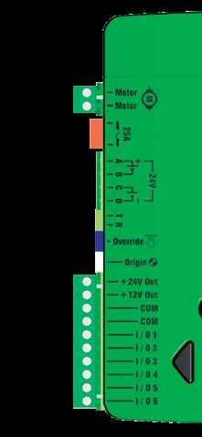
SECTION 2                                                                                                                        SPECIFICATIONS

2.2. Technical Specifications Continued

     Fuse Protection                                                                             Type                             Rating

           Main Control Card                                                                 Serviceable                            25A
                                                                                                                            12V 600mA
                                                                                                                                or
           Aux. Supply                                                                    Resetable Fuse
                                                                                                                              24V 3A
                                                                                                                           (10sec Pulse)
           Charger (Mains Supply)                                                        Non-serviceable                    3A slow-blow

     Motor push force - starting                                                                                 30kgf

     Motor push force - rated                                                                                    17kgf

     Gate mass - maximum                                                                                        500kg

     Gate length - maximum                                                                                       100m

     Gate speed (varies with load)4                                                                    30m/min @ 17kgf

     Manual Override                                                                            Lockable with key release

     Operations in standby (6Ah Batteries)

           Half day5,6                                                                                             44

           Full day5,6                                                                                             35

     Collision Sensing                                                                                        Electronic

     Operating temperature range                                                                        -15°C to +50°C

                                                                                        Code-hopping multichannel receiver
     Onboard receiver type
                                                                                           with selective add and delete

     Receiver code storage capacity                                                                      1500 Remotes7

     Receiver frequency                                                                                     433.92MHz

     Degree of protection                                                                                         IP55

     Mass of unit packed (with standard kit, but
                                                                                                                 9.1kg
     excl. rack and battery)

     Packaging dimensions (with standard kit,                                                 325mm wide x 244mm deep
     but excl. rack and battery)                                                                   x 445mm high
                                                                                                                    TABLE 1 CONTINUED
1.   Can operate off a solar supply, consult your local dealer for assistance
2.   Based on 25°C ambient temperature and unit not in direct sunlight
3.   Based on a motor push force of less than 50% of rated (Starting and Running forces)
4.   Gate opening and closing speeds can be configured to run slower depending on the requirements of individual installations
5.   Can increase battery capacity for longer standby times
6.   Based on 4m gate, excluding all accessories
7.   Multiple buttons per remote can be used

                                                                        page 10                                                  www.centsys.com
SECTION 3 PRODUCT IDENTIFICATION
3. Product Identification
21 1 2 3
22
4
23
1
20
19
18 5
6
17
7
16 8
9
10
24 12
11
12
13
25 15 14
FIGURE 2. PRODUCT IDENTIFICATION
1. 12V Battery 1
14. Mounting Bolt
2. Oil Dipstick 15. Lower Battery Tray
3. D5 SMART Cover 16. Cable Trunking
4. D5 SMART Control Card 17. Earth Harness
5. Cable Shield 18. Switch Mode 1.3A charger
6. Gearbox 19. Battery Harness
7. M10 Nut (17mm Socket) 20. Power Supply Harness
8. Spring Washer 21. Control Card Platform
9. Top Height Adjuster (19mm Socket) 22. Accessory Retaining Door
10. Bottom Height Adjuster 23. Top Battery Stabiliser
11. Heavy Duty M12 Washer 24. Release Handle
12. M10 Half-Nut 25. Camlock
13. D5 SMART Foundation Plate
1. Batteries are not supplied with the D5 SMART. The D5 SMART supports both 6Ah and 7.2Ah variants.
page 11 www.centsys.comSECTION 4 REQUIRED TOOLS AND EQUIPMENT
4. Required Tools and Equipment
Hammer
Ratchet and Screwdrivers
Socket set 6mm Phillips
(17mm and 19mm) 3.5mm Flat
with extensions
Electric Drill
Smartphone
with app
Crimping tool Connector installed
and Pin lugs block
G-clamps
(x2)
Angle grinder
Pin punch Measuring
6mm tape
Masonry drill bits
Hacksaw Welding machine
(including consumables)
and safety equipment
Safety equipment
(goggles, gloves, etc.)
Pliers Marking
pen/chalk
Soldering
iron
Spirit level
Extension cord
FIGURE 3. REQUIRED TOOLS AND EQUIPMENT
page 12 www.centsys.comSECTION 5 NEW SITE INSTALLATION PREPARATION
5. New Site Installation Preparation
5.1. General Considerations for the Installation
Always recommend the fitment of additional safety equipment such as safety edges
and safety beams, for additional protection against entrapment or other mechanical
risks.
Check that no pipes or electrical cables are in the way of the intended installation.
Check that enough space is available for the gate operator, specifically for the release
handle (See Section 7.1.2. - "Minimum Clearances").
Check for loose, sandy soil if installing a foundation, as the soil condition may require
a larger foundation.
Never fit the operator on the outside of the gate, where the public have access to it.
Install the gate operator only if:
• It will not pose a hazard to the public
• There is sufficient clearance to a roadway and/or public thoroughfares
• The installation meets all municipal and/or local authority requirements once completed
• The gate mass and application are within the operator specifications
• The gate is in good working order, meaning:
• that it opens and closes freely;
• does not move on its own if left in any position;
• it can be installed to have sufficient clearance between moving parts when
opening and closing to reduce the risk of personal injury and entrapment;
• Pushbuttons or key-switches, when required, can be positioned so that the gate is in
line-of-sight of the user
page 13 www.centsys.comSECTION 5 NEW SITE INSTALLATION PREPARATION
5.2. Endstops
Fit opening and closing endstops capable of stopping the gate at rated speed. Refer to
the specifications at the beginning of this manual for the operating speed.
Make H1>H2 to ensure gate will not jump over the endstop.
Opening and closing endstops are mandatory and must be fitted to
prevent death or accidental injury as the operator uses and confirms
these limits during operation.
Endstop
Endstop
H1
H2
Ø16mm
FIGURE 4. FITTING ENDSTOPS
5.3. Guide-rollers and Anti-lift Brackets
Guide-rollers must be installed to ensure that the gate is held vertical. For improved
safety, fit additional support posts to prevent the gate from falling over should the
guide-rollers fail.
To prevent unauthorised access, fit anti-lift brackets as shown.
The gap between the anti-lift bracket and the gate must be less than 5mm.
Ensure that the gate cannot be lifted off the motor pinion with the anti-lift
bracket fitted.
Guide-rollers and Side view of gate and different
Anti-Lift Bracket Guide-roller options
GAPSECTION 5 NEW SITE INSTALLATION PREPARATION
5.4. Starting and Running Forces
Test the starting force of the gate as per the diagram. Use a pull scale in both directions
to determine the maximum amount of pull force required to set the gate in motion.
Determine the running force of the gate by continuing to pull on the scale with just
sufficient force to keep it running.
Read and note the maximum value in kgf (kilogram-force) shown on the scale.
Where possible, determine the gate mass.
Our warranty will be void if the pull force and / or gate mass exceeds the below operator
specifications:
• Starting force - 30kgf
• Running (rated) force - 17kgf
• Maximum gate mass - 500kg
Pull Scale
FIGURE 6. STARTING AND RUNNING FORCES
page 15 www.centsys.comSECTION 5 NEW SITE INSTALLATION PREPARATION
5.5. Cabling Requirements
9
9
8 6
3
7
5
1
2
4
10
FIGURE 7. CABLING REQUIREMENTS
Legend
1. MAINS SUPPLY CABLE: 90V - 240V AC mains cable via double-pole mains
isolator-switch (3 core L.N.E. 1.5mm2 SWA)1,2
2. Optional intercom cable from motor to dwelling
(n1 + 6 core3 0.22mm2 multi-strand shielded cable)
3. Optional intercom cable from motor to entry panel
(n2 0.22mm2 multi-strand shielded cable)
4. Optional but recommended infrared safety beams
(3 core 0.22mm2 multi-stranded)4
5. Optional access control device (3 core 0.22mm2 multi-stranded)
6. Optional pedestrian key-switch (2 core 0.22mm2 multi-stranded) OR
7. Optional keypad (3 core 0.22mm2 multi-stranded)4
8. Optional external radio receiver (3 core 0.22mm2 multi-stranded)5
9. Optional pillar lights (3 core LNE SWA, size according to power requirements)6
10. Optional ground loop for free-exit
(1 core 0.5mm2 multi-stranded – silicone coated)7
n1 means the number of cores required by an intercom
n2 means the number of cores required by an intercom
1. Possibly increase cable thickness if pillar lights are installed.
2. Type of cable must adhere to municipal bylaws but typically SWA (steel wire armoured) cable is recommended.
The armouring provides excellent screening, which gives better protection against lightning – earth one end of the screening).
3. Allows for all features such as pedestrian opening, status LED, etc., to be operated from the intercom handset inside the dwelling.
Number of cores and type of cable could vary depending on brand of access control system being used.
4. Wireless accessories are available. Please refer to www.censys.com for further information.
5. For optimum range, an external receiver can be mounted on the wall.
6. Requires an external relay
7. Consult manufacturer of loop detector for specific details.
page 16 www.centsys.comSECTION 6 LUBRICATION
6. Lubrication
The internal gearset of the D5 SMART is lubricated by means of an oil bath.
The D5 SMART is supplied with oil in its gearbox.
The D5 SMART does not require routine oil changes. However, in the event
of the unit losing oil due to stripping down or mechanical damage, the correct
replacement oil is Castrol Syntrax Long Life 75W-90.
If the gearbox is bolted down in the horizontal position during filling,
the correct level is reached when the oil level has reached the stepped section
of the dipstick.
40ml of oil is sufficient for lubrication purposes.
Oil filling procedure
• Lift the cover of the operator
• Release and tilt the Control Card Platform forward to gain access to the
batteries (See Section 8.1 - "Fitting the Batteries")
• Remove the left battery to gain access to the red dipstick
• Remove the dipstick by pulling it upwards
• Pour the required amount of oil into the gearbox
• Refit the dipstick
Control Card
Platform
Motor Bracket Clip
Dipstick
Step Oil Reservoir
(Optimum Opening
Oil Level)
Tip
FIGURE 8. OPERATOR LUBRICATION
page 17 www.centsys.comSECTION 7 OPERATOR INSTALLATION
7. OPERATOR INSTALLATION
7.1. New Site Installations
When installing the D5 SMART, it is important to take note of the information
found in Sections 7.1.1. and 7.1.2. when determining the position of the
Foundation Plate, and the height of the D5 SMART in relation to the gate that is
to be automated.
7.1.1. Locating an Initial Reference Point
Firstly, it is necessary to establish a reference point. To do this, manually open and close
the gate so that it moves past a stationary point (i.e. a vertical spike), and determine
which part of the gate (including its wheels) protrudes the furthest towards where the
D5 SMART will be installed. Refer to the examples shown below.
Check for wheels, palisade, uprights, etc. that could potentially collide
with the pinion.
Palisade Gate Rail Palisade Gate Rail
Gate Warped Gate
GATE MOVEMENT GATE MOVEMENT
Foundation Foundation
for D5 SMART for D5 SMART
Edge that Edge that
protrudes
protrudes
out protrudes
thethe
furthest
most the furthest
(Reference Point) (Reference Point)
Palisade
Gate Gate Rail Palisade Gate Rail
Gate Gate
GATE MOVEMENT GATE MOVEMENT
Foundation Foundation
for D5 SMART Palisade for D5 SMART Gate Wheel
Edge that Edge that
protrudes
protrudes
out protrudes
protrudes
out
Possible thethe
furthest
most Possible thethe
furthest
most
Collision (Reference Point) Collision (Reference Point)
FIGURE 9. FINDING A REFERENCE POINT
Once the point which protrudes the furthest has been found, this will be the
reference point to be used when finding the optimum position for the
D5 SMART.
page 18 www.centsys.comSECTION 7 OPERATOR INSTALLATION
7.1.2. Minimum Clearances
Below are site plan examples illustrating the minimum clearances required when
installing the D5 SMART.
Gate Rack
Pillar Pillar
80mm 80mm
Foundation
Theft-deterrent Cage D5 SMART
FIGURE 10. MINIMUM CLEARANCES - SIDES
Gate Rack
Foundation
Trench Trench
120mm
Most extreme path of
the Override Lever
Trench
FIGURE 11. MINIMUM CLEARANCES - FRONT
page 19 www.centsys.comSECTION 7 OPERATOR INSTALLATION
7.1.3. Locating the Operator's Position
To ensure that the operator does not protrude into the driveway, install the base plate at
least flush with the driveway entrance.
It is typical to mount the rack above the pinion as shown in Figures 12, 14 and 16 for
each type of rack considered. However, in each case, Figures 13, 15 and 17 show the
rack mounted underneath.
If there is space to mount the rack underneath without fouling the ground as the
gate moves, the following are the pros and cons:
Pros
• The rack is more hidden from view
• It provides a very effective anti-lift bracket
• It ensures that, since the gate beds in, the rack does not drop onto the
pinion, loading the operator unnecessarily
Cons
• Rack teeth face up vertically, potentially collecting dirt
• Could require the use of a custom bracket
The measurements given below are based on the three different racks
supplied by Centurion Systems (Pty) Ltd and are to be used as
guidelines only.
Steel Rack
25mm
25mm (Recommended to allow
(Typical Steel
Rack Width)
Minimum space from edge
for adjustment)
of foundation plate to
reference point of edge that
protrudes the furthest.
(Section 7.1.1.)
49mm-51mm
11mm
167.2mm1
115.2mm1,2
83mm
Flat bar welded
to foundation plate
and rail
Concrete Foundation Foundation Plate
FIGURE 12. STEEL RACK ABOVE PINION
1. Includes 3mm clearance required between rack and pinion
2. Distance between bottom of the Foundation Plate and bottom edge of the Rack Tooth
page 20 www.centsys.comSECTION 7 OPERATOR INSTALLATION
25mm (Recommended to allow 25mm
(Typical Steel
Rack Width)
for adjustment)
Minimum space from edge
of foundation plate to reference
point of edge that protrudes
the furthest.
(Section 7.1.1.)
51.4mm1,2
49mm-51mm
11mm
Foundation Plate
Raised Concrete
Foundation
FIGURE 13. STEEL RACK BELOW PINION
1. Includes 3mm clearance required between rack and pinion
2. Distance between bottom of the Foundation Plate and top edge of the Rack Tooth
RAZ Rack
29.5mm
25mm (Recommended to allow
(Typical RAZ
Rack Width)
Minimum space from edge
for adjustment)
of foundation plate to
reference point of edge that
protrudes the furthest.
(Section 7.1.1.)
53mm-55mm
11mm
167.7mm1
115.2mm1,2
83mm
Flat bar welded
to foundation plate
and rail
Concrete Foundation Foundation Plate
FIGURE 14. RAZ RACK ABOVE PINION
1. Includes 3mm clearance required between rack and pinion
2. Distance between bottom of the Foundation Plate and bottom edge of the Rack Tooth
page 21 www.centsys.comSECTION 7 OPERATOR INSTALLATION
25mm (Recommended to allow 29.5mm
(Typical Steel
Rack Width)
for adjustment)
Minimum space from edge
of foundation plate to reference
point of edge that protrudes
the furthest.
(Section 7.1.1.)
53mm-55mm
51.4mm1,2
11mm
Foundation Plate
Raised Concrete
Foundation
FIGURE 15. RAZ RACK BELOW PINION
1. Includes 3mm clearance required between rack and pinion
2. Distance between bottom of the Foundation Plate and top edge of the Rack Tooth
Nylon Angle Rack
If using nylon angle rack, please ensure that the weight and pull force of the
gate does not exceed the strength limit of the rack.
29mm
25mm (Recommended to allow
(Typical Nylon
Rack Width)
Minimum space from edge
for adjustment)
of foundation plate to
reference point of edge that
protrudes the furthest.
(Section 7.1.1.)
53mm-55mm
11mm
165.2mm1
115.2mm1,2
83mm
Flat bar welded
to foundation plate
and rail
Concrete Foundation Foundation Plate
FIGURE 16. NYLON RACK ABOVE PINION
1. Includes 3mm clearance required between rack and pinion
2. Distance between bottom of the Foundation Plate and bottom edge of the Rack Tooth
page 22 www.centsys.comSECTION 7 OPERATOR INSTALLATION
25mm (Recommended to allow 29mm
(Typical Nylon
Rack Width)
for adjustment)
Minimum space from edge
of foundation plate to reference
point of edge that protrudes
the furthest.
(Section 7.1.1.)
53mm-55mm
51.4mm1,2
11mm
Foundation Plate
Raised Concrete
Foundation
FIGURE 17. NYLON RACK BELOW PINION
1. Includes 3mm clearance required between rack and pinion
2. Distance between bottom of the Foundation Plate and top edge of the Rack Tooth
page 23 www.centsys.comSECTION 7 OPERATOR INSTALLATION
7.1.4. Foundation Plate Installation
The foundation plate can either be set into a new concrete foundation, as in
Section 7.1.4.1, or bolted down onto an existing concrete plinth as in Section
7.1.4.2.
Mounting Bolt Cutouts for Conduit
(New and Existing Installations)
Bolt-down point for
existing Concrete Plinth
Towards Gate
Mounting Bolt
Bolt-down point for
existing Concrete Plinth
Tab Legs
Tab
Bolt-down point for
Mounting Bolt existing Concrete Plinth
Tab Legs Tab
FIGURE 18. FOUNDATION PLATE ASSEMBLY - TOP VIEW
7.1.4.1. New Concrete Foundation
View once tabs
Check that the M10 half- have been bent
nuts are tightened to 20Nm down correctly
on the mounting bolts.
Using a pair of pliers, gently bend
the two tabs of the foundation plate
down to a 90° angle as shown in
Figure 19.
Be careful not to deform
the Foundation Plate
Bottom face of the
while bending the tabs. Foundation Plate
FIGURE 19
Foundation Plate View once legs
have been bent
correctly
Again, using a pair of pliers, gently
bend the two legs on each tab to an
angle of 90° in opposite directions as
shown in Figure 20.
Be careful not to deform Tab
the Foundation Plate
while bending the tabs.
Tab
Legs
FIGURE 20
page 24 www.centsys.comSECTION 7 OPERATOR INSTALLATION
Lay the cabling conduit so
that it routes the cables to
the back of the Foundation
Plate. Ensure that 30mm
of conduit protrudes above
the concrete.
300mm
Using medium-strength concrete
(25MPa), cast the plinth according to
40
the dimensions as shown in Figure 21. 0m
m
Cabling conduit exiting
at the back of the
Foundation Plate
When using a concrete
FIGURE 21
foundation, it is
recommended that the
foundation plate is welded Rail
to the rail/track ofsafety
the devices
gate to ensure correct operation
using a short length of flat
bar, as shown in Figure 22.
This makes it possible
to complete the whole
mechanical and electrical
installation without having
to wait for the concrete to
set. After completing the Flat bar welded to
installation, the concrete foundation plate
and rail
can be poured and the Foundation Plate
operator left in manual
FIGURE 22
mode until the concrete
has set. Do not operate the
motor until concrete has
completely set.
7.1.4.2. Existing Concrete Plinth
Nut Mounting
Bolt
If bolting onto an existing concrete
Washer
plinth, place the foundation plate
down in the correct position and use
the plate as a template for marking
the rawl bolt holes.
Check that the M10 half-
nuts are tightened to 20Nm
on the mounting bolts.
Rerouting of existing cables
may be necessary.
Expansion Stud
FIGURE 23
page 25 www.centsys.comSECTION 7 OPERATOR INSTALLATION
7.2. Retro-fit Installations (Existing Sites)
The D5 SMART has been designed to retro-fit into most existing D3, D5, or D5-Evo
installations, with the following provisions;
• If the unit is installed with the gate in the closed position and the unit on the left-
hand side (from the inside of the property), the rack should extend at least 75mm
past the centre line of the existing pinion
• If the existing unit is mounted with the maximum clearance to the foundation plate,
the new unit will require that the rack be re-adjusted to obtain the correct mesh
between the rack and pinion, as the existing bolts will be too short
If the existing foundation plate is in a good condition, it is not necessary to replace it with
the D5 SMART Foundation Plate. However, if the existing foundation plate is corroded
or needs to be replaced for whatever reason, the D5 SMART foundation plate can
accommodate the existing footprint without the need to re-route cable conduits.
7.2.1. Retro-fitting if the Existing Foundation Plate is Unusable
Thoroughly inspect the existing
Retro-fitted D5 SMART
foundation plate to determine Foundation Plate
whether or not it is fit to be reused.
A foundation plate that is corroded Existing
or otherwise damaged should be Conduit
discarded and replaced with the D5
SMART foundation plate.
Follow the procedure found under
Section 7.1.4.2. - "Existing Concrete
Plinth".
Allocated
There is an allocated slot Conduit Slot
for existing conduit from FIGURE 24
previous D3, D5, and
D5-Evo installations as
shown in Figure 24.
7.3. Conduit and Cable Length
Route the cables as determined in
Section 5.5 - "Cabling Requirements".
(Signal Cables) 550mm
Make sure that the conduits protrude
above the concrete foundation.
(Mains) 360mm
The mains cables should protrude
360mm above the concrete
foundation, and all signal cables
(i.e. beams, etc.) 550mm above the
concrete foundation, as shown in 30mm
Figure 25.
FIGURE 25
FIGURE 23
page 26 www.centsys.comSECTION 7 OPERATOR INSTALLATION
7.4. Preparing the D5 SMART for Installation
Open the Camlock Cover,
and insert the Operator Key into the
Camlock. Unlock it by turning the
key anti-clockwise.
There is no need to open
the Release Handle to
remove the cover of the D5 Camlock Cover
SMART. Operator Key
Camlock
FIGURE 26
Cover
Remove the cover of the D5 SMART
to expose the internal components, Control Card
and place it one side in a safe
location. Control Card Platform
Charger
Gearbox
FIGURE 27
7.4.1. Removing the Charger
Disconnect the Charger from
Control
the D5 SMART Control Card at
either Point "A" or Point "B".
Card
A
If the disconnection
is made at Point "A", Harness
note that there are two
connector blocks that need
B
Charger
to be disconnected from
the Control Card.
Disconnect the Earth Harness from
the Charger at Point "C", and store it
C
in a safe place.
FIGURE 28
page 27 www.centsys.comSECTION 7 OPERATOR INSTALLATION
Power Supply
Harness
Remove the Charger from the lower Battery
battery tray by gently pushing the Harness
Charger slightly down whilst pulling
it towards the front of the
D5 SMART. It should slide forward
and off with ease. Charger
FIGURE 29
7.4.2. Removing the Lower Battery Tray
Locked Locked
Locked
Unlocked Unlocked
A Unlocked
FIGURE 30
To remove the Lower Battery Tray, Left Flat
firstly ensure that the Camlock is in Tab Screwdriver
the "unlocked" position (Figure 30
marked as "A"). Open the release
handle until the Camlock Cam is
visible.
Using a flat screwdriver, lever the
left and right Tabs inward, lift the
Lower Battery Tray up, and then out
towards the front of the D5 SMART.
Lower
Battery Tray Right Tab
FIGURE 31
page 28 www.centsys.comSECTION 7 OPERATOR INSTALLATION
7.4.3. Removing the Control Card
D5 SMART
Control Card
D
E
Disconnect the Motor Wires at Motor
Point "D" and the Override Sensor Wires
Harness at Point "E" from the Control
Card as Shown in Figure 32.
Override Sensor
Harness
FIGURE 32
Hinge the Control Push the right tab
Card forward backwards
Remove the Control Card by pushing
the right tab behind the Control Card
backwards.
This will allow the Control Card to
hinge forward.
FIGURE 33
Lift the Control Card upwards and
D5 SMART
away form the D5 SMART, which Control Card
will unhinge it from the hinge tabs
found on the sides of the Control
Card.
Take care not to snag the
remaining harnesses in the
Harnesses
harness retainers when
removing the Control Card
from the platform.
Harness
Retainer
Store the Control Card in a safe
place. FIGURE 34
The D5 SMART is now ready to be
mounted onto the foundation plate.
page 29 www.centsys.comSECTION 7 OPERATOR INSTALLATION
7.5. Mounting the Gearbox
D5 SMART Foundation
Plate
For a new site installation, place Bottom Height
Adjuster
a Half-nut and a Bottom Height
Adjuster onto each Mounting Bolt as Washer
shown in Figure 35.
Half-nut
Note the orientation of the
Bottom Height Adjusters.
FIGURE 35
Adjust the Half-nuts to be 12mm clear from the Foundation Plate.
Bottom Height D5 SMART
Adjuster Foundation Pate
12mm
Half-
Nut
FIGURE 36
For a retro-fit installation, remove the original washers and height adjustment nuts from
the existing foundation plate and then place a Half-nut and a Bottom Height Adjuster
onto each existing Mounting Bolt, as shown in Figure 37.
Note the orientation of the Existing D3, D5, or D5-Evo
Foundation Plate
Bottom Height Adjusters.
Bottom Height
Adjuster
If the existing unit Washer
was mounted with the
Half-Nut
maximum clearance to
the foundation plate, the
new unit will require that
the rack be re-adjusted to
obtain the correct mesh
between the rack and Existing Conduit
pinion.
FIGURE 37
page 30 www.centsys.comSECTION 7 OPERATOR INSTALLATION
Removing the Cable Shield
The Cable Shield needs to be removed before mounting the D5 SMART onto its
Foundation Plate. This is done by levering the bottom end of the cable shield away from
the motor until it unclips from the gearbox, and then slide it up.
Step 1 Step 2
Cable Cable
Shield Shield
FIGURE 38
Once the Cable Shield has been removed, place the D5 SMART into position over the
three Mounting Bolts, aligning them with the three slots at the bottom of the gearbox
and rest the D5 SMART onto the Bottom Height Adjusters.
Slots
Gearbox
Mounting
Bolt
Mounting
Foundation Bolt
Plate
TOP VIEW
FIGURE 39
Once the Gearbox is resting on top
of the Bottom Height Adjusters, slide
the D5 SMART as far as possible
towards the gate to allow for later
adjustment.
FIGURE 40
page 31 www.centsys.comSECTION 7 OPERATOR INSTALLATION
7.6. Routing the Cables
Route cables as determined in
Section 5.5 - "Cabling Requirements".
A
POINT A is the entry point for cables
with the conduit installed at the back
of the unit for new installations as B
shown in Figure 42.
Although POINT B is the entry
point for cables with the conduit
from existing D3, D5 and D5-Evo
installations, it is recommended to
route the cable under the gearbox
and out the back through Point A FIGURE 41
as shown in Figure 43.
Section View A-A
A
A
B
A
FIGURE 42. CABLE ROUTING FOR NEW INSTALLATIONS
Section View A-A
A
A
B
A
FIGURE 43. CABLE ROUTING FOR RETRO-FITS WITH LONGER CABLES
The method shown in Figure 43 above, is recommended for retro-fit
installations, as it is easier to remove the motor should it be necessary to do so
at a later stage. However, cable lengthening may be required.
page 32 www.centsys.comSECTION 7 OPERATOR INSTALLATION
Should the existing cables for a retro-fit installation be too short to route
through "Point A" as shown in Figure 43 on the previous page, they can be
routed directly through "Point B" to accommodate the shorter length. Note that
routing the cables through "Point B" as shown in Figure 44, may make it more
challenging to remove the D5 SMART for whatever reason at a later stage.
Section View A-A
B
A
A
A
FIGURE 44. CABLE ROUTING FOR RETRO-FITS WITH SHORTER CABLES
Replacing the Cable Shield onto the Gearbox
Cable
Shield
Tilt the top of the Cable Shield
towards the Gearbox, and slide it
down so that the top of the Cable
Shield is flush with the top edge of
the Gearbox.
Gearbox
FIGURE 45
Gearbox
From the other side of the gate,
firmly push the bottom sides of the
Cable Shield inward, towards the
gearbox.
Two clicks will be heard (one from
each side of the Cable Shield) if the
Cable Shield has engaged with the
gearbox correctly.
Cable
Shield
FIGURE 46
page 33 www.centsys.comSECTION 7 OPERATOR INSTALLATION
7.7. Manual Override
Before mounting the rack to the gate, ensure that the D5 SMART is in
Manual Override. Follow the instructions below.
Release
To disengage(manual override) the Handle
motor, ensure that the Camlock is in
the "unlocked" position, and pull the
Release Handle as far left as it will
go. The Motor will then be placed in
a temporary state of disengagement.
Camlock Gearbox
FIGURE 47
Manual Override Latching
In the event of a power failure,
Release Handle
it may be required to lock the Override Cam
cover in place whilst "latching" the
manual release (i.e. manual release
permanently enabled).
This helps prevent theft of the unit,
or its components, and provides full
protection from the elements.
With the release handle in the open
position, slide the Override Cam
switch located on the inside of the
handle towards the gearbox, and Release Handle
a "click" can be heard once it has FIGURE 48
located correctly. Return the handle
to the closed, or locked, position.
This allows continued manual Release Handle
operation of the gate while ensuring
that the cover remains securely
locked in place. See Figure 48.
To re-engage the D5 SMART
(i.e. take the operator out of latched
Manual Override), push the Release
Handle Override Cam to the left and
then slide it towards the Camlock.
Release
See Figure 49. Handle
Override
Camlock Cam
FIGURE 49
page 34 www.centsys.comSECTION 7 OPERATOR INSTALLATION
7.8. Height Adjustment
The D5 SMART's unique Height Adjustment System adjusts from the top of the gearbox.
This adds further security to the system, as it is not possible to access the lock nuts from
the outside of the gearbox.
Lock Nut
Spring Washer
Top Height
Adjuster
B Mounting
Bolt
Washer
Bottom Height
Adjuster
B Foundation Plate Section View B-B
FIGURE 50
Only add the Spring
Washers and Lock Nuts
once the Rack has been Gearbox
installed and the operator
height is correct. See
Section 7.9.2. - "Finalising
the Height Adjustment".
Place a Top Height Adjuster onto
each Mounting Bolt so that it
engages with the teeth on the
Bottom Height Adjuster. Top Height
Adjuster
Note the orientation of the FIGURE 51
Top Height Adjuster as
shown in Figure 50 and 51.
Spirit Level
Using a ratchet and a 19mm socket,
turn the Top Height Adjuster anti- Control Card
Platfrom
clockwise to lift the Operator, or turn
it clockwise, to lower the Operator. Gearbox
Using a spirit level, ensure that Height Adjustment
System
the Operator is level. If not, use
the Height Adjusters to level the
Operator. Foundation
Plate
FIGURE 52
page 35 www.centsys.comSECTION 7 OPERATOR INSTALLATION
7.9. Mounting the Rack
The rack must be securely mounted to the side of the gate. It must be
parallel with the gate rail and there must be a 2-3mm gap between the
rack teeth and the teeth of the pinion.
The D5 SMART is supplied with
Pinion Spyder Pinion
the Pinion Spyder, which greatly tooth Spyder
enhances the accuracy and speed of
achieving the 2-3mm gap between
the Pinion and the gate's rack.
Fit the Pinion Spyder onto the Pinion
of the D5 SMART by aligning its
teeth with the gaps between the
teeth of the D5 SMART's Pinion.
Ensure that the D5 SMART Gearbox
is in Manual Override. Refer back to
Section 7.7 - "Manual Override".
FIGURE 53
Start with the gate either fully open
or fully closed. Gate Rack
Slide the D5 SMART back towards
the gate to where the Pinion will sit
just under where the rack will be
fixed to the gate.
Rest the rack directly onto the Pinion
Spyder while welding / bolting the
rack into position.
Level the other end and fix that end
to the side of the gate, as shown in D5 SMART Pinion
Pinion Spyder
Figure 55.
FIGURE 54
Spirit Level
Level this end of the rack, Pinion
and fix it to the gate Spyder
Pinion
Foundation Plate
FIGURE 55. THE RACK AND OPERATOR FROM THE GATE'S PERSPECTIVE
Refer to the instructions on how to fix the different types of rack to a gate in
Section 7.9.1. - "Fitting Different Types of Rack to the Gate".
page 36 www.centsys.comSECTION 7 OPERATOR INSTALLATION
Slide the gate halfway along the first section and level the unsecured end, ensuring that
the rack is resting on the Pinion Spyder, not pressing down. Continue this way to fix all
sections.
Before fully fixing each section of rack, slide the gate backwards and forwards
along the section, checking that the rack is only resting on the Pinion Spyder,
and not pressing down onto it.
Spirit Level
First
Secured End
Pinion Spyder
Level this end of the rack,
and fix it to the gate
Foundation
Plate Pinion
FIGURE 56. THE RACK AND OPERATOR FROM THE GATE'S PERSPECTIVE
7.9.1. Fitting Different Types of Rack to the Gate
Steel Rack
Gate
Steel
Fix the Steel Rack with the steel Rack
angle brackets provided. The ±300mm
brackets must be spaced no more Steel
than 300mm apart. Bracket
Steel
Rack
FIGURE 57
Off-cut Welded
join
When joining different lengths of
Steel Rack, a simple way of ensuring
that the correct pitch spacing is
achieved, is to clamp a small off-cut
between the two pieces.
Do not weld the off-cut
to the gate or the join.
±300mm
Clamp
FIGURE 58
page 37 www.centsys.comSECTION 7 OPERATOR INSTALLATION
RAZ Rack
Gate
Fix the RAZ Rack to the side of the
gate using the TEK screws provided.
Use the vertical slots in order to
allow for adjustment.
TEK screw RAZ
(Self-drilling and -tapping) Rack
FIGURE 59
When fitting RAZ Rack, it is easier to
start on the right and work towards
the left.
The RAZ Rack sections simply
interlock with each other.
Start on the right
and work to the left
FIGURE 60
Fit an additional fixing
screw through the
horizontal slots to secure
the rack to the gate
directly above the Pinion
when the gate is in the
closed, pedestrian and
open positions as shown
in Figure 61.
Fit an addition screw through
the horizontal slots at the
ends of each section of Rack
to further strengthen the
joins.
FIGURE 61
page 38 www.centsys.comSECTION 7 OPERATOR INSTALLATION
Nylon Angle Rack
Fix the Rack to the side of the gate
using TEK screws.
Ensure that all the
Gate
mounting holes provided in
the angle section are used.
TEK screw Nylon
(Self-drilling and -tapping) Angle Rack
FIGURE 62
When joining two lengths together,
simply butt each section firmly
together to ensure that the correct
pitch is achieved.
Butt firmly
together
Nylon Nylon
Angle Rack Angle Rack
FIGURE 63
page 39 www.centsys.comSECTION 7 OPERATOR INSTALLATION
7.9.2. Finalising the Height Adjustment
Once the rack has been fixed to the entire length of the gate, use a screwdriver to
carefully remove the Pinion Spyder from the Pinion of the D5 SMART.
Gate
Slide the D5 SMART away Screwdriver
from the gate so that the
rack is centred above the
Pinion.
Final adjustment to the Pinion Spyder
position of the gearbox
should be done at this Pinion
point.
FIGURE 64
7.9.2.1. Placing and Routing the Earth Harness
Earth Harness
Ring Lug
Place the Ring Lug-end of the Earth
Harness onto the mounting bolt on
the right-hand side of the Gearbox. Mounting
Bolt
Gearbox
FIGURE 65
Do not
To ensure that the Earth exceed this
angel
Harness is able to reach the
Charger once connected to
Middle Line
the mounting bolt, (Ideal position)
it is recommended that it
is positioned at the angle
depicted by the middle
line, but not at an angle
Ring Lug
exceeding the lines at
either side of it as the Earth
Harness will not be able to
reach the Charger.
Do not
exceed this
angel
FIGURE 66
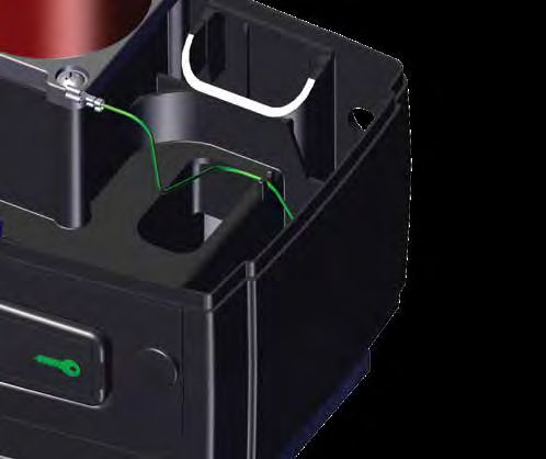
page 40 www.centsys.comRoute the Earth Harness up to Cable
Management
the left and place it into the Cable Clip
Management Clip as shown in
Figure 67.
The Earth Harness will
need to be routed under
the battery at a later
stage.
Earth
Harness
Gearbox
FIGURE 67
7.9.2.2. Placing the Spring Washers and Lock Nuts
Only add the Spring Washers and Lock Nuts once the Rack has been installed
and the operator height is correct.
Place one Spring Washer and one Lock Nut onto each of the Mounting Bolts. Tighten all of
the Lock Nuts with a 17mm socket to secure the Earth Harness and the height of the D5
SMART firmly in position.
Lock Nut
Spring
Washer
Earth Harness
FIGURE 68
page 41 www.centsys.comSECTION 7 OPERATOR INSTALLATION
7.10. Re-assembling the D5 SMART
7.10.1. Override Sensor
If the Override Sensor has previously been removed, take note of how it is
placed back into position correctly, before continuing with the installation.
Override
Sensor A
Override
Sensor
Locating Slot
B
Note the
orientation of the Push the Override Sensor "A" firmly
Override Sensor until it seats onto the gearbox "B"
FIGURE 69. OVERRIDE SENSOR
7.10.2. Routing the Override Sensor Harness
It is important to ensure that the harness for the Override Sensor is routed
through the correct location when inserting the Lower Battery Tray back into
position.
Groove for
The Override Sensor harness is Harnesses
routed directly in front of the electric
motor.
There is a groove located in the
middle of the Lower Battery Tray, on
the motor's side. The harness needs
to be routed between the electric
motor and the Lower Battery Tray
here as the Lower Battery Tray is
placed back into position. Lower
Battery Tray
FIGURE 70
page 42 www.centsys.comSECTION 7 OPERATOR INSTALLATION
7.10.3. Placing the Lower Battery Tray and Charger back into Position
Ensure that the Camlock is in the "unlocked" position and that the Release
Handle is partially open.
Place the Lower Battery Tray into position. Whilst doing this, route the cabling and
harnesses through. A click from both sides will be heard if the tray is fitted correctly.
Locked
Ensure that the Cam Driven
Slide is in the correct
position before placing the
Lower Battery Tray back into
the Gearbox. Cam Driven Slide
i.e. Push it to the left.
Refer to Section 7.4 - Unlocked
"Preparing the D5 SMART
for Installation" for further
information on locked and
unlocked positions
Cam Driven Slide
Note the position of the
Override Sensor Harness.
Gearbox
Groove for
Harnesses Override Sensor
Harness
Earth Harness
Lower
Battery Tray
Cam Driven
Slide
FIGURE 71. LOWER BATTERY TRAY PLACEMENT
page 43 www.centsys.comSECTION 7 OPERATOR INSTALLATION
Electric
Motor
Slots
Place the Charger back into position
by aligning the three feet at the Lower
Battery
bottom of the Charger with the three Tray
slots found on top of the Lower
Battery Tray. Charger
Place the studs of the Charger into
the three holes on the Lower Battery
Tray. Firmly press the Charger down, Lower
Battery
and push it toward the Electric Tray
Motor, sliding it along the slots.
Stud
Slot
FIGURE 72. CHARGER PLACEMENT
7.10.4. Placing the Control Card back into Position
Control Card
Support Tray
Ridge
Tilt the control card and align the
Clip Wider gap
wider gap with the clips shown in
Figure 73. Ridge
Left Tab
Control
Card
FIGURE 73
Left Tab
Once aligned, hinge the Control Card
under the tab's lip, and firmly press Right Tab
downward on both sides in front of
the Control Card.
This will engage the Control Card
into the hinges at the front of the Control Card
Control Card Support Tray.
A click from both sides will be heard
if this is done correctly. Control Card
Support Tray
FIGURE 74
page 44 www.centsys.com7.10.5. Reconnecting the Harnesses to the Control Card and Charger
Reconnect the Motor Wires at
Position "A" and the Override
Harness at Point "B" on the Control
card.
The black motor wire
is connected on the
far Left of the Control
Card, and the blue on A B
the immediate right of
the black.
A
B
FIGURE 75
Reconnect the Charger Harness
to the point from which it was C
disconnected earlier, either at
Position "C" or at Position "D".
If the connection is made Harness
at Point "C", note that
there are two connector
D
blocks that need to be Charger
reconnected to the
Control Card.
Utilise the Cable Retainers
at the bottom of the
FIGURE 76
accessory storage to neaten
up the wiring, and the
overall installation.
Connect the Earth Harness into the
Charger
right-hand side of the Charger at
Point "E".
Earth
Harness E
FIGURE 77
page 45 www.centsys.comSECTION 8 COMPLETING THE INSTALLATION
8. Completing the Installation
8.1. Fitting the Batteries
Push the left tab Swing the upper
backwards assembly forward
Gently push the left tab behind the
Control Card backwards. This will
allow the entire upper assembly to
hinge forward.
FIGURE 78
Place a Battery into the designated
area found on top of the Lower
Battery
Battery Tray on the left. Route the
Power and Signal cables between
the right Battery compartment and
the Electric Motor then place the
remaining Battery in it's designated
area on the right.
Note the orientation of
the two Batteries. Ensure
that the Battery Terminals
always face the direction of Lower
the Charger. Battery Battery Tray
FIGURE 79
Take extra care not to
pinch the Earth Harness
when placing the Battery Battery Battery
on the right. The Earth
Harness must be routed
under this Battery and
out the gap found in front
of the Battery once in
position.
Swing the upper assembly back into
position over the batteries.
A click should be heard if this is done
correctly.
Failure to properly click
the control card and
upper assembly into
place will result in erratic Lower Earth
Battery Tray Harness
behavior of the gate
motor. FIGURE 80
page 46 www.centsys.comSECTION 8 COMPLETING THE INSTALLATION
Battery
Harness
Connect both batteries up with the
supplied harness, and ensure that it
is connected to the left side of the
Charger.
Route the accessory cables around
the back of the Charger and through
the cable retainers found in front of
the Control Card.
Charger
FIGURE 81
8.2. Accessory Installation and Storage
There are dedicated trays below the D5 SMART Control Card to conveniently install and
store any accessories connected to the Operator.
Control Right
Card Door
Opening the two retaining doors, Left
Door
reveal the storage space for
accessory products, such as the
G-ULTRA, or External Receivers.
FIGURE 82
Accessory
Retaining
Door
Wire the accessory device to the
operator, place it into the space
provided, and close the door.
G-ULTRA
FIGURE 83
page 47 www.centsys.comSECTION 8 COMPLETING THE INSTALLATION
8.3. Wiring the Control Card on its Default Settings
The D5 SMART Control Card's Input / Output terminals are defaulted with the following
configuration;
Control Card Control Card
Default Setting Default Setting
Terminal Terminal
I/O1 Trigger (TRG) I/O4 Gate Status
I/O2 Pedestrian (PED) I/O5 Free-exit (FRX)
I/O3 Infrared Beam Close (IRBC) I/O6 Safe Common
TABLE 2
8.3.1. Closing Infrared Beam Wiring (I5 Infrared Beams)
D5 SMART
Control Card
IRB Receiver
12V/24V -
12V/24V +
COM
NC
NC
COM
NO
IRB Transmitter
12V/24V +
12V/24V -
Please contact Centurion
Systems (Pty) Ltd for directions
on wiring Infrared Beams in an
opening configuration.
FIGURE 84
page 48 www.centsys.comSECTION 8 COMPLETING THE INSTALLATION
8.3.2. Closing Infrared Beam Wiring (Photon Infrared Beams)
D5 SMART
Control Card
IRB
Receiver
12V/24V -
12V/24V +
COM
NC
NC
COM
NO
Wireless IRB
Transmitter
Please contact Centurion
Systems (Pty) Ltd for directions
on wiring Infrared Beams in an
opening configuration.
FIGURE 85
page 49 www.centsys.comSECTION 8 COMPLETING THE INSTALLATION
8.3.3. External Radio Receiver and Loop Detector Wiring
D5 SMART
Control Card
Free-exit Loop
12V/24V -
12V/24V +
COM
NC
NO
COM
NO
Loop Detector
External Radio
Receiver
12V/24V -
12V/24V +
COM
NC
NO
COM
NO
FIGURE 86
page 50 www.centsys.com8.3.4. Earth Spike Installation
For further surge protection, an Earth Spike1 can be installed. Route the earth cable
from the Earth Spike around to the back of the D5 SMART, and under the Gearbox by
the Cable Shield. Connect it to the Mounting Bolt on the right of the Gearbox where the
Charger Earth is located by means of a Ring Lug.
See Section 7.9.2.1. - "Placing and Routing the Earth Harness".
Utilise the Cable Management Clip to keep the wiring neat and out of the way.
Gearbox
Cable Management
Clip
Earth
Spike
Cable
Earth Return Cable Shield
FIGURE 87
1. Not supplied with the D5 SMART.
page 51 www.centsys.comSECTION 8 COMPLETING THE INSTALLATION
8.3.5. G-ULTRA to D5 SMART Wiring
G-ULTRA RELAY 1 RELAY 2
GND IO1 IO2 IO3 IO4 NO COM NC NO COM NC + VDC -
TRG
PED
FRX
STATUS
+12V
COM
D5 SMART
Control Card
FIGURE 88
8.4. Commissioning the System
1. Scan the QR Code in
Figure 89. Download on the
App Store
2. Select the App Store
Minimum Requirements:
applicable to the
• BLE-enabled mobile phone
operating system being
• iPhone 5 and above
used, either Apple iStore • iOS8
or Android Google Play
Get it on
Store.
3. Download and install the Minimum Requirements:
application.
• BLE-enabled mobile phone
• Android 4.4.2. (KitKat)
FIGURE 89
Alternatively, go directly to the app store of the operating system being used, and search
for the app "MyCentsys Pro". Download and install the application onto the smartphone.
1. Once installed, open the application.
2. From the list of gate operators, select the operator that is applicable to this
installation.
3. Connect to the relevant gate operator.
4. Use the app by following the prompts to configure the D5 SMART.
page 52 www.centsys.comYou can also read