Connecting the Clean Air Enterprise electric Air Filter to the building control system Operating instructions
←
→
Page content transcription
If your browser does not render page correctly, please read the page content below
Version 3 May 2018

       Connecting the Clean Air Enterprise
      electric Air Filter to the building control
          system Operating instructions

                                   Firmware - Version:                    V1.00, x. x.201x

                                   Document version:                          3 May 2018

Clean Air Enterprise connection electrostatic precipitator systemPage 1/ 12                            RFO / MAB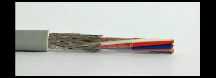
Version 3 May 2018

1 Table of contents

1  Table of contents ........................................................................................................................ 2
2  Description / Application ............................................................................................................. 3
 2.1 Mains connection L, N, PE ................................................................................................... 4
   2.1.1 Mains connection material .............................................................................................. 4
 2.2 Connection of the electrostatic precipitator system to the building management system .... 5
   2.2.1 Input signal 0-10V Default value of air volume (GLS EFA)à ......................................... 5
   2.2.2 Floating contacts (EFA GLS)à ...................................................................................... 7
3 Installations on the monobloc ..................................................................................................... 8
 3.1 Plant overview ...................................................................................................................... 8
 3.2 Housing assembly of the control unit .................................................................................... 8
 3.3 Door switch and key switch connection ................................................................................ 9
 3.4 Cable entry through monoblock .......................................................................................... 10
4 Technical Specification Electrostatic Precipitator Electronics ................................................... 11
5 Change log Document .............................................................................................................. 12

Clean Air Enterprise connection electrostatic precipitator systemPage 2/ 12                                                       RFO / MAB
Version 3 May 2018

2 Description / Application
The Clean Air Enterprise electrostatic precipitator cleans the air of a building efficiently and
thoroughly. The required air volume is determined by the building management system. The
electrostatic precipitator system should fit into an existing HVAC infrastructure. These instructions
are intended to enable specialist partners to integrate the electrostatic precipitator system and are
aimed at specialist personnel. Work on the systems may only be carried out by trained specialists.

               GLS                                                                         EFA
        Gebäudeleitsystem                                                           Elektrofilteranlage
         mit SPS bauseits                                                        Clean Air Enterprise AG

    schwarzer Pfeil:                 Netzanschluss 230V LNPE, Netzspannung

    blauer Pfeil:                    Kommunikation SPS - Master, SELV Spannung
    Abbildung 1: Übersicht

Abbreviations:               GLSBuilding Management System           (light                           green)
                             EFAElectrostatic filter system (light blue)

Clean Air Enterprise connection electrostatic precipitator systemPage 3/ 12                         RFO / MAB
Version 3 May 2018
2.1 Mains connection L, N, PE
The power supply for smaller systems up to 1kW connected load of the filter system is 1 -phase with
230V alternating current via a separate, on-site fuse FILS13C. The cable required for this is
3x1.5mm2. Earth, neutral and phase are connected.
Stecker CN1 auf Steuerung CALS
Nummer Name Farbe Gruppe Signal-Beschreibung
1 PE gelb-grün Schutzleiter PE
Netz-
2 N blau Neutralleiter
Anschluss
3 L braun Phase 230VAC
Abbildung 2: Anschlussbelegung CN1 Netzanschluss 1 phasig
The power requirement depends on the number of electrostatic precipitators, i.e. the size of the
system. As a project planning value, 12W per 1000m3/h can be calculated.
Systems up to approx. 100'000m3/h can be designed single-phase.
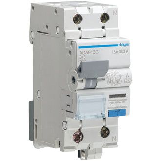
2.1.1 Material mains connection
Suggested fault current circuit breaker (on-site, not included in the scope of delivery)
Type: Hager
ADS913C FI/LS switch
1P+N6kA C13A 30mA 2TE
E-No: 804129264
Caution: In the case of a powerful sub-distribution with a high short-circuit current, the back-up
fuse must be designed according to the breaking capacity of the RCD/LS. Consult
your electrical planner who planned the distribution.
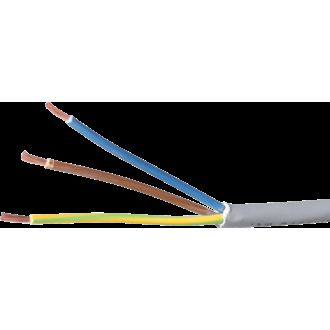
Suggested connection cable (on-site, not included in the scope of delivery)
Type: Apparatus cable
3x1,5mm² LNPE
halogen-free, light grey
E-No: 114015325
Tips: The PLC can switch the supply of the electrostatic precipitator system on and off via a
contactor. In addition, the mains supply can be routed via an electrostatic precipitator main
switch (provided by the customer).
Clean Air Enterprise connection electrostatic precipitator systemPage 4/ 12 RFO / MABVersion 3 May 2018
2.2 Connection of the electrostatic filter system to the building management
system
The electrical connection between the building management system and the electrostatic precipitator
system is made with safety extra-low voltage SELV, i.e. on the side of the building management
system as well as on the side of the electrostatic precipitator system, the units are supplied with non-
hazardous safety extra-low voltage.
2.2.1 Input signal 0-10V Preset value of the air volume (GLS EFA)à
The control with the building management system is done via PLC signals. The preset value for the
performance of the electrostatic precipitator system is necessary via a 1-10V signal from the PLC to
the electrostatic precipitator system. The signal is galvanically separated from the mains voltage
both on the PLC side and on the side of the electrostatic precipitator.
Luftstrom % vs Eingangsspannung V
100 % Luftstrom %
90 %
80 %
70 %
60 %
50 %
40 %
30 %
20 %
10 %
0%
0V 1V 2V 3V 4V 5V 6V 7V 8V 9V 10 V
Abbildung 3: Eingangssignal 0-10V
For the electrostatic precipitator to switch on, the input signal must be greater than 1.0V for at least
5 seconds. For the electrostatic precipitator to switch off, the input signal must be below 0.7V for at
least 5 seconds.
An input signal of 10V indicates to the electrostatic precipitator the maximum air flow that the unit
can handle. Depending on the input voltage applied, the electrostatic precipitator optimises the
operating point for maximum cleaning effect and optimum energy consumption.
For this input signal, the analogue output of the GLS PLC must be connected to the signal ASIG and
the reference ground AGND.
Clean Air Enterprise connection electrostatic precipitator systemPage 5/ 12 RFO / MABVersion 3 May 2018
Stecker CN5 auf Steuerung CALS
Nummer Name Farbe Gruppe Signal-Beschreibung 4er & U72-Farbe
1 L12V weiss RS485 Speisung, 12V, 500mA max. (für FOX)
(ws)
a - weiss
2 LGND braun BUS Masse, 0V
(bn)
b - grün
3
grün RS485 RxTx+ reserviert für
3 RXTX+ c - türkis
(gn) Datenkommunikation
gelb RS485 RxTx- reserviert für
4 RXTX- d - violett
(gb) Datenkommunikation
grau Reinigung Signal
5 CL Signal a - weiss
(gu) zu Arbeitskontakt von E-Filter
rosa Reinigung Signal
6 CL Reinigung b - orange
(rs) zu Arbeitskontakt von E-Filter
2
blau Fehler Signal
7 EO Signal c - türkis
(bl) an Arbeitskontakt von E-Filter
rot Fehler Signal
8 EO Fehler d - violett
(rt) an Arbeitskontakt von E-Filter
9 AGND schwarz Signal Masse, 0V für Analogeingang a - weiss
(sz)
1
violett Analogsignal: Ansteuerung 0-10V von
10 ASIG Fan-Speed b - blau
(vi) Gebäudesteuerung zu E-Filter
Schirm Schirm-Anschluss im Schaltschrank an Erdung Schirm
Abbildung 4: Anschlussbelegung CN5 SPS-Interface zu Gebäudeleitsystem
Suggested control cable (on-site, not included in the scope of delivery)
Type: Control cable
10 x 0.5mm² shielded
halogen-free, grey
Core colours according to DIN 47100
e.g.: Supplier ISOMET: 4713.710 ISOCOL-
ECO C 10 x 0.5 mm² grey DIN 47100
halogen-free
Figure 4 also shows the alternative assignment of a U 72-3 x 4 cable.
The control cable must not exceed the maximum outer diameter of 10 mm, otherwise it will not fit
into the intended attachment on the unit.
Note: If the shield cannot be connected in the control cabinet of the PLC, it is possible to connect
the shield to the Faston connection "shield". However, the one-sided connection in the
control cabinet is preferable.
Attention: The shield may only be connected on one side of the cable!
Clean Air Enterprise connection electrostatic precipitator systemPage 6/ 12 RFO / MABVersion 3 May 2018
2.2.2 Floating contacts (EFA GLS)à
The control unit of the electrostatic precipitator system has two potential-free relay outputs that
indicate the status of the electrostatic precipitator system to the building management system. One
signal indicates whether the electrostatic precipitator system is working properly. This is the signal
EO.
The table below indicates which signal combinations are possible:
Cleaning Error/OK
Fall Bedeutung
CL EO
1 inaktiv inaktiv Anlage ausser Betrieb oder kein Strom oder hat Störung, Fehler, Defekt
2 aktiv aktiv Anlage benötigt Reinigung, läuft aber einwandfrei
3 inaktiv aktiv Anlage in Betrieb und arbeitet einwandfrei
4 aktiv inaktiv Anlage aktiv, Tür-/Schlüsselschalter offen oder Anlage wartet auf 1. Start
Abbildung 5: Bedeutung der Rückmeldesignale
Signal CL is active: Relay 1 pulls in LD1 lights up
Signal CL is inactive: Relay 1 drops out LD1 dark
Signal EO is active = OK: Relay 2 pulls in LD2 lit, LD3 dark
Signal EO is inactive = Error: Relay 2 drops out LD3 lights up, LD2 dark
The PLC of the building management system can detect whether the electrostatic precipitator system
has power. When the system is started, case 4 is output for at least 5 seconds. If a preset value
greater than 1V is then applied to the analogue input, the CL signal becomes inactive (case 3). If the
door is open or the key switch for the high voltage is open, case 4 remains active despite the
analogue voltage being applied.
If the unit needs cleaning (case 2), case 2 is displayed after 5 seconds.
The PLC can use this logic to control all lines to and from the electrostatic precipitator at start-up,
especially if the PLC can also switch the voltage supply to the electrostatic precipitator.
Attention: A maximum of 24V/1A safety extra-low voltage may flow through the contacts and
under no circumstances mains voltage!
Clean Air Enterprise connection electrostatic precipitator systemPage 7/ 12 RFO / MABVersion 3 May 2018
3 Installations on the monobloc
The electrostatic precipitators and the blue electrostatic precipitator nodes are installed inside the
monoblock. The control electronics (master) with the power supply unit is installed outside the
monoblock. A control line leads into the monoblock. This line leads to the first electrostatic
precipitator and then on from electrostatic precipitator to electrostatic precipitator.
The connecting cables between the master and the first electrostatic precipitator and between the
electrostatic precipitators are supplied.
3.1 Plant overview
Türschalter
Netzspannung 230V
Clean Air Enterprise Innenraum Monoblock
Steuerung
Elektrofilteranlage Durchführung
Elektrofilternode 1 Elektrofilternode 2 … Elektrofilternode 6
Gebäudeleitsystem
int. Schlüsselschalter
Elektrofilter 1 Elektrofilter 2 … Elektrofilter 6
Abbildung 6: Übersicht Elektrofilteranlage am bauseitigen Monoblock
Connect the mains voltage and the building management system as in 2.1, 2.2 above. The safety
door switch (see 3.3) for switching off the voltage supply to the electrostatic precipitator high-voltage
generation must be installed in such a way that it is impossible to hold the door open without being
able to operate the switch. Several door switches can also be connected in series. The key switch
is used to alternatively switch off the high voltage.
3.2 Housing assembly of the control unit
The fixing template of the control box with the drilling points for the suspension screws.
Montage-Schablone Steuerungsgehäuse
Mass-Angaben in mm
13 min Einhängebereich
Einhäng-
Schrauben- beigelegte
Detail
4x M 1:1 Einhängeschraube
Verschraubung
98 min
< 4.7 mm
des Deckels
Wand
Schraube
4x BN 1878
5.5 ... 8.9 mm
ST 3,5 x 25
~ 7 mm Art.Nr: 1394428
S-Link Ausgang
141 min 278 141 min
Speisung Linie - B
Ausgang Ausgang
Bereich Bereich
für 138 4x
Einhänge-
für
320 schraube
Kabel Kabel
Speisung ~ 230 VAC Linie - A
Eingang Ausgang
B
Detail: B 4,8
M 2:1
Türschalter oder
S-Link Eingang
11
Gebäudeleitsystem 107 min
9
Schlüsselschalter
100 min 360 100 min
Version: 2017-08-16 10 min Art.Nr.: V109.025
Clean Air Enterprise connection electrostatic precipitator systemPage 8/ 12 RFO / MABVersion 3 May 2018
Enclosed are the self-tapping sheet metal screws as suspension screws. Alternatively, the box can
also be mounted on two vertical support rails. The support rails are available as accessories on
request.
3.3 Door switch and key switch connection
The door switch and the key switch are operated with safety extra-low voltage and are interrogated
by the control unit. The key switch is already connected to plug CN4 and is already supplied with the
master.
Stecker CN4 auf Steuerung CALS
Nummer Name Farbe Gruppe Signal-Beschreibung
1 Key weiss Schlüsselschalter Kabel
Security
2 Key weiss Schlüsselschalter Kabel
Abbildung 7: Anschlussbelegung CN4 Security Key
A safety door switch must be used for this system. A
recommended door switch is one from OMRON's D4NS series.
For example, D4NS-4AF or D4NS-4BF could be used together
with a key from OMRON's D4DS series. A pair of NC contacts
from the D4NS is connected to the CN11 connector on the
control unit. For the cable connection, a suitable cable gland with
a maximum thread length of 9mm is required on the door switch
side. For the D4NS-4AF or D4NS-4BF door switch, it is an M20
cable gland.
The door switch is connected to plug CN11 during installation. It ensures that no dangerous high
voltage can be applied to the filters when the door is open.
Stecker CN11 auf Steuerung CALS
Nummer Name Farbe Gruppe Signal-Beschreibung
1 Door weiss Türschalter Kabel
Security
2 Door braun Türschalter Kabel
Abbildung 8: Anschlussbelegung CN11 Security Door
Attention: It is essential that the safety circuits Door and Key are closed so that the electrostatic
precipitator system runs!
If the safety circuits are not closed, the REL3 relay drops out. For the 24V power supply to be active,
the software must switch on relay REL3 and the safety circuits must be closed. The LED LD4 lights
up when the REL3 relay is active.
The safety circuits are linked in hardware with the logic signal of the microcontroller.
Clean Air Enterprise connection electrostatic precipitator systemPage 9/ 12 RFO / MABVersion 3 May 2018
3.4 Cable feed-through through monoblock
The control cable that connects the control electronics with the first electrostatic precipitator node
inside the monoblock must be led through the monoblock housing. A special cable bushing is used
for this purpose, through which a cable ready made up with plugs can be passed.
For this cable gland, it is necessary to make a 32 hole through the
monobloc housing and then insert the cable through the slotted seal
and the cable gland. The cable gland snaps into place and is secured
from the inside with the union nut. The cable gland is absolutely
airtight.
The cable gland is included in the scope of delivery of the unit.
If necessary, a slightly larger hole must be drilled on the inside of thick housings so that the union
nut can be fitted.
The cable is connected to the connector "CN6 to Nodes".
Clean Air Enterprise connection electrostatic precipitator systemPage 10/ 12 RFO / MABVersion 3 May 2018
4 Technical specification electrostatic precipitator electronics
Mains connection
Power supply: 230VAC 50/60Hz single phase
Power consumption: 5W plus 40W per filter
Hedging: FI/LS 13C
Signal input for air volume (fan speed)
Signal voltage: 1-10V Input impedance approx. 100kOhm
Potential free contacts
Potential-free signal contacts: Relay REL1 and REL2: 24V/1A max. SELV
General specifications
Maximum number of filter nodes 6 per line server (Attachment 21'000m3/h)
with
Maximum number of LineServers: 6 per master, total 36 nodes (Attachment 126'000m3/h)
with
Clean Air Enterprise connection electrostatic precipitator systemPage 11/ 12 RFO / MABVersion 3 May 2018
5 Change log document
Date: Visa: Description:
13 March 2017 RFO Initial version
26 June 2017 MAB Corrections, adapted graphics, cable U72
16 August 2017 MAB Template for housing assembly
3 May 2018 MAB Control cable outer diameter
Clean Air Enterprise connection electrostatic precipitator systemPage 12/ 12 RFO / MABYou can also read