Concrete cutting An operAtor's guide for
←
→
Page content transcription
If your browser does not render page correctly, please read the page content below
An operator’s guide for
concrete cutting

The purpose of this publication is to let you know how important you are
to this company, what is expected of you and to give you basic information on
the tasks you may be performing .

      The major difference between the successful professional cutter and the
one destined to go out of business is the skill and abilities of its' field operators-
You. You are the most important part of this business and as an operator you
affect two thirds of the costs of running it. Mistakes made in cutting operations,
accidents and attitude can put profit on the bottom line or the company out of
business.

       We know that you want to learn, improve and make yourself more valuable
to the company, your family and yourself. To be a better cutter you should know
the traits of a good field operator. Think about these traits, how you compare, and
how you can improve on those which you are weak.

                 For more information on sawing and drilling
                 check out our "How To" videos available free
                   on our website: dynatech-diamond.com

                              DI A M ONDS A T W OR K
CONTENTS:
TRAITS OF A GOOD OPERATOR ...............................................1-2
HOW DOES AN OPERATOR EFFECT PROFIT ...............................3
CORE DRILLING................................................................................4
FLAT SAWING....................................................................................5
WALL SAWING...................................................................................6
WIRE SAWING ...................................................................................7
CHAIN SAWING .................................................................................8
HOW DIAMOND CUTTING TOOLS WORK.......................................9
FACTORS THAT EFFECT PERFORMANCE...................................10
SPEEDS, FEEDS AND NOMENCLATURE......................................11
TROUBLE SHOOTING DIAMOND BLADES..............................12-14
TROUBLE SHOOTING DIAMOND CORE BITS .............................15
DIAMOND BOND PROBLEMS.........................................................16
EQUIPMENT ANCHORING..............................................................17
MECHANICAL ANCHOR GUIDE.....................................................18
ADHESIVE ANCHOR GUIDE ..........................................................19
CARBIDE BITS ................................................................................20
LADDER SAFETY ......................................................................21-22
CORDS & POWER ..........................................................................23
HOW TO SELECT A GENERATOR.................................................24
SAFETY SYMBOLS..........................................................................25
CONVERSION CHART.....................................................................26
AVERAGE WEIGHTS OF MATERIALS..........................................27THE TRAITS OF A GOOD OPERATOR
1. GOOD COMMUNICATOR - is able to quickly and clearly
have the customer understand what he can and cannot do.
A good communicator must be able to describe situations
and problems found in the field to an office supervisor or to
others at the office.
2. HIGH DEGREE OF COMMON SENSE - This is the ability to
know what to do and most importantly what not to do in a situ-
ation. A good example of common sense is not to run an electric
core rig while standing in 10 inches of water.
3. POSITIVE ATTITUDE - Maintaining a “Can Do” positive
attitude is not only a reflection of the operators ability to
get the job done but tells the customer that it will be done
right. A positive attitude means keeping your problems, be
they personal or business, to yourself. It is the foundation of
being a true professional.
You're
late !
4. DISCIPLINED - Being on time, sticking to the schedule and do-
ing what has to be done to complete the job requires discipline.
Discipline and a positive attitude go hand in hand.
5. NEAT - You are not just a cutter. You are a representative of
your company. If you have holes in your pants, a dirty shirt, are
operating dirty equipment or leave a dirty job site after cutting,
it tells the customer that this is the way your company runs it’s
business. We all know that this is not true !
16. DETAIL ORIENTED - Keeping accurate records of the footage
cut and the time on the job is as important as your paycheck.
Guessing at what you have done can mean a loss of profit, the
overcharging of the customer and eventually the loss of your
job. Being detail oriented applies to all record keeping - footage
cut , holes drilled, time on the job, maintenance of equipment
and what spec diamond tool was used on the job.
7. ABILITY to ADAPT, IMPROVISE AND OVERCOME - is the mark
of a true professional. It means that you are still able to do the job even
though it is not what you thought it was supposed to be. It means find-
ing a way to drill that 24” hole vertically when you thought it was on the
deck. It means fixing the equipment and getting the job done rather
than quitting and going back to the shop.
You have to
change that bit !
8. STEADY PERSONALITY - This does not mean that
you are always the good guy but that you are not subject
to temper tantrums and wild swings in moods and per-
sonality. It means that you can be counted on to get the
job done under almost any circumstances without losing
your cool.
9. DESIRE TO LEARN AND IMPROVE - The more
your learn, the more valuable you are to the company,
to your family and to yourself. With each new acquired
skill comes a higher degree of professionalism which will
almost always find it’s way into your paycheck.
10. UNDERSTANDS THE NEED FOR PROFIT - This is the
most important trait. As an operator, you are delivering a service
for a profit. Without profit there would be no company. Profit is
what allows your company to buy more equipment and to pay
you on a regular basis even though business may be slow. Profit
allows your company to advertise it’s services, to experiment
with new equipment and techniques and to grow it’s business.
Profit is the reason you are working. You as an operator have a
great effect on it.
2HOW DO YOU EFFECT PROFIT ?
Unless you are a socialist, profit is not a dirty word. Profit is the reason
you are here and profit is directly controlled by costs. You effect two
thirds of the costs of running this company. Here are four areas where
you can have a positive or negative effect on costs:
SAFETY - We can never over emphasize the need for safety, not be-
cause accidents and injuries cut profits and raise costs, but because
they effect our most valuable asset - You. Hard hats, steel toed shoes,
eye protection and back braces only work if they are used.
TIME - 1/3 of all costs are for your time. Taking too long
or goofing off on the job cuts profit and irritates the
customer.
TOOLS - Diamond bits and blades can be very expensive. Using a
bit or blade with the wrong specification wastes money. Abusing
a bit or blade such as hitting it with a hammer to remove it will not
be tolerated. Remember a 1% decrease in diamond cutting tool
costs can put 10% profit on the bottom line jst as a 1% increase
can take off 10% and jeopardize your job.
EQUIPMENT- Not repairing or failing to bring needed repairs
to attention wastes both time and money. Using equipment
that is not up to snuff is like diving into a swimming pool
without knowing if there is any water in it.
I wonder whats going
on down there ?
EDUCATION - You are by nature equipment oriented, NOT process
oriented. This means that you know how to operate the machinery
but not what the diamond cutting tool is doing. Understandingthe
process increases your performance and makes you more valuable.
3UNDERSTAND NOT ONLY WHAT YOU DO BUT HOW YOU DO IT !
CORE DRILLING
As there are more variables in core drilling than in any other type of cutting, be-
ing competent in core drilling is the foundation of a good cutter.
Factors that affect bit performance and company profit:
Speed (RPM) -If the speed is too high the bit will polish. If the speed is too low
the job will take too long.
Power is necessary to maintain the proper cutting speed. Efficient cutting means
keeping the bit at the right speed.
Water - Not too little and not too much-The right amount
removes slurry and keeps the cut clean.
Aggregate - You can't see it until you're done, but a good driller can
feel the right speed and pressure to cut varying types.
Steel - slows the cutting process. Maintaining drill motor speed is important.
DON'T PUSH THE BIT TOO HARD !- MAINTAIN SPEED !
Bond Specs - Too hard and it takes too long. Too soft and it costs too much.
Proper Alignment - is necessary for good bit life. This means the rig must
be properly anchored. A rig can be anchored with concrete anchors,
vacuum or a post jack.
STANDING ON THE RIG IS DANGEROUS AND NOT ACCEPTABLE !
Core Rig Maintenance -performance, speed and bit life will mean little if
your rig has bad shims, bearings and hold down devices.
RECOMMENDED HORSE POWER RECOMMENDED
BY BIT DIAMETER CORE DRILLING SPEEDS
Bit Min. Min.
Diameter AMPS HP GPM Bit Minimum IDEAL Maximum
1"-4" 13 1-2 - Diameter RPM RPM RPM
15 2 - 1" 2400 3200 4000
5"
2" 1200 1600 2000
6" 15 2 - 3" 800 1050 1300
7" 15 2-3 - 4" 600 800 1000
8" 15 2-3 - 5" 475 640 800
18 2-3 - 6" 400 530 665
10"
7" 340 450 600
12" 18 3 - 8" 300 400 500
14" 20 3 - 10" 240 320 400
16" * - 12" 200 265 330
* 8-10 @ 1500 PSI 14" 170 225 285
18"
16" 150 200 250
20" * 8-10 @ 1500 PSI 18" 130 175 220
24" - 8-10 @ 1500 PSI 20" 120 160 200
26" - 8-10 @ 1500 PSI 24" 100 130 165
- 12-15 @ 2000 PSI 26" 90 125 150
30"
30" 80 105 130
32" - 12-15 @ 2000 PSI 32" 75 100 125
34" - 12-15 @ 2000 PSI 34" 70 95 120
36" - 15-20 @ 2500 PSI 36" 65 85 110
- 15-20 @ 2500 PSI 40" 60 80 100
40"
42" 55 75 95
42" - 15-20 @ 2500 PSI
* Not recommended for 120 Volt Use 220V 0r Hi-Cycle machine
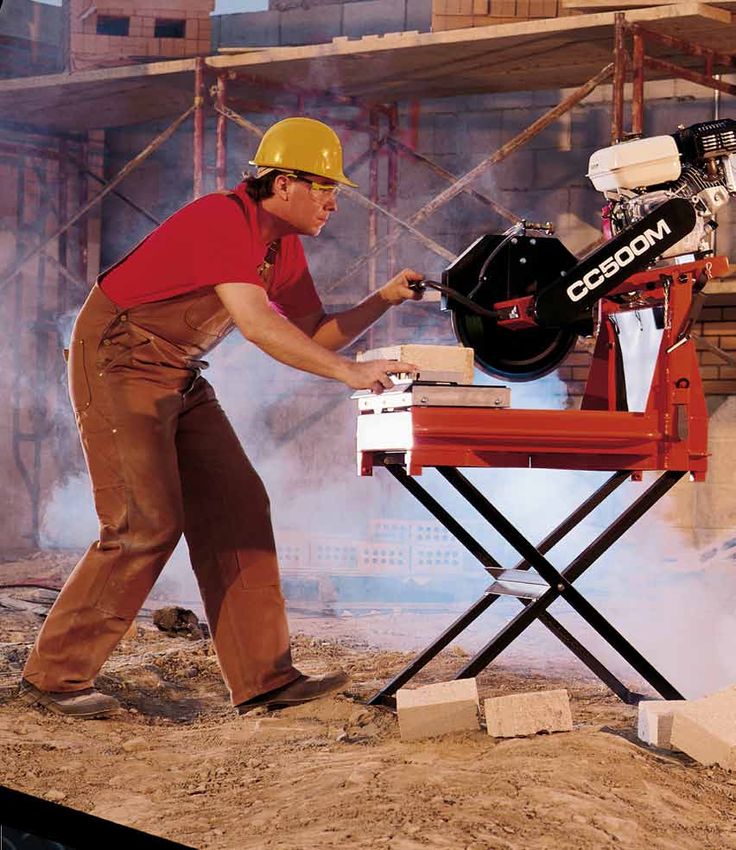
4FLAT SAWING
Successful flat sawing is a combination of blade selection,
blade speed and common sense.
Pay Attention ! -The saw does not follow the
cut itself- you have to guide it ! - Stay with the
controls.
Water -is the blade's life and death. Don't be sparing
with it . When road sawing keep the hose out of the
traffic lane. Never gravity feed the water to the cut.
Always step cut - Make a 1" cut as your guide
cut- Never cut full depth on the first pass.
Blade Speed -Always match the RPM of the saw
to the diameter of the blade . Running a bladeat
higher than recommended speed is dangerous. At
worst the blade could fly apart and at best it
reduces cutting effi- ciency. The maximum cut-
ting efficiency of a blade is at approximately 12,000
SFPM (surface feet per minuite) or 150 Miles Per Hour.
PRODUCTIVITY IS NEVER INCREASED BY
INCREASING BLADE SPEED !
Listen to the engine- You'll be able to tell when
a blade is bouncing, the belts are slapping (loose) RECOMMENDED
and when the blade is lifting itself out of the cut. BLADE RPM & MAXIMUM DEPTH OF CUT
Blade Operating Blade Maximum
Diameter RPM Collar Depth of Cut
14" 2900 4-1/2" 4-3/4"
16" 2600 4-1/2" 5-3/4"
18" 2600 4-1/2" 6-3/4"
20" 2450 4-1/2" 7-3/4"
24" 1950 4-1/2" 9-3/4"
26" 1950 4-1/2" 10-3/4"
30" 1650 6" 12"
36" 1400 6" 15"
42" 1050 6" 18"
48" 850 8" 20"
54" 775 8" 23"
5WALL SAWING
Accuracy is the key to profitable wall sawing.
Track Setting- Accurate track setting is critical. A little to
the left.
Right Blade - The bonds used in wall saw blades are made not
only for specific materials but different types of saws as well.
Make sure you have the right blade for the job.
Speed - Wall saws in general have less horsepower than
other types of saws. Maintaining the right speed
means paying close attention to the saw- you'll be able to
tell when cutting concrete or rebar. Make sure the blade
is running at the correct RPM. Don't over speed the blade.
Water - is always important, especially when you are on a wall.
Keep the pressure up !
Step cut- Don't over cut ! - Proper step cutting
NEXT ! minimizes the cost per inch foot of cut and
maximizes blade life. Step cutting increases the
horsepower available to the blade and allows i n-
creased water flushing.
Safety- Don't cut the branch you are standing on and make sure
it is properly secured !
* Plan your cuts so you and your equipment are not on a piece
when it breaks loose.
* Insure that the blade is running in the proper direction.
* Make sure the blade is in good condition with no
cracks, nicks or flaws. RECOMMENDED
* Use only steel centered wet cutting diamond blades. BLADE RPM & MAXIMUM DEPTH OF CUT
* Do not use high speed steel blades, carbide tipped
blades or abrasive blades. Blade Operating Blade Maximum
* Always keep the blade guard in place and in good Diameter RPM Collar Depth of Cut
condition. 14" 1500 5" 4-1/2"
* Always keep all parts of your body away from the 16" 1500 5" 5-1/2"
blade. 18" 1500 5" 6-1/2"
* Avoid getting in a direct line with the blade. 20" 1500 5" 7-1/2"
* Make sure the track is securely anchored and track 24" 1450 5" 9-1/2"
stops are installed. 26" 1450 5" 10-1/2"
* Insure there are no electric, water or gas lines in the 30" 1400 5" 12-1/2"
area you are cutting. 36" 1300 5" 15-1/2"
* Do not operate the saw near combustible materials 42" 950 5" 18-1/2"
or fumes. 48" 850 5" 21-1/2"
54" 700 5" 24-1/2"
60" 625 5" 27-1/2"
6WIRE SAWING
Safety- is the key to profitable wire sawing.
* Rope off the area in front of and behind and even below the job.
* Secure the saw. It must be anchored and not weighted down.
* Always keep the wire guard in place and in good condition.
* Inspect the wire frequently for damage, frayed sections,
missing beads, flat spots or weak connection points.
* Always keep all parts of your body away from the wire
* Avoid getting in a direct line with the wire.
Wire Twist- The number of twists in the wire is critical for maximum bead life. Start
with one twist for every three feet of wire. Increase the number of twists per the
chart below. These additional twists will assure that the beads wear round and give
maximum life . While twisting this is a good time to look for flaws in the cable such as
broken strands.
RECOMMENDED WIRE TWIST
Wire Wire Wire Wire Wire
Wire Diameter Diameter Diameter Diameter Diameter
Length .440" .425" .410" .395" .380"
25' 8 9 10 11 12
50' 17 19 21 23 25
75' 25 28 31 34 37
100' 33 36 40 44 48
WIRE SPEED
Wire Speed - is critical to good wire life. vs
This table notes the correct wire speed for FLYWHEEL DIAMETER
varoius flywheel diameters.
Flywheel
Diameter RPM
24" 600-750
30" 475-600
36" 400-500
Beginning and Ending -Starting and finishing a cut
produces the most strain on the wire. Give the wire a radius to start
on. Don't start on a sharp edge.
Water- should be introduced at the beginning of the cut a n d
contained throughout the cut. Vertical cuts should be directed as to allow
the water to flow with gravity.
7CHAIN SAWING
Safety- A concrete chain saw can be just as dangerous as a wood cutting chain saw.
* Never chain saw where you do not have sure footing and cannot
face the cut without over extending your reach.
* Always run the chain in a forward direction. Running the chain
backwards reduces chain life and can cause serious injury.
* Make sure hydraulic hoses are connected properly between the
saw and power pack.
* Avoid pinching the bar and chain in the cut.
* Check for electrical wiring, gas or water lines near the cuttting
area.
* Inspect the chain frequently for damage and proper tension.
* Make sure the drop out section is properly secured before
making your final cut.
* Rope off the work area.
* Wear proper safety equipment including: Eye protection, boots,
gloves, hard hat, hearing protection and rain suit.
Hmmm.. or
Do I start here ? Do I start there ?
Plan Your Cuts- Outline each cut with a marker
for a visual cutting guide.
Water Pressure- must be maintained at a minimum of 80 PSI.
How'd he do
that, that fast ? Cutting Tips-
* Use Wall Walker for constant chain feeding.
* Minimize the number of plunge cuts.
* Never exceed 8 gpm @ 2500 psi
* Expect less chain life in steel reinforcing.
* Select the correct chain type for the job and material.
* Check and maintain proper chain tension
* For long vertical/horizontal cuts, score line first for guides.
8DIAMOND CUTTING TOOLS
TYPES OF DIAMOND BLADES
A diamond blade is a circular steel disc with a diamond
bearing edge. The edge or rim can have either a segmented,
continuous or serrated rim configuration.
Gullet The blade core is a precision- made steel disc which may
have slots called "gullets". These provide faster cooling by
allowing water or air to flow between the segments. These
slots also allow the blade to flex.
Blade cores are tensioned so that the blade will run straight
at the proper cutting speed. Proper tension also allows the
" Bond Tail" blade to remain flexible enough to bend slightly under cut-
Segmented ting pressure and then go back to it's original position.
Diamond segments or rims are made up of a mixture of
Continious Rim
diamonds and metal powders. The diamonds used in bits and
Serrated (Turbo) blades are man- made (synthetic) and are carefully selected
for their shape, quality, friability and size. These carefully
with a powder consisting of metals such as cobalt, iron, tungsten, carbide, copper and other materials. This mixture is then molded into shape
and then heated at temperatures from 1700° to 2300° under pressure to form a solid metal part called the "bond" or "matrix". The segment
or rim is slightly wider than the blade core. This side clearance allows the cutting edge to penetrate the material being cut without the steel
dragging against the sides of the cut.
There are several methods of attaching the segments to the steel core. Brazing - Silver solder is placed between the segment and the core
and then heated until the solder melts and bonds the two together. This method is used for wet cutting blades only. Laser welding - The dia-
mond segment and steel core are welded together by a laser beam . Mechanical bond - A notched, serrated or textured blade core may be
used to "lock" the diamond rim or segments onto the edge of the blade. Mechanical bonds usually also include brazing or other metallurgical
bonding processes to hold the rim or segments in place.
HOW DO DIAMOND CUTTING TOOLS WORK ?
METAL MATRIX
Diamond blades don't cut they grind ! The exposed diamond
crystals do the grinding work. The metal matrix or bond holds
the diamonds in place. Trailing behind each exposed diamond is
a "bond tail" which helps to support the diamond. As the blade
BLADE ROTA-
BOND TAIL rotates through the material the exposed surface diamonds grind
TION
MATERIAL
After several thousand passes through the material being cut the
exposed diamonds begin to crack and fracture. The matrix holding
the diamond also begins to wear away.
EXPOSED DIA-
MOND
Eventually the diamond completely breaks up and it's fragments
are swept away with the material that it is grinding.
EMBEDDED
DIAMOND CRACKED
DIAMOND
CYCLE
CONTINUES
As the old diamonds are worn down they are replaced by new ones
and the process continues until the blade is worn out.
9FACTORS THAT EFFECT PERFORMANCE
The following factors effect the performance of a concrete cutting blade or bit and should be considered when making
your selection:
COMPRESSIVE STRENGTH REINFORCING STEEL
Concrete may vary greatly in compressive strength which Steel reinforcing tends to make a blade cut slower. Less reinforc-
is measured in POUNDS per SQUARE INCH (PSI). Most ing allows a blade to cut faster. Heavy rebar can also result from
concrete roads are approximately 4-6,000 PSI, while typical different grades of steel. Typical rebar is grade 40 but grade
patios and sidewalks are about 3,000 PSI. 60 is also common. Rebar gauges are in eights of an inch. #4 is
1/2" diameter, #5 is 5/8" diameter etc.
Concrete Hardness PSI Application
Critically Hard 8,000 + Nuclear power plants Size Examples
Hard 6-8,000 Bridge piers Light Wire mesh, single mat.
Medium 4-6,000 Highways Medium #4 rebar, every 12" on center each way (OCEW)
Soft 3,000 or less Side- Single mat , Wiremesh, multi-mat
Heavy #5 rebar, 12" OCEW, single mat.
#4 rebar, 12" OCEW, double mat
SIZE OF AGGREGATE
GREEN OR CURED CONCRETE
Larger aggregates tend to make a blade cut slower while
smaller aggregates tend to allow a blade cut faster. The The drying or curing of concrete greatly affects how the concrete
most common aggregate sizes are: will interact with a diamond blade. Green concrete is freshly
poured concrete that has not yet cured. It is softer and more
Size abrasive than cured concrete. A harder bond with undercut
Pea Gravel Usually less than 3/8" in diameter protection should be used in this application until it is cured
3/4" Sieved size at which point a softer bond would be appropriate.The defi-
1-1/2" Sieved size nition of green concrete can vary widley. Water, temperature,
moisture in the aggreagate, time of the year and the amount
TYPE OF SAND of water in the mix all influence the curing time. It is generally
Sand is the component of the mix which determines the VARIABLES
abrasiveness of the concrete. Sand can either be "sharp"
(abrasive) or "round" (non-abrasive). Crushed sand or bank RESULTS
VARIABLES CHANGE CUTTING SPEED BLADE LIFE
sand are usually sharp; river sand is usually round.
Segment Bond Hard- Harder Slower Longer
ness Softer Faster Shorter
Lower Slower Longer
HARDNESS OF AGGREGATE The Blade Diamond Quality Higher Faster Shorter
Lower Slower Longer
There are many different types of rock used as aggre- Diamond Concentra- Higher Faster Shorter
gate. tion Thicker Slower Longer
Thinner Faster Shorter
Generally hard aggregate breaks down the cutting dia- Lower Slower Longer
Segment Width
monds faster which means the bond must be softer to Higher Faster Shorter
The Saw
expose new diamonds. Softer aggregate generally does Horsepower Higher Slower Longer
not break down the cutting diamonds as quickly and Lower Faster Shorter
Blade Speed Higher Slower Longer
therefore requires a harder bond to hold the diamonds in Lower Faster Shorter
place to use their full potential. The Mohs' scale is used to Deep Slower Longer
The Job Water Volume
Shallow Faster Shorter
Mohs' Range Description Aggregates Cutting Depth Lower Slower Longer
8-9 Critically hard Flint, Chert, Trap Rock, Higher Faster Shorter
Basalt Cutting Pressure Harder Slower Longer
Softer Faster Shorter
6-7 Hard River Rock, Granites, Less Slower Longer
Quartz, Trap Rock The Material Hardness
More Faster Shorter
4-5 Medium/Hard Granites, River Rock Material Slower Longer
Material Abrasiveness Larger
3-4 Medium Limestone, Sand Stone, Smaller Faster Shorter
Aggregate Size More Slower Longer
Less Faster Shorter
10DIAMOND CUTTING TOOL FACTS
MAXIMUM BLADE CUTTING DEPTHS RECOMMENDED CORE DRILLING SPEEDS
and OPERATING SPEEDS Bit
Blade Diam- 10 Amp 15 Amp 18 Amp 20 Amp
Cutting
Diameter Recom- Maximum eter Motor (RPM) Motor (RPM) Motor (RPM) Motor (RPM)
Depth
Concrete mended Safe Up to 3" 1200 1200 1200 1200
Saw Blades Operating Speed (RPM) 4" - 900 900 1200
12" Speed (RPM) 4500 5" - 375 900 450
3-3/4"
14" 2900 3900 6" - 375 375 450
4-3/4"
16" 2900 3400 7" - 375 375 450
5-3/4"
18" 2600 3000 8" - - 375 450
6-3/4"
20" 2600 2700 10" - - 375 450
7-3/4"
24" 2450 2250 12" - - 375 450
9-3/4"
26" 10-3/4" 1950 2100
30" 12" 1950 1800 CORE BIT NOMENCLATURE
36" 15" 1680 1500
42" 18" 1400 1300 HUB
48" 20" 850 1100 SEGMENT - Metal matrix containing
Quickie 775 diamonds
Saw Blades which are brazed or
TUBE
12" 4" 6300 welded to the tube.
OR BARREL
14" 5" 4300 5400 WATERWAY - Allows cooling water to
Wall Saw 4300 reach the cutting surface.
Blades TUBE OR BARREL - Nominally 14" in
18" 6-1/2" 3000 length with a 13" core depth.
24" 9-1/2" 1500 2250 WATERWAY HUB - 1/2" to 1-1/2" threaded 5/8-11
30" 12-1/2" 1450 1800 1-5/8 and up threaded 1-1/4-7
SEGMENT
36" 15-1/2" 1400 1500 KERF
42" 18-1/2" 1300 1300
48" 21-1/2" 950 1100
Masonry 850
Saw Blades
14" 5" 3900 CORE RIG NOMENCLATURE
18" 7" 2550 3000
20" 8" 2300 2900
Tile saw 2300
Blades
6" 1-3/4" 10175
7" 2-1/4" 6050 8725
8" 2-3/4" 5175 7650
9" 3-1/4" 4500 6800
10" 3-3/4" 4025 6125
Power 3625
Hand
Saw Blades 1" 15000
4" 1-1/4" 9075 13300
4-1/2" 1-1/2" 8065 12000
5" 2-1/2" 7250 8725
7" 3" 5175 7650
8" 4500
RECOMMENDED DRY HOLE SAW
OPERATING SPEEDS
BIt Diam- Min. AMPS Max RPM/Min RPM
eter 6 6000/2300
1" 6 6000/2300
1-1/4" 7 5000/1600
1-1/2" 7 5000/1600
1-3/4" 7 5000/1200
2" 7 5000/1200
2-1/4" 7 5000/1200
2-1/2" 7 5000/800
3" 10 5000/800
3-1/2" 10 5000/700
4" 10 2500/700
5" 10 2500/600
11TROUBLE SHOOTING DIAMOND BLADES
CAUSE: Insufficient coolant (water) at the cutting surface of a
wet cut
core bit or blade.
REMEDY: Increase the flow of water and check for proper direc-
BURNING tion of the
water to the cutting surface.
CAUSE: Insufficient cooling (air)
CAUSE: Blade is too hard for material being cut. (Wrong spec.)
Bond will not wear away to expose new diamonds.
REMEDY: Choose a softer bond.
CAUSE: Material being cut is too hard.
REMEDY: Dress or sharpen the blade with a soft concrete block or
old
abrasive wheel to expose new diamonds. If continual dressing
is needed change to a softer bond.
CAUSE: Insufficient power to permit blade to cut properly.
REMEDY: Check and tighten belts and make sure adequate
BLADE WILL NOT CUT (GLAZING)
CAUSE: On stone or masonry blades the material may not have
been
held firmly which allowed the blade to twist or jam.
REMEDY: Material must be held firmly.
CAUSE: Overheating due to an inadequate supply of water.
Look for burning or discoloration near missing seg-
ments.
REMEDY: Provide adequate supply of water.
CAUSE: Undercutting which wears away blade core and weak-
ens the
weld between segment and core.
REMEDY: Increase water supply and if material being cut is very
SEGMENT LOSS abrasive
switch to wear-resistant cores.
CAUSE: Worn shaft bearings on saw which allows blade to run
eccentric.
REMEDY: Install new bearings.
CAUSE: Engine not properly tuned which causes "hunting".
REMEDY: Tune the engine.
CAUSE: Blade arbor hole is damaged.
REMEDY: If blade is in good condition the core may be re-bored.
CAUSE: Blade mounting arbor is worn or is the wrong size.
REMEDY: Replace worn arbor busing or arbor shaft.
CAUSE: Bond is too hard for material causing machine to
"pound" at
WORN OUT-OF AROUND
12CAUSE: A condition in which the steel core wears at a faster rate
than
the diamond segments. It is caused by highly abrasive material
grinding against the core.
REMEDY: The blade core should be equipped with undercut
UNDERCUTTING
CAUSE: Blade is used on a misaligned saw.
REMEDY: Check for proper saw alignment.
CAUSE: Blade is excessively hard for the material being cut.
REMEDY: Correct bond spec.
CAUSE: Material slippage causing blade to twist.
REMEDY: Maintain a firm qrip on material while cutting.
CAUSE: Undersize or mis-matched blade collars.
REMEDY: Minimum 3-7/8" - 4-1/2" on concrete saws, 6" Minimum
LOSS OF TENSION
on
blades over 30", 8" Miniumum over 48".
CAUSE: Blade used at improper RPM.
REMEDY: Check shaft RPM.
CAUSE: Improper mounting on arbor shaft allows collars to
bend blade
when tightened.
CAUSE: Blade collar is not properly tightened allowing it to turn
or rotate on
shaft.
REMEDY: Tighten collars.
CAUSE: Worn or dirty collars which do not allow proper blade
clamping.
REMEDY: Clean and replace if necessary.
ARBOR OUT OF AROUND
CAUSE: Using the wrong blade spec. on highly abrasive materi-
als.
REMEDY: Change to a more abrasive resistant bond.
CAUSE: Lack of sufficent coolant to the blade often detected by
excessive wear in the center of the segment.
REMEDY: Make sure water supply system is functioning properly.
CAUSE: Wearing out-of-round accelerates wear. Usually caused
EXCESSIVE WEARUNDERCUTTING
13CAUSE: Blade is too hard for material being cut.
REMEDY: Change to softer bond.
CAUSE: Excessive cutting pressure, or jamming or twisting of
the blade
REMEDY: The saw operator should use a steady even pressure
without
twisting the blade in the cut.
CAUSE: Overheating through inadequate water supply or not
CORE CRACKS allowing a dry
CAUSE: Blade collars are not properly tightened or are worn
out.
MISMOUNTING
CAUSE: Blade is too hard for the material being cut.
REMEDY: Use correct blade with a softer bond.
SEGMENT CRACKS
CAUSE: Insuffient water, generally on one side of blade.
REMEDY: Make sure water is being distributed evenly on both
sides of
blade.
CAUSE: Equipment problem which causes blade to wear out-of
round.
REMEDY: Relpace bearings, worn arbor shaft or misaligned
spindle.
UNEVEN SIDE WEAR
14TROUBLE SHOOTING CORE BITS
CAUSE: Too much feed pressure.
REMEDY: Open bit with abrasive material ( Sand pot, concrete block, chop
saw blade). Reduce feed
pressure. Using an ammeter will help to control speed and pressure.
CAUSE: Aggregate is too hard.
REMEDY : Change to a softer bond.
GLAZING
(Bit stops drilling or is very slow)
CAUSE: Too much feed pressure and not enough water.
REMEDY: Repair the bit if possible. Ease up on feed pressure and increase
water flow.
CAUSE: Aggregate is too hard.
BENT SEGMENTS
CAUSE: Steel reinforcing rod
REMEDY: Ease up on feed pressure (watch ammeter). Use a higher quality
bit and increase the
water flow.
CAUSE: Not enough water too properly cool bit.
REMEDY : Increase water flow.
CAUSE: Drill rig is not properly anchored.
REMEDY: There are three ways of anchoring a core rig. STANDING ON IT IS
LOST SEGMENTS
(Particularly on bits up to NOT ONE OF THEM !.
CAUSE: Not enough water to remove slurry.
REMEDY: Remove bit and drive core out with a spike through the hub.
CORE HANGS UP Increase water
flow.
CAUSE: Core barrel is dented because of hammering on it to remove
previous hung up
HOW TO REMOVE A STUCK BIT
" I know I shouldn't
beat on it with a hammer STEP 1 STEP 2 STEP 3
or twist it with a pipe Disconnect the Thread a piece of threaded rod the Turn the nuts with a
wrench.... But " core rig from the same diameter as the bit (5/8-11 wrench which will turn the
or 1-1/4-7) through the hub until it rod which will inturn push
hits the concrete. Then place two against the concrete core
hex nuts on the the rod and lock pulling the bit from the
them against one another so that hole without damaging it.
they inturn lock themselves to the
15TROUBLE SHOOTING - DIAMOND PROBLEMS
CAUSE: Diamonds are too friable ( too
hard).
REMEDY: Change to a softer diamond.
CAUSE: Bond is too hard.
REMEDY : Change to a softer bond.
GLAZING CAUSE: Blade speed is too high.
CAUSE: Diamonds are too hard.
REMEDY: Change to a softer diamond.
CAUSE: Diamond size is too large.
REMEDY : Change to a smaller diamond.
CAUSE: Diamond concentration is too high.
POLISHED SEGMENTS REMEDY: Change spec to a lower concentration.
CAUSE: Diamonds are too soft (poor qual-
ity).
REMEDY: Change spec to a harder diamond.
CAUSE: Bond is too soft for diamond quality.
PREMATURE DIAMOND LOSS
CAUSE: Diamonds are too hard.
REMEDY: Change to a softer diamond.
CAUSE: Diamond size is too large.
REMEDY : Change to a smaller diamond.
CAUSE: Too much pounding or vibration
CHRUSHED DIAMONDS REMEDY: Check machine bearing,
CAUSE: Bond is too soft for material.
REMEDY: Change to a harder diamond.
CAUSE: Diamond concentration and bond is un-
suitable.
OVER-EXPOSED DIAMONDS
16CONCRETE ANCHORING - COMMON SENSE AND FACTS
CONCRETE ANCHORING IS A CRAFT. It is not a science. It is a craft because of the tremendous variables found in concrete,
the tolerances of the carbide drills and anchors, the tools used to set them and most importantly the skill of the installer.
As a craft it is imperative that the “craftsman” learn as much about the material, tools and conditions that he has to work
with.
ALLOWABLE WORKING LOADS & MATERIAL STRENGTH. A quick look at the catalogs of various anchor manufacturers will
have many scratching their heads. Some print the ultimate load while others state the maximum allowable load. Shown
below are the performance charts on Drop-In anchors from three major manufactures which at first glance could be
confusing and if not properly understood the cause of a costly anchor failure.
It is imperative that the Allowable Working Load be deter-
mined with regard to the strength of the concrete and the
particular cutting or drilling operation before hand. If the
ultimate load is published the safe working load is 25% of the
ultimate load (4:1) and this value must be matched with the
strength of the concrete which can affect the performance
of the anchor by another a factor of almost 3:1
ANCHOR FAILURE - With rare exception almost every anchor failure is caused by the operator. Not the anchor.
Among the most prevalent mistakes in the sawing and drilling industry are:
1. Not fully expanding a drop-in anchor because the wrong setting tool was
used or the operator simply "felt” that the anchor was set.
2. Setting a stud anchor at too shallow a depth because it was on top of a rebar.
3. Setting a capsule anchor by simply driving the threaded stud into the capsule
and not spinning it. As the adhesive has not been mixed with the catalyst it
will not set fully or not set at all.
4. Leaving an inordinate amount of dust in the hole when using an adhesive
anchoring system.The adhesive bonds to the dust and the dust is bonded to
nothing.
5. Using an anchor which does not have the capacity for the job. A particular
anchor may be adequate on a horizontal surface but totally inadequate when
used on a vertical one with the exaggerated component loads on equipment
in this position.
6. Using the wrong size carbide bit to drill the hole. The best example of
this is using an old worn 5/8” bit for 1/2” anchors. The anchor is quick to
install and just as quick to fail.
17MECHANICAL ANCHOR GUIDE
DROP-IN ANCHOR
Clean the hole with a blow out bulb, Install with the proper setting
compressed air or wet swab. tool.
Adjust depth gauge so that anchor Dust left in the hole acts as a
will be flush with surface when Drill Hole the same diameter as The shoulder of the tool should
the anchor. lubricant and will reduce it's hold- be flush with the anchor when it is
placed in hole. ing power.
STUD (WEDGE) ANCHOR
Drill Hole the same diameter as Clean the hole with a blow out bulb, Place the nut on the stud so that Tighten to the recommended
the anchor to a depth of at least compressed air or wet swab. all threads are covered by the nut. torque value or 3 to 4 turns from
the length of the anchor. This will Dust left in the hole acts as a This will protect them from a missed the finger tight position. If anchor
allow the anchor to be pounded lubricant and will reduce it's hold- hammer blow. Drive anchor into spins in the hole, force up using a
flush after it has been used. ing power. hole until it contacts the fixture. screwdriver until the clip grips the
concrete.
TAPER-BOLT ANCHOR
Drill Hole the same diameter as the Clean the hole with a blow out bulb, Drive the Taper-Bolt into place leav- Tighten to the recommended torque or
anchor to a depth of at least the compressed air or wet swab. ing the required head clearance. number of turns from the finger tight posi-
length of the anchor. Dust left in the hole acts as a tion. If hole is over sized, simply remove and
lubricant and will reduce it's hold- pre-expand the expander nut. Taper-Bolt can
ing power. be removed and bolt reused. Can be installed
with impact tools.
SLEEVE ANCHOR
Drill Hole the same diameter as the Clean the hole with a blow out bulb, Drill Hole the same diameter as the anchor to Tighten to the recommended torque value
anchor to a depth of at least the compressed air or wet swab. Dust left in a depth of at least the length of the anchor. or 3 to 4 turns from the finger tight position.
length of the anchor. the hole acts as a lubricant and will reduce This will allow the anchor to be pounded Sleeve anchors may be used in hollow block
it's holding power. flush after it has been used. so long as the correct length is selected.
18ADHESIVE BONDED ANCHOR GUIDE
POURABLE ADHESIVE ANCHOR ( Horizontal applications only)
Drill hole to proper depth. Clean with a blow out bulb, Mix adhesive and pour Insert threaded rod slowly Allow to cure recommend-
wire brush,water pressure. correct amount per manu- into hole using a twisting ed time before applying
Dust left in the hole acts as facturers instructions into motion. load.
a lubricant and will reduce the hole.
it's holding power.
CAPSULE ANCHOR
After drilling hole to proper depth clean Insert capsule. While rotating a chamfered stud with Allow stud to set until adhesive is cured
with a blow out bulb, wire brush,water a rotary hammer or hammer drill drive which is dependent upon tempera-
pressure.Dust left in the hole acts as a it through the capsule. Remove the drill ture.(20 minutes to 6 hours)
lubricant and will reduce it's holding and setting tool from the stud
power.
ADHESIVE ANCHOR (Solid application)
Drill hole to proper depth. Clean with a blow out bulb, Injective adhesive unto Insert threaded rod slowly Allow to cure recommend-
wire brush,water pressure. the hole unitl it is ap- into hole using a twisting ed time before applying
Dust left in the hole acts as proximately one-half full motion. load.
a lubricant and will reduce (per manufacturers instruc-
it's holding power. tions )
ADHESIVE ANCHOR (Hollow wall application)
Holding the tab on the screen insert the
After drilling hole to proper depth clean Fill wire screen with adhesive while Insert the filed screen completely into threaded rod with a slow twisting motion.
with a blow out bulb, wire brush,water withdrawing the nozzel. the cleaned hole. Allow to set for appropriate cure time which
pressure. is dependent on temperature.
19CARBIDE DRILL BITS
HOW TO USE AND EXTEND THE LIFE OF CARBIDE BITS
IF POSSIBLE AVOID REBAR DON'T TRY TO RE-ALIGN THE BIT AFTER YOU
IF NOT USE A REBARE CUTTER HAVE STARTED DRILLING DON'T PUT WATER ON A BIT
DON'T USE EXCESSIVE FORCE TO DON'T DRILL DEEPER
LET THE HAMMER DO THE WORK REMOVE A BOUND-UP BIT THAN THE FLUTES
KEEP THE SHANK STORE THE BIT IN IT'S CHECK THE NOSE-PIECE ON YOUR
CLEAN AND LUBRICATED OWN CONTAINER HAMMER FOR WEAR
20LADDERS
LADDER RATINGS
The American National Standards Institute (ANSI) adopted and issued a code LADDER SELECTION
of safety requirements for portable ladders. The code, last revised in 1982, sets
Select the highest duty rating necessary to
out the properties and design specifications for wood (A14.1), metal (A14.2) and
cover the total amount of the weight that will
reinforced plastic (A14.5) ladders. Completed ladders must also be capable of
be applied to the ladder. Safety Equipment
passing a variety of test requirements as set out in the code. 2 lbs.
Example:
ANSI TYPE * DUTY RATING ** DESCRIPTION Materials 53 lbs.
TYPE 1A 300 lbs. Extra Heavy Duty Industrial Your weight plus
clothing 195 lbs.
TYPE I 250 lbs. Heavy Duty Industrial Yourself + Clothing 195 lbs.
Materials 53 lbs.
TYPE II 225 lbs Medium Duty Commercial Tools 9 lbs.
TYPE III 200 lbs Light Duty Household Safety Equipment 2 lbs
Total 259 lbs.
Tools
9 lbs.
* OSHA essentially follows the guidelines set by ANSI. Therefore, industrial users should
purchase and properly use Type 1A and Type 1 ladders to be in compliance with OSHA Ladder Required -
regulations. Type II and Type III are NOT permitted on the job site. Type 1A 300 Lbs.
** The Duty Rating means that the ladder is designed to meet these loads with a safety
factor of four (4) when set and used properly at 75-1/2° to the horizontal.
LADDER MATERIALS
MATERIAL ADVANTAGES DISADVANTAGES
WOOD Low initial cost. Non-conductive. Heavier and less durable than
Good strength- to- weight ratio aluminium or fiberglass.
ALUMINUM High durability. Weather resistant. Very Highly conductive.
high strength- to- weight ratio. Light Corrodes in some environments.
weight.
FIBERGLASS High durability. Non-conductive. Higher initial cost. Can be damaged by
High strength- to -weight ratio. Weather heat.
resistant.
LADDER COMPONENTS LADDER TYPES
SINGLE STEPLADDER- Has steps on one side and is a
PULLEY self supporting climbing tool for
applications at low to medium heights. 3' to 16'.
END CAPS TOP DOUBLE FRONT STEPLADDER - Has steps on both
FLY SECTION sides and is a self supporting climbing tool for low to
medium heights. 3' to 16'.
PLATFORM STEPLADDER - Provides a large platform to
REAR SIDE RAIL work on and is self supporting.
SIDE RAIL
TRESTLE LADDERS - May be used alone or with a
STEP second trestle ladder to support planking systems.
RUNG LOCKING Up to 16'.
ROPE SPREADERS STRAIGHT LADDERS - A non self supporting single
straight ladder section used for mid -range heights.
RUNG 8' to 20'.
LOCK EXTENSION LADDERS - A non self supporting adjust-
able ladder for mid-range to high work levels. 8' to
40'.
REAR FOOT
For further Information check with your ladder
SHOE FRONT FOOT manufacturer or refer to ANSI A14 for additional guidelines.
21LADDER SAFETY
DO inspect your ladder carefully ----when you buy it and before DON'T use or repair a bent or damaged ladder. Send it back
each use. Look for missing, damaged or loose parts. to the factory for repairs or replace it.
DO make sure that working parts move freely and that there DON'T test a ladder by jumping on it. This could damage or
are no missing nuts, bolts, rivets or locks. weaken the ladder, and you may slip or fall.
DO follow label instructions. Start by carefully reading all DON'T use on slippery surfaces or uneven ground.
labels. These instructions are gathered from years of experi- DON'T set up a ladder where it could possibly touch electri-
ence and they are offered for your benefit. cal devices or wires.
DO be sure that the ladder feet are on solid ground. DON'T set up a ladder on a wet or icy surface unless you tie
DO wear shoes that have soles that do not slip. Make sure down the legs.
they are free of mud, oil, or anything slippery. DON'T climb down a ladder with your back to the ladder, or
DO check for frayed or damaged cords when using power carry a load in your arms.
tools. Use only cords with grounded outlets. DON'T over-reach, lean to one side or stand on one foot.
DO climb facing the ladder. Center your body on the steps. DON'T hurry or skip steps when geting on or off a ladder.
Use a firm grip. If possible, have someone hold the ladder DON'T try to move a ladder while on it by bouncing "walk-
for you. ing" the ladder.
DO keep your body centered on the ladder while working. DON'T leave a ladder unattended
DO hold the ladder with one hand while working with the DON'T position the ladder where it blocks foot traffic or where
other, whenever possible. it could be bumped by a door.
DO keep children away from ladders while working. DON'T place a ladder on boxes, chairs, furniture, or other
DO move materials with extreme caution. Be careful pushing things which are movable to try to climb higher.
or pulling anything while on a ladder. DON'T climb from one ladder to another.
DO use a ladder only when you are mentally and physically DON'T climb a damaged ladder.
alert. DON'T climb a ladder when ill or physically alert.
DO securley tie down the ladder when transporting it on a DON'T drop or throw ladders.
vehicle. DON'T use a ladder as a pry bar.
DO store ladders out of reach of children. DON'T use a ladder as a work bench. Hammering, sawing
DO keep ladders protected from excessive heat and the and grinding can weaken key components.
weather. DON'T use a ladder that has been exposed to fires, acids,
DO keep your ladder in good condition. Keep it clean. caustics or other strong chemicals.
DON'T paint a wood ladder. This can hide damage and can
create a slippery surface.
KNOW WHERE THE LAST STEP IS HOW TO CHOOSE THE RIGHT SIZE
HEIGHT TO USE THIS MAX WORKING
SUPPORT POINT LENGTH LADDER LENGTH
to 9-1/2' Max. 16' 13'
4TH RUNG From 9-1/2' to 13-1/2' 20' 17'
FROM THE TOP
From 13-1/2" to 17-1/2' 24' 21'
From 17-1/2' to 21-1/2' 28' 25'
From 21-1/2' to 25' 32' 29'
From 25' to 28' 36' 32'
HIGHEST From 28' to 31' 40' 35'
STANDING
LEVEL
THE PROPER WAY TO SET UP A LADDER
HEIGHT TO HORIZONTAL DISTANCE FROM
2 FEET
GUTTER OR SUPPORT TO LADDER BASE
SUPPORT 2-1/2'
9-1/2' 3-1/2'
HIGHEST 13-1/2' 4-1/2'
STANDING 17-1/2' 5-1/2'
LEVEL 21-1/2' 6-1/2'
25' 7'
28' 8'
31'
22CORDS & POWER
DOUBLE INSULATED/GROUNDED TOOLS: A double insulated GROUND FAULT INTERRUPTER:
tool is one that has all the electrical parts of the motor insulated A device which protects both
from each other and all gripping surfaces made of non-con- the worker and the tool against
ductive materials. In essence there are two layers of insulation line ground faults (short circuits).
between the operator and the tool's electrical systems. Tools It does this by detecting any
that are double insulated are not intended to be grounded and imbalance in the current flow
therefore are equipped with a two pronged plug. Three-pronged to and from the tool. If a ground
plugs are found on grounded tools and are electrically safe as fault should occur, the current
long as the receptacle is properly grounded. imbalance will trip the G. F. I.
before the
POWER: In general, the higher the amperage rating of a tool the operator is shocked.
more powerful the motor. This assumes that tools being com-
pared have motors operating at the same efficiency. Efficiency RECOMMENDED GENERATOR SIZES
is defined as a percentage which is obtained when comparing
usable output amps (power) to the amps being drawn by the GENERATOR SIZE
motor. Different motors and/or different manufacturers will not H.P. AMPS. PHASE IN KILOWATS
have the same efficiency. One tool manufacturer says 6 amps, 1/2-1 14 1ph 4
1 15 1ph 5
another says 750 Watts and still another says 1 horsepower all for
1-1/2 18 1ph 5
the same tool.....How does one make a logical comparison? 2 1ph 6.5
5 1ph 12
7.5 1ph 20
*WATTS = AMPS X VOLTS X 62%
(AC apparent power) 5 3ph 12
7.5 3ph 25
WATTS 10 3ph 25
AMPS =
VOLTS 15 3ph 30
20 3ph 40
1 HORSEPOWER = 746 WATTS 25 3ph 50
AMP RATING .1-2 7.1-12 16.1-20
30 3ph 60
*This is the power consumed by the tool and not its power output. Out-
40 3ph 80
put Watts is the true measure of a tool's power.
RECOMMENDED POWER CORD GAUGE
RATING OF TOOL REQUIRED CORD GAUGE SIZE
H.P. AMPS PHASE VOLTAGE UP TO 50' 50-100' 100-150' 150-200'
1/3-1/4 7 1ph 125v #18 #18 #16 #14
1/2 10 1ph 125v #18 #16 #14 #12
3/4 13 1ph 125v #16 #14 #12 #10
1 15 1ph 125v #14 #12 #10 #8
1-1/2 20 1ph 125v #12 #10 #8 #6
1-1/2 13 1ph 115v #12 #10 #8 #6
1-1/2 6 1ph 230v #14 #14 #12 #10
2 30 1ph 125v #8 #6 #4 #2
2-1/2 21 1ph 115v #10 #8 #6 #4
2-1/2 11 1ph 230v #14 #12 #10 #8
5 23 1ph 230v #10 #8 #6 #4
5 12 3ph 230v #14 #12 #10 #8
5 6 3ph 460v #14 #14 #12 #10
7-1/2 33 1ph 230v #8 #8 #6 #4
10 24 3ph 230v #10 #8 #6 #4
10 12 3ph 460v #14 #12 #10 #8
20 52 3ph 230v #6 #6 #4 #2
20 26 3ph 460v #10 #8 #6 #4
25 58 3ph 230v #6 #6 #4 #2
25 29 3ph 460v #10 #8 #6 #4
30 37 3ph 460v #8 #6 #4 #2
40 48 3ph 460v #8 #6 #4 #2
50 62 3ph 460v #4 #4 #2 #0
23HOW TO SELECT A GENERATOR
When selecting a power generator it is important that it is capable of meeting your energy requirements.
Both starting and running !
DETERMINE THE STARTING WATTS REQUIRED - When a APPROXIMATE POWER CONSUMPTION of
motor is first turned on, the power required VARIOUS CONSTRUCTION TOOLS & APPLIANCES
to start the motor fan exceeds the power Window Fan
Hmmm... How required to normally run the motor. The Jigsaw
many watts do I Belt Sander
really need toamps
start on the nameplate of the motor are
and run this the full load running amps and not the Screwdriver
Chain Saw
higher starting amps. To determine the Circular Saw (7-1/4"-8-1/4")
generator size necessary use the following formulas. Circular Saw (10")
Cutoff Saw
For single phase Poratble Band Saw
WATTS = Amps x Volts x 2 2.5 HP Masonry Saw
Impact Wrench (1/2 & 3/4")
Impact Wrench (1")
For three phase
1/4" Drill
WATTS = Amps x Volts x 3.5 3/8" Drill
1/2" Drill
1" Drill
15 Amp Core Drill
STARTING WATTS VS RUNNING WATTS -Most generators have an 18 Amp Core Drill
intermittent 25% overload capacity. IE: a 2,000 watt generator 20 Amp Core Drill
will carry a 2,500 watt load for a short period, such as during start 1/2" Hammer Drill
5/8" Hammer Drill
up. Motors starting under a heavy load (such as air compressors, 3/4" Hammer Drill
refrigeration systems and those which must bring a heavy cutting 7/8" Rotary Hammer
tool up to speed) will require significantly more wattage to start. 1" Rotary Hammer
This higher demand must be considered when estimating power 1-1/2" Rotary Hammer
2" Rotary Hammer
needs. This is particulary important when more than one motor is 1-1/8"/1-1/4" Breaker
used at one time. Water Pump 3000 GPH
Water Pump 5000 GPH
EXAMPLE: Water Pump 10000 GPH
Motor Starting Watts Running Watts Water Pump 20000 GPH
Wet Dry Vacuum
3/4HP Air Compressor 4300 1250
Water Pump (Submersible) 3000 GPH
71/4" Circular Saw - 1500 Water Pump (Submersible) 5000 GPH
11/2" Rotary Hammer - 800 Water Pump (Submersible) 10000 GPH
Light String (10-100 Watt Bulbs) - 1000 Water Pump (Submersible) 20000 GPH
4550 Concrete Vibrator (3/4 HP)
Concrete Vibrator (1HP)
In the above example, a 5,000 watt unit would be ample, but only Concrete Vibrator (3HP)
when the air compressor was started before the other tools were Air Compressor -3/4HP
started. If the other tools were in use and the air compressor started Air Compressor -1-1/2HP
Concrete Saw - 5HP
after they were on line the power requirement would jump to 7600
watts which the unit may not be capable of.
MOTOR STARTING & RUNNING WATTAGE
Universal* Induction** Capacitor Start***
POWER OUTPUT VS ALTITUDE Motors Motors InductionMotors
Motor Running Starting Starting Starting
Less oxygen at higher altitudes reduces engine efficiency and Size Watts Watts Watts Watts
power output. Unless otherwise specified by the manufacturer 1/4 400 500 850 1050
the unit should be derated to the following values: 1/3 450 600 975 1350
1/2 600 750 1300 1800
Alternator Peak Altitude in feet above sea level 3/4 850 1000 1900 2600
Rating Power 2000' 3000' 4000' 5000' 6000' 7000' 1 1000 1250 2300 3000
1250 1375 1275 1220 1155 1100 1048 980 1-1/2 1600 1750 3200 4200
1750 1925 1750 1690 1615 1540 1465 1385 2 2000 2350 3900 5100
2500 2750 2500 2420 2300 2200 2090 1980 3 3000 5200 6800
3650 4160 3650 3650 3500 3300 3160 2980 5 4800 7500 9800
4000 4400 4000 3870 3700 3520 3340 3170 * Utilizes a commutator and is generally used in power tools and small appliances.
5000 5500 5000 4840 4620 4400 4170 3960 ** Brushless motor that has a large starting torque with less starting current. Generally used
on pumps, compessors, frezzers.
7500 9000 7500 7500 7500 7200 6850 6480 ***An induction motor which uses capacitors to start (and in some cases run) the motor.
Used on pumps, compressors and refrigeration equipment.
24SAFETY SYMBOLS
Hmmm... Learn- Fall protection is mandatory
ing these safety
symbols could save Es obligatorio el uso de ropa adecuada
me a lot
Use in Well Ventilated Area
Utilizzare in presenza di un'adeguata venti-
lazione
Please read the instructions for use prior to
operating the machine for the first time. Danger, Poison Exhaust Gas
Antes de la puesta en marcha, lea detenida- '
Peligro, gases de escape toxicos
mente las instrucciones y familiarcese con la
maquina. '
Prohibited Do Not Use in Flammable Areas
Prohibicion '
No usar en areas inflamables
Warning
Triangulo de advertencia
No Non-Working Personnel in Area
Prohibido para personas ajenas a la obra
Wear Eye Protection
Usar gafas de proteccion'
Motor Off
Wear Head Protection Parar el motor
Usar casco de proteccion'
Wear Breathing Protection
'
Usar mascara de proteccion ' Keep All Guards in Place
Mantenga siempre las protecciones de la hoja
en su sitio
Ear Protection Use is Mandatory
Es obligatorio el uso de proteccion' auditiva
Danger ! Keep Hands Away From
Machinery
'
Maquina peligrosa- Matenga manos y pies
Hard Hat is Mandatory '
alejados de la maqunia
Es obligatorio el uso de casco duro
No Smoking
Safety shoes are mandatory
No fumar
Es obligatorio el uso de zapatos de seguridad
25CONVERSION CHART MULTIPLY BY TO OBTAIN Acres 0.404687 Hectares Acres 1076.39 SquareYards Board Feet 144 sq. in x 1 Cubic Inches Board Feet .0833 Cubic Feet Centimeters .3937 Inches Cubic Feet 28.3170 Liters Cubic Inches 16.38716 Cubic Centimeters Cubic Meters 35.3145 Cubic Feet Cubic Meters 1.30794 Cubic Yards Cubic Yards .764559 Cubic Meters Degrees, Angular .0174533 Radians Degrees, Fahrenheit ( °F-32 ) x .5555 Degrees, Centigrade Degrees, Centigrade ( °C x1.8 ) +32 Degrees, Fahrenheit Foot-Pounds .13826 Kilogram-Meters Feet 30.4801 Centimeters Feet .304801 Meters Feet 304.801 Kilometers Gallons - U.S. .13368 Cubic Feet Gallons - U.S. 231.0 Cubic Inches Gallons - U.S. 3.78513 Liters Hectares 2.47104 Acres Horsepower-Metric .98632 Horsepower-U.S. Horsepower-U.S. 1.01387 Horsepower-Metric Inches 2.54001 Centimeters Inches 25.4001 Millimeters Kilograms 2.20462 Pounds Kilograms-Meters 7.233 Foot-Pounds Kilograms per Sq. Cent. 14.223 Pounds per Sq. Inch Kilograms per Meter .671972 Pounds per Foot Kilometers per Sq. Meter .204817 Lbs. per Sq. Foot Kilometers .62137 Miles Kilometers .53959 Miles-Nautical Liters .26417 Gallons Meters 3.28083 Feet Meters 39.37 Inches Meters 1.09361 Yards Miles 1.60935 Kilometers Miles .8684 Miles-Nautical Miles-Nautical 6080.204 Feet Miles-Nautical 1.1516 Miles Pounds 453.592 Grams Pounds .453592 Kilograms Pounds per Foot 1.48816 Kilograms per Meter Pounds per Sq. Foot 4.88241 Kilograms per Sq. Meter Radians 57.29578 Degrees-Angular Square Centimeters .1550 Square Inches Square Feet .0929034 Square Meters Square Inches 6.45163 Square Centimeters Square Inches 645.163 Square Millimeters Square Kilometers 247.104 Acres Square Kilometers .3861 Square Miles Square Meters 10.7639 Square Feet Square Miles 259 Hectares Square Miles 2.59 Square Kilometers Tons-Metric 2204.62 Pounds Tons-Metric .98421 Tons-Long Tons-Metric 1.10231 Tons-Short Tons U.S. 40 Cubic Feet Yards .914402 26 Meters
AVERAGE WEIGHTS OF MATERIALS
CONCRETE             LBS. PER CU. FT.
                                                                     STONE                         LBS. PER CU. FT.
Stone, reinforced            150                                                                          175
                                                                     Granite
Stone, plain                 144                                                                          165
                                                                     Limestone
Slag, plain                  130                                                                          165
                                                                     Marble
Cinder, reinforced           100-115                                                                      147
                                                                     Sandstone, bluestone
                                                                     Slate                                175

LIGHT WEIGHT CONCRETE                   LBS. PER CU. FT.
                                                                     WOOD (12% moisture content)           LBS. PER CU. FT.
Concrete, Aerocrete                           50-80
                                                                     Birch, red oak                              44
Concrete, Cinder fill                          60
                                                                     Cedar, northern white                       22
Concrete, Haydite                             85-100
                                                                     Cedar, western red                          23
Concrete, Nailcode                            75
                                                                     Cypress, southern                           32
Concrete, Perlite                             35-50
                                                                     Douglas Fir                                 34
Concrete, Pumice                              60-90
                                                                     Fir, commercial white                       27
Concrete, Vermiculite                         25-60
                                                                     Hemlock                                     28-29
                                                                     Maple, hard                                 42
                                                                     Oak, white                                  47
                                                                     Pine, northern                              25
MORTAR & PLASTER                            LBS. PER CU. FT.         Pine, southern                              29
                                                                     Pine, ponderosa                             28
Mortar, masonry                                     116              Pine, short leaf southern                   36
Plaster, gypsum, sand                               104-120          Poplar, yellow                              28
Plaster, gypsum. perlite                            50-55            Redwood                                     28
Plaster, Portland Cement, sand                      104-120          Walnut, black                               38
Plaster, Portland Cement perlite                    50-55
Plaster, Portland Cement, vermiculite               50-55
                                                                     METALS                             LBS. PER CU. FT.

BRICK & BLOCK ( INCL MORTAR )                    LBS. PER SQ. FT.    Aluminum, cast                             165
                                                                     Brass, red                                 546
4" Brick work                                              35        Brass, yellow, extruded bronze             528
4" Concrete block stone or gravel                          34        Bronze, commercial                         552
4" Concrete block lightwt. aggregate (avg.)                22        Bronze, statuary                           509
6" Concrete block stone or gravel                          50        Copper, cast or rolled                     556
6" Concrete block lightwt. aggregate (avg.)                31        Iron, cast gray                            450
8" Concrete block stone or gravel                          58        Iron, wrought                              485
8" Concrete block lightwt. aggregate (avg.)                36        Lead                                       710
12" Concrete block stone or gravel                         90        Monel                                      552
12" Concrete block lightwt. aggregate (avg.)               58        Nickel                                     555
                                                                     Stainless steel, rolled                    492-510
                                                                     Steel, rolled                              490
SOIL, SAND & GRAVEL                 LBS. PER CU. FT.                 Zinc, rolled or cast                       440
Cinder & ashes                                40-45
Clay, damp & plastic                          110                    REBAR          DIAMETER            LBS. PER FT.
Clay, dry                                     63
Clay & gravel dry                             100                     No. 3            .375"                 .376
Earth, dry & loose                            76                      No. 4            .500                  .668
Earth, dry & packed                           95                      No. 5            .625                 1.043
Earth, moist & loose                          78                      No. 6            .750                 1.502
Earth, moist & packed                         96                      No. 7            .875                 2.044
Earth, mud, packed                            115                     No. 8           1.000                 2.670
Sand or gravel, dry & loose                   90-105                  No. 9           1.128                 3.400
Sand or gravel, dry & packed                  100-120                 No. 10          1.270                 4.303
Sand or garvel, dry & wet                     118-120                 No. 11          1.410                 5.313
                                                                      No. 14          1.693                 7.650
                                                                      No. 18          2.257                13.600
                                                                27
You can also read