Compact SX proFRAME 3.0 - Safety Instructions, Hardware Installation
←
→
Page content transcription
If your browser does not render page correctly, please read the page content below
Compact

  SX proFRAME 3.0 - Safety Instructions,
         Hardware Installation
    Applies for:
    •    SX proFRAME Base Board 3.0
              o   PCIe (Art. No. 500884)
              o   CompactPCI-Serial (Art. No. 500911)
    •    SX camAD3
              o  SX camAD3 DUAL MAX9296A (Art. No. 500920)
              o  SX camAD3 DUAL TI954 (Art. No. 500965)
              o  SX camAD3 DUAL MAX96717/96716A (Art. No. t.b.d.)
              o  SX camAD3 DUAL MAX9295A/9296A (Art. No. t.b.d.)
              o  SX camAD3 TI953/954 (Art. No. t.b.d.)
    •    SX proFRAME accessories
              o   SX proFRAME 3.0 Sync

                                         Rev. a03

Copyright Solectrix GmbH, 2021
SX proFRAME 3.0 - Safety Instructions, Hardware Installation (Rev. a03)

Content
1.   About this Document .................................................................................................................................... 3
2.   References and related documents ........................................................................................................ 4
3.   Regulatory Compliance................................................................................................................................. 4
4.   Safety Instructions.......................................................................................................................................... 4
     4.1      Warning Signs and Indications........................................................................................................ 4
     4.2      Specific Safety ....................................................................................................................................... 5
5.   Installation of SX proFRAME 3.0 .................................................................................................................. 5
     5.1      Before you begin ................................................................................................................................. 5
     5.2      Installation of camera adapters SX camdAD3  ............................................................... 6
     5.3      Installation of SX proFRAME Base Board 3.0 ............................................................................. 6
              5.3.1 Installation into a PCIe-based Host system .................................................................. 6
              5.3.2 Installation into a CompactPCI-Serial system .............................................................. 7
              5.3.3 Installation into device box Sonnet Echo Express SE I................................................. 7

Copyright Solectrix GmbH, 2021                                                                                                                                      2
SX proFRAME 3.0 - Safety Instructions, Hardware Installation (Rev. a03)

1.         About this Document
           Purpose
           This document provides safety and hardware installation instructions to
                                       SX proFRAME 3.0
           This document applies for all variants of SX proFRAME Base Board 3.0:
                •    SX proFRAME Base Board 3.0 PCIe (Art. No. 500884)
                •    SX proFRAME Base Board 3.0 CompactPCI-Serial (Art. No. 500911)
           This document also applies for all variants of SX camAd3:
                •   SX camAD3 DUAL MAX9296A (Art. No. 500920)
                •   SX camAD3 DUAL TI954 (Art. No. 500965)
                •   SX camAD3 DUAL MAX96717/96716A (Art. No. t.b.d.)
                •   SX camAD3 DUAL MAX9295A/9296A (Art. No. t.b.d.)
                •   SX camAD3 TI953/954 (Art. No. t.b.d.)
           This document also applies for SX proFRAME 3.0 accessories:
                •    SX proFRAME 3.0 Sync

           Copyright
           Copyright © 2021 by Solectrix Systems GmbH. All rights reserved.

           All text, graphics and other works contained herein are copyrighted works of Solec-
           trix Systems GmbH. Any redistribution or reproduction of any materials contained
           herein is strictly prohibited without the written consent of the copyright holder.

           Information
           Due to continuous product development, the information within this document is
           subject to change without notice. If you find any problems or inaccuracies in this
           document, please report them to us in writing.

           Solectrix Systems GmbH
           Dieter-Streng-Str. 4
           90766 Fürth
           Germany

           sales@solectrix.de
           www.solectrix-systems.de

Copyright Solectrix GmbH, 2021                                                                  3
SX proFRAME 3.0 - Safety Instructions, Hardware Installation (Rev. a03)

2.         References and related documents
           Reference              Document title                                   Revision / date
           [QUICKSTART]           SX_proFRAME3_Quickstartguide.pdf:                a01 / 2021-xx-xx
                                  Hardware and software manual to SX
                                  proFRAME (Gen 2 and Gen 3).

           [SONNET_ECHO_EXP]      echo_express_se_i_tb3_ug.pdf:                    n.a.
                                  User’s Guide for Echo™ Express SE I - Thunder-
                                  bolt™ 3 EditionThunderbolt 3 to PCIe Card
                                  Expansion Chassis

3.         Regulatory Compliance
           Refer to the sticker on the corresponding delivery package.

4.         Safety Instructions
4.1        Warning Signs and Indications
                    WARNING
             Indicates a hazardous situation which, if not avoided, could result in minor or
             moderate injury. Working with SX proFRAME 3.0 presupposes knowledge and fa-
             miliarity with electronic components and safety practices. The system where the
             SX proFRAME 3.0 is operated may be disconnected from any power source while
             and other external electronic devices such as networks before executing any of
             the procedures described below. Only authorized and skilled people may do one
             of the procedures described below.

                     CAUTION
             Indicates a potentially damage of SX proFRAME 3.0 due to electrostatic discharge.
             Any procedure described in the succeeding chapters may only be executed in an
             ESD protected working environment such as ESD workstations. If not available,
             make sure to wear an antistatic wrist strap electrically connected to a system
             chassis. Only authorized and skilled people may do one of the procedures de-
             scribed below.

                     NOTICE
             Indicates other important information while working with SX proFRAME 3.0.

Copyright Solectrix GmbH, 2021                                                                        4
SX proFRAME 3.0 - Safety Instructions, Hardware Installation (Rev. a03)

     4.2        Specific Safety
                •    Only operate SX proFRAME Base Board 3.0 in a system that has been designed
                     according to the corresponding specification (PCIe or Compact-PCI-Serial), oth-
                     erwise SX proFRAME Base Board 3.0 and/or the system where SX proFRAME Base
                     Board 3.0 is installed may be damaged!
                •    Do not store SX proFRAME Base Board 3.0 and SX camAD3  near a strong
                     magnetic field, or in areas where it would be subjected to direct sunlight, ex-
                     treme temperatures (lower than -30°C or higher than 110°C), high levels of
                     humidity or severe vibrations.
                •    Do not use SX proFRAME Base Board 3.0 outside the specified operating tem-
                     perature range (-20°C to +85°C).
                •    Keep all liquids away from the SX proFRAME Base Board 3.0 and SX camAD3
                     . Do not place containers with liquids on top of the image processing
                     unit. Risk of fire, electric shock and/or damage!
                •    Do not use SX proFRAME Base Board 3.0 and SX camAD3  in places where
                     it could get in contact with water, moisture, steam or dust. This could damage
                     the system and/or cause fire or electric shock!

5.              Installation of SX proFRAME 3.0

     5.1        Before you begin
                Installation and initialization of SX proFRAME Base Board 3.0 into customer’s working
                environment takes place in four major steps:
                     1.   Installation of SX camAD3  camera adapters on SX proFRAME Base
                          Board 3.0 (see section 5.2 for detailed assembly instructions). This step
                          can be skipped, if camera adapter modules are already assembled on SX
                          proFRAME Base Board 3.0 (usually done by Solectrix Systems with delivery).
                     2.   Installation of SX proFRAME Base Board 3 into the host system. Different
                          approaches are possible depending on the hardware form factor of SX
                          proFRAME Base Board 3.0:
                               a.   Installation into a PCIe-based host system such as a PC (only
                                    applies for product variant SX proFRAME Base Board 3.0 PCIe).
                                    Refer to section 5.3.1 for detailed assembly instructions.
                               b.   Installation into a host system as CompactPCI-Serial module
                                    (only applies for product variant SX proFRAME Base Board 3.0
                                    CompactPCI-Serial). Refer to section 5.3.2 for detailed assembly
                                    instructions.

     Copyright Solectrix GmbH, 2021                                                                    5
SX proFRAME 3.0 - Safety Instructions, Hardware Installation (Rev. a03)
c. Installation into an external I/O device such as Sonnet Echo Ex-
press SE I (only applies for product variant SX proFRAME Base
Board 3.0 PCIe). Refer to section 5.3.3 for detailed assembly in-
structions.
3. Software installation (refer to [QUICKSTART] for instructions)
4. System initialization and operation (refer to [QUICKSTART] for instruc-
tions)
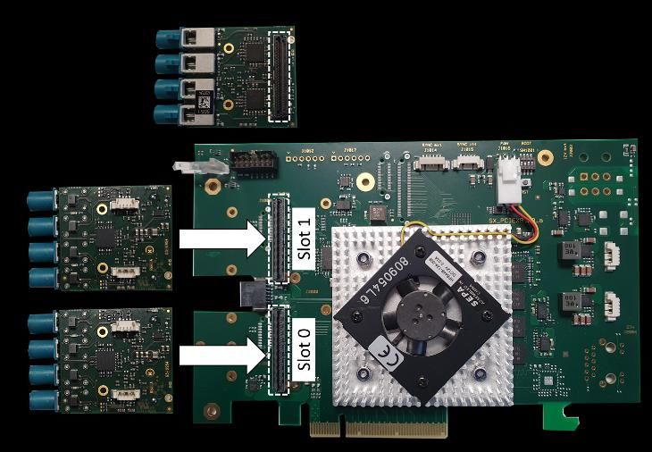
5.2 Installation of camera adapters SX camdAD3
Assembly of camera adapters SX camAD3 is done by pinning the adapter
modules into the adapter slots as shown in Figure 1.
Execute this step in an ESD protected working environment such as
ESD workstations. If not available, make sure to wear an antistatic
wrist strap electrically connected to a system chassis. Only authorized
and skilled people may do one of the procedures described below.
Figure 1: Assembly of SX camAD3 camera adapters on SX proFRAME Base
Board 3.0 (here: product variant SX proFRAME Base Board 3.0 PCIe).
5.3 Installation of SX proFRAME Base Board 3.0
5.3.1 Installation into a PCIe-based Host system
This assembly is only possible with product variant SX proFRAME Base
Board 3.0 PCIe (Art. No. 500884).
Copyright Solectrix GmbH, 2021 6SX proFRAME 3.0 - Safety Instructions, Hardware Installation (Rev. a03)
Recommended host system:
Parameter Value Comment
PCIe PCIe x8 Gen 3 or higher n.a.
n.a. n.a. n.a.
Hardware assembly and setup:
Refer to the manual of your PC and follow the instructions to assemble SX proFRAME
Base Board 3.0 PCIe into the Host system.
Execute this in an ESD protected working environment such as ESD
workstations. If not available, make sure to wear an antistatic wrist
strap electrically connected to a system chassis. Only authorized and
skilled people may do one of the procedures described below.
5.3.2 Installation into a CompactPCI-Serial system
This assembly is only possible with product variant SX proFRAME Base
Board 3.0 CompactPCI-Serial (Art. No. 500911).
Hardware requirements to the host system:
Parameter Value Comment
Processor t.b.d. n.a.
PCIe PCIe x8 Gen 3 or higher n.a.
Hardware assembly and setup:
Refer to the manual of your CompactPCI-Serial system and follow the instructions
to assemble SX proFRAME Base Board 3.0 CompactPCI-Serial into the system.
Execute this in an ESD protected working environment such as ESD
workstations. If not available, make sure to wear an antistatic wrist
strap electrically connected to a system chassis. Only authorized and
skilled people may do one of the procedures described below.
5.3.3 Installation into device box Sonnet Echo Express SE I
This assembly is only possible with product variant SX proFRAME Base
Board 3.0 PCIe (Art. No. 500884).
Hardware assembly and setup:
To connect Sonnet Echo Express SE I with your laptop use the Thunderbolt 3 cable
coming with Sonnet Echo Express SE I and connect it to your Thunderbolt con-
nector on the Laptop or PC. Refer to [SONNET_ECHO_EXP] for assembly details.
Copyright Solectrix GmbH, 2021 7SX proFRAME 3.0 - Safety Instructions, Hardware Installation (Rev. a03)
Execute this in an ESD protected working environment such as ESD
workstations. If not available, make sure to wear an antistatic wrist
strap electrically connected to a system chassis. Only authorized and
skilled people may do one of the procedures described below.
Figure 2: Thunderbolt connection at Sonnet Echo Express SE I.
Take care that you really use the Thunderbolt cable and the Thunder-
bolt connector, because USB3 and Thunderbolt 3 use the same USB-
Type-C connector but from technical side they are different.
Take care that you are using the latest software and BIOS firmware.
Do not use Thunderbolt docking stations that might cause problems.
Because Thunderbolt is sometimes not very good supported from the
BIOS and operating system. Windows usually works better than Linux
in this case.
Sonnet Echo Express SE I has two Thunderbolt connectors on the backside (see Fig-
ure 2). Both connectors may be used.
Do not forget to connect the external power supply to Sonnet Echo Ex-
press SE I. Thunderbolt allows power supply through the Thunderbolt
cable but this does not work with Sonnet Echo Express SE I.
Figure 3: Thunderbolt try icon (Windows 10).
Copyright Solectrix GmbH, 2021 8SX proFRAME 3.0 - Safety Instructions, Hardware Installation (Rev. a03)
Figure 4: Thunderbolt dialog (Windows 10, german language version).
Figure 5: Thunderbolt connect dialog (Windows 10, german language version).
Check the heartbeat LED on the slot bracket to verify SX proFRAME 3.0 Base Board
is connected correctly and is also attached to the operating system (LED shall blink
orange/green). You might have to allow your host system to connect to new Thun-
derbolt devices. Depending on the Thunderbolt software driver a Thunderbolt icon
in the tray bar may be visible (see Figure 3). A double-click on this icon opens a dia-
log as shown in Figure 4 which shows the connection status. If this connection
status is ’not connected’ you can change this by clicking the connection status. An-
other dialog window appears which allows the connection to new devices. After
completing these steps, the heartbeat LED shall blink orange/green to indicate a
working connection. If the LED lights up red please contact your IT service to check
for possible problems with your Thunderbolt settings.
Copyright Solectrix GmbH, 2021 9SX proFRAME 3.0 - Safety Instructions, Hardware Installation (Rev. a03) Solectrix Systems GmbH Dieter-Streng-Str. 4 90766 Fürth Germany Fon: +49 (0) 911 - 30 91 61 - 0 Fax: +49 (0) 911 - 30 91 61 – 299 sales@solectrix.de www.solectrix-systems.de Copyright Solectrix GmbH, 2021 10
You can also read