CHANNELS OF FILAMENTS OF AXIALLY ASYMMETRIC OPTICAL VORTICES AT A WAVELENGTH OF 1800 NM IN A LIF CRYSTAL
←
→
Page content transcription
If your browser does not render page correctly, please read the page content below
ISSN 0021-3640, JETP Letters, 2023, Vol. 117, No. 5, pp. 332–338. © The Author(s), 2023. This article is an open access publication.
Russian Text © The Author(s), 2023, published in Pis’ma v Zhurnal Eksperimental’noi i Teoreticheskoi Fiziki, 2023, Vol. 117, No. 5, pp. 337–343.

                                                                       OPTICS
                                                                  AND LASER PHYSICS

         Channels of Filaments of Axially Asymmetric Optical Vortices
                at a Wavelength of 1800 nm in a LiF Crystal
           S. A. Shlenova,b,*, V. O. Kompanetsb, V. P. Kandidova,b, S. V. Chekalinb, and E. V. Vasil’eva
                                      a
                                        Faculty of Physics, Moscow State University, Moscow, 119991 Russia
                         b
                             Institute of Spectroscopy, Russian Academy of Sciences, Troitsk, Moscow, 108840 Russia
                                                         *e-mail: shlenov@physics.msu.ru
                                  Received December 6, 2022; revised January 23, 2023; accepted January 24, 2023

          The formation of a set of filaments and plasma channels in a femtosecond optical vortex has been studied
          experimentally and numerically. A longitudinal distribution of color center tracks with a length of 1 cm writ-
          ten in a LiF crystal by an axially asymmetric beam in the single-pulse regime has been detected experimen-
          tally for the first time. It has been shown that, at a sufficient excess of the peak power over the critical value,
          two hot points on the annular profile of vortex beam separated by the phase dislocation region form sequences
          of color center tracks; each sequence in the cross section of the beam is localized near the initial hot point.
          Secondary filaments and the corresponding tracks appear with an increase in the pulse energy. The parame-
          ters of femtosecond filaments in LiF have been numerically estimated.

          DOI: 10.1134/S0021364023600155

                  1. INTRODUCTION                                                         intensity on the axis. The use of vortex beams [11, 12]
    The nonlinear propagation regime of femtosecond                                       to create plasma waveguides is promising because their
radiation with the formation of filaments is success-                                     helical phase front prevents the appearance of the field
fully used for the micromodification of transparent                                       on the optical axis. This feature is conserved under the
solid dielectrics [1, 2]. Filamentation appears when                                      self-action of radiation and the annular distribution of
the critical self-focusing power is exceeded and is usu-                                  plasma channels that form a cylindrical waveguide is
ally accompanied by the formation of plasma chan-                                         thereby supported [13].
nels, where change in the refractive index prevents the                                       Annular light bullets with a strong localization of
unlimited increase in the intensity of radiation at the                                   radiation are formed in the vortex beam at the anom-
nonlinear focus. As a result, an extended region is                                       alous group velocity dispersion. Annular bullets of the
formed, where a high radiation fluence is conserved in                                    optical vortex were previously studied theoretically in
the process of propagation of the pulse; i.e., a filament                                 the axisymmetric approximation valid for the initial
is formed [3]. The filamentation of pulses in the long-                                   stage of the formation of filaments [14]. The azi-
wavelength part of the near infrared range (λ >                                           muthal instability of radiation in the medium with
1500 nm) is of particular interest. In fused silica and                                   cubic nonlinearity leads to the breaking of the axial
fluorides, such radiation falls in the region of anoma-                                   symmetry and to the formation of a set of coupled fil-
lous group velocity dispersion, where the self-focusing                                   aments with the conservation of the annular structure
of the beam is accompanied by the time self-compres-                                      of the beam [15, 16]. Furthermore, the axial symmetry
sion of radiation, which results in the formation of so-                                  under real experiment conditions can be broken
called “light bullets,” i.e., quasistable wave packets                                    already at the stage of formation of an optical vortex
with a high spatiotemporal localization of intense                                        because of the spatial nonuniformity of the output
radiation [4–6].                                                                          beam and the used phase transparency [17]. The fila-
    An important factor in applied problems of the for-                                   mentation of an axially asymmetric optical vortex with
mation of plasma channels with a given configuration                                      the topological charge m = 1 at a wavelength of
and modification of transparent dielectrics is the pos-                                   1800 nm was studied in [18] by the laser coloration
sibility of femtosecond filamentation control. The                                        method in the LiF crystal [19]. A high sensitivity of
idea of the creation of a virtual waveguide by a set of                                   this method made it possible to write tracks of long-
plasma channels located on a circle [7] was theoreti-                                     lived color centers in the single-pulse regime and to
cally studied in [8, 9]. To form a cylindrical set of fila-                               measure the length of the continuous part of a track.
ments, the authors of [10] used a controlled deform-                                      Color centers and the plasma in the filament are gen-
able mirror, which formed a annular beam with zero                                        erated through multiphoton processes with close mul-

                                                                                     332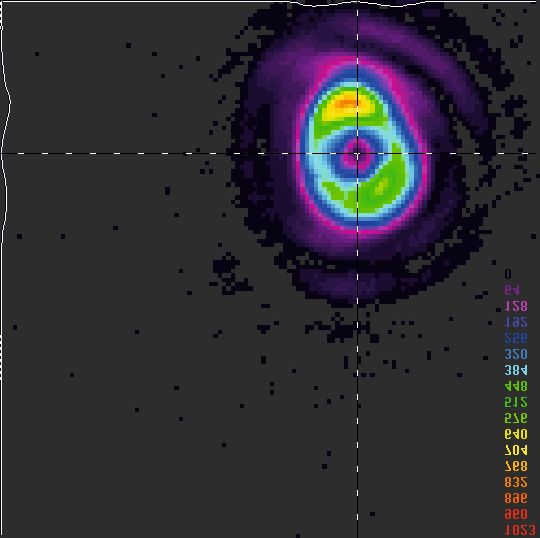
CHANNELS OF FILAMENTS OF AXIALLY ASYMMETRIC OPTICAL VORTICES                                                 333

                                                                                                     1 cm

                                                                     Fig. 2. (Color online) Schematic of the recording and
                                                                     detection of the luminescence of color centers induced by
                                                                     the optical vortex in the LiF crystal.

                                                                  The phase shift of the light field at these hot points is
                                                                  close to 180°.
                                                                      To write color center tracks, focused vortex beams
                                                                  were fed to the input of the sample. The focal plane of
   Fig. 1. (Color online) 1 × 1-mm profilometer image of the      the converging lens was displaced inside the crystal at
   optical vortex at a wavelength of 1800 nm at a distance of     a distance of 0.7 cm; as a result, the beam was geomet-
   0.7 cm from the focal plane of the converging lens with a      rically focused on the output face of the crystal taking
   focal length of 34.5 cm. The phase dislocation is located at   into account that the refractive index of the LiF crystal
   the intersection of dashed lines.                              at a wavelength of λ = 1800 nm is n0 = 1.38 . Tracks of
                                                                  long-lived color centers written in the LiF crystal by
                                                                  filaments of the optical vortex were recorded by a
tiphoton orders. This allows one to study the arrange-
                                                                  Nikon D800 digital camera through the lateral and
ment and parameters of plasma channels at the fila-               output faces of the sample illuminated by continuous
mentation of femtosecond pulses using color center                radiation at a wavelength of 455 nm. The length of the
tracks [20, 21].                                                  crystal along the propagation axis of the vortex beam
    In this work, the formation of a set of coupled fila-         was l = 1 cm (Fig. 2), which allows the longitudinal
ments and plasma channels in a femtosecond optical                detection of filament tracks through a microscope
vortex has been studied experimentally and numeri-                with a ×10 objective and a numerical aperture of
cally. Filament tracks in the LiF crystal are detected at         NA = 0.3.
different energies of a femtosecond pulse by the laser                The appearance of the first filaments was observed
coloration method. The peak intensity, fluence, and               at an initial pulse energy of 7.5 μJ, which can be
the maximum plasma density in the channels of the                 accepted as the threshold for the formation of a fila-
filament are estimated.                                           ment in the vortex femtosecond pulse beam obtained
                                                                  at the experimental setup. Note that the threshold
                                                                  energy at which the critical self-focusing power is
                    2. EXPERIMENT                                 reached in the pulse under consideration inde-
                                                                  pendently estimated from the beginning of generation
   The set of coupled filaments was experimentally                of visible supercontinuum radiation in a longer LiF
studied at a laboratory setup based on the ISAN fem-              crystal is also 7.5 μJ.
tosecond laser complex [18]. The axially asymmetric                   The energies near the maxima of two bright spots in
optical vortex with a topological charge m = 1 was                Fig. 1 differ by more than a factor of 2; consequently,
formed from a Gaussian beam using a spiral phase                  filamentation occurred at two hot point at different
plate [17] and the subsequent focusing by the converg-            distances. The presence of the phase dislocation pre-
ing lens with a focal length of 34.5 cm. The duration of          vents the effective energy exchange between the hot
pulses at a level of e −1 at the input of the LiF crystal         points in the process of propagation of the pulse in the
sample was 67 fs. Figure 1 shows the typical distribu-            nonlinear medium [18]. As a result, the initial stage of
tion of the fluence in the optical vortex at the input of         filamentation occurs independently at each of the hot
the crystal. Two hot points with different fluences are           points located on the diameter of the annular beam
clearly seen (two bright spots) in the cross section of           when the critical power for self-focusing is exceeded.
the beam; they are separated by the region of the min-            This is confirmed by the analysis of the dependence of
imum fluence with the phase dislocation at its center.            the distance to the start of filamentation zfil on the

   JETP LETTERS         Vol. 117    No. 5    2023
334 SHLENOV et al.
Fig. 3. (Circles) Distance to the onset of the filamentation
zfil of the axially asymmetric optical vortex in the LiF crys-
tal versus the pulse energy in comparison with (solid line)
the distance to the nonlinear focus calculated by the Mar-
burger formula for the Gaussian beam with a radius
r0 = 58 μm focused to 1 cm.
pulse energy using the Marburger formula [22], which
is valid for Gaussian beams. According to the experi-
ment, the peak power at the brightest hot point (in the
lower part of the beam in Fig. 1) in the 7.5-μJ pulse
corresponds to the critical power for self-focusing.
The characteristic transverse scale r0 = 58 μm of this
hot point is accepted as the radius of the Gaussian
beam.
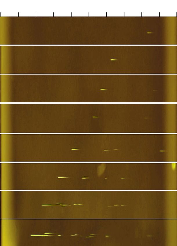
Fig. 4. (Color online) Transversely magnified micrographs
The distance to the beginning of filamentation was of the luminescence of color centers written in the LiF
determined with averaging over two single pulses. crystal 1 cm long by filaments of the optical vortex at the
Good agreement of the experimental dependence of indicated energies of the pulse propagating from left to
right.
the self-focusing distance on the pulse energy with
numerical estimates by the Marburger formula taking
into account the geometrical focusing of the beam [23] 17.2 μJ at a distance of about 6.5 mm from the input
at a distance of l = 1 cm in a wide range of pulse ener- face of the crystal.
gies (Fig. 3) indirectly indicates that filamentation in
the axially asymmetric optical vortex is indeed devel- With a further increase in the energy, the filament
oped independently at hot points separated by the dis- from this hot point, as well as that from the first hot
location region. point, begins at a shorter distance. The coordinates of
all detected tracks from the 23-μJ pulse are shown in
With an increase in the pulse energy, the beginning Fig. 5 in two mutually orthogonal lateral projections
of filamentation is shifted toward the input plane of and in the frontal projection. The primary tracks from
the crystal, as clearly seen in Fig. 4, where tracks writ- different hot points are given in red and blue. Tracks of
ten by single pulses with different energies are pre- secondary filaments formed after the defocusing of
sented in horizontal windows marked by white lines. radiation from primary filaments are shown in black.
Pulses with low energies below 10.5 μJ provide a con- The primary track from the second hot point and the
tinuous track with a visible length of about 400 μm. A second track near the first hot point are clearly distin-
weak short track is observed in the propagation direc- guished in Fig. 6b, because they are simultaneously
tion of 11.7- and 12.5-μJ pulses at a distance slightly observed in one cross section of the crystal. The trans-
longer than 2.5 mm from the first track. With a further verse size of the track of the second, just formed, fila-
increase in the pulse energy, the number of tracks in ment is much smaller than the transverse size of the
the propagation direction of pulses increases and the track from the first hot point, where a higher energy is
distance between them decreases. stored and the plasma defocusing of radiation is
The second hot point with a lower energy is the already manifested when color centers are written.
center of nucleation of the second filament, which is Two filaments formed by two hot points on the
formed at a larger distance than the first one. It was beam profile do not interact with each other because
observed in experiments first at a pulse energy of they are separated by the region with the phase dislo-
JETP LETTERS Vol. 117 No. 5 2023CHANNELS OF FILAMENTS OF AXIALLY ASYMMETRIC OPTICAL VORTICES 335
Fig. 5. (Color online) (Left panels) Lateral ( x, z) and ( y, z) and (right panel) frontal ( x, y) projections of the tracks of color centers
written by the 23-μJ pulse. The initial tracks from the first and second hot points are shown in red and blue, respectively. The
longitudinal coordinate z is measured from the input plane of the crystal.
cation [18]. Nevertheless, the secondary filament is At high pulse energies, already the first tracks from
observed in the cross section (Fig. 6c) at the position two hot points can be observed simultaneously in one
determined by the interference of radiation diverging cross section (see the top two panels of Fig. 4). The
from the plasma channel of the primary filament and track from the second hot point in the 38-μJ pulse
a fraction of radiation of the pulse that has not yet been begins just before the end of the primary track from the
self-focused. The transverse shift of coordinates first hot point (Fig. 6d). Secondary filaments appear
(Fig. 5) and images (Fig. 6) of tracks at different dis- on the sides of primary filaments already at the end of
tances z is due to the distribution of the phase of the the first tracks from both hot points (Fig. 6e). These
secondary filaments can move toward each other,
light field in the vortex beam, as well as to the focusing rounding the phase dislocation region. This finally
of the beam and to a small inclination of the optical results in their interaction on the annular beam profile
axis. We failed to detect the rotation of color center with the possible partial summation of their energies at
tracks, which should occur upon the filamentation of the appearance of the next secondary filament
the vortex beam and which is indicated by experimen- (Fig. 6f).
tal data for longer atmospheric tracks [24] and by the
The characteristic length of the first track in the
numerical simulation [18]. The estimated beam rota-
53-μJ pulse can exceed 1 mm. A sequence of 5000 pul-
tion in the transverse plane in the continuous part of ses induces a cumulative effect and the writing of a
the track in our experiment is no more than 1°−2° . A continuous series of color center tracks beginning near
larger rotation could be observed in the entire track, the input face of the crystal to the output face at a dis-
but it is formed as a result of the successive appearance tance of 1 cm.
of secondary filaments, which are quite random, being
shifted in the cross section of the beam independently
of the spiral phase. A special experiment with the for- 3. NUMERICAL SIMULATION
mation of two hot points with the same power on the The presence of the phase dislocation in the optical
beam diameter can improve the observation of the vortex and, as a result, the independent formation of
rotation of filaments by detecting the rotation of the filaments at two hot points in its cross section allow
axis connecting the centers of color center tracks from one to estimate the characteristic parameters of fila-
these two points in the cross section of the track. ments using the model of a single Gaussian beam. To
JETP LETTERS Vol. 117 No. 5 2023336 SHLENOV et al.
Fig. 6. 0.42 × 0.42-mm cross sections of the tracks of color centers written by a single pulse with an energy of (a–c) 23 and (d–f)
38 μJ at distances of z = (a) 3.5, (b) 4.90, (c) 6.60, (d) 3.25, (e) 3.50, and (f) 3.95 mm from the input face of the LiF crystal.
estimate the plasma density, peak intensity, and flu- Δnpl(Ne), we used the kinetic equation for the free
ence in filaments of axially asymmetric optical vortex electron density in the plasma N e (r, t, z) consistent
in the LiF crystal, we performed a series of numerical with the field A :
experiments within the known previously tested math-
ematical model of the nonlinear propagation of the
femtosecond pulse in the quasioptical approximation
∂N e
∂t
2
( ) 2
( )
= RE A ( N 0 − N e ) + νi A N e − β N e, (2)
including the operator of wave nonstationarity Tˆ [14,
15, 25]:
( ) 2
where field ionization whose RE A rate was deter-
2ik0 ∂A = Tˆ −1Δ ⊥ A + Tˆ −1 1 mined within the Keldysh model, avalanche ioniza-
∂z 2π tion, and recombination were taken into account.
+∞
× (k (ω + Ω) − (k0 + k1Ω) )A exp{i Ωt}d Ω
2 2
0
−∞ (1)
2k 2
( )
2k 2 −1
+ 0 Tˆ Δnk A A + 0 Tˆ Δnpl ( N e ) A
n0
2
n0
( ( ) )
+ iTˆ −2σA − ik0 α A + δ A,
2
where A(r, t, z) is the complex amplitude of the light
field and A (r, Ω, z) is its frequency spectrum. The
terms on the right-hand side of the equation of propa-
gation (1) describe the diffraction of the beam, the dis-
persion of the pulse (in the spectral space using the
Sellmeier formula for the refractive index), Kerr non-
linearity (instantaneous and inertial components), Fig. 7. Numerically estimated (filled circles) maximum
plasma nonlinearity, inverse bremsstrahlung, nonlin- electron density N e and (empty circles) maximum fluence
ear absorption, and extinction. To calculate the F versus the ratio of the peak power to the critical one at the
plasma addition to the refractive index of the medium hot point of the axially asymmetric optical vortex.
JETP LETTERS Vol. 117 No. 5 2023CHANNELS OF FILAMENTS OF AXIALLY ASYMMETRIC OPTICAL VORTICES 337
We considered the propagation of the Gaussian author(s) and the source, provide a link to the Creative Com-
beam with the radius r0 = 58 μm with the Gaussian mons license, and indicate if changes were made. The images
envelope of the 67-fs pulse at a wavelength of 1800 nm or other third party material in this article are included in the
with different peak powers that was focused at 1 cm in article’s Creative Commons license, unless indicated other-
the LiF crystal. Figure 7 presents the peak electron wise in a credit line to the material. If material is not included
density N e and the peak fluence F. An increase in the in the article’s Creative Commons license and your intended
peak pulse power from 1.07 to 7.0 of the critical self- use is not permitted by statutory regulation or exceeds the
focusing power (corresponding to an increase in the permitted use, you will need to obtain permission directly
pulse energy in the experiment from 8 to 53 μJ) results from the copyright holder. To view a copy of this license, visit
http://creativecommons.org/licenses/by/4.0/.
in an almost triple increase in the density N e and an
increase in the fluence by a factor of 1.7. The maxi-
mum plasma density in the filament channel reaches REFERENCES
0.04% of the neutral density N 0, and the maximum
fluence is 2.75 J/cm2. The maximum peak intensity of 1. K. Yamada, W. Watanabe, T. Toma, K. Itoh, and J. Ni-
shi, Opt. Lett. 26, 19 (2001).
the pulse is about 1014 W/cm2 and weakly depends on
its initial energy. 2. W. Watanabe, T. Asano, K. Yamada, K. Itoh, and
J. Nishii, Opt. Lett. 28, 2491 (2003).
3. V. P. Kandidov, S. A. Shlenov, and O. G. Kosareva,
4. CONCLUSIONS Quantum Electron. 39, 205 (2009).
To summarize, the longitudinal distribution of 4. L. Berge and S. Skupin, Phys. Rev. Lett. 100, 113902
color center tracks with a length of 1 cm written in a (2008).
LiF crystal by an axially asymmetric optical vortex at a
5. V. P. Kandidov, E. D. Zaloznaya, A. E. Dormidonov,
wavelength of 1800 nm in the single-pulse regime has V. O. Kompanets, and S. V. Chekalin, Quantum Elec-
been detected experimentally for the first time. It has tron. 52, 233 (2022).
been shown that, at a sufficient excess of the peak
power over the critical value, two π-phase-shifted 6. E. D. Zaloznaya, A. E. Dormidonov, V. O. Kompanets,
maxima of the light field intensity form color center S. V. Chekalin, and V. P. Kandidov, JETP Lett. 113,
787 (2021).
tracks each localized near the initial hot point in the
cross section of the beams. With an increase in the 7. A. Dormidonov, V. Valuev, V. Dmitriev, S. Shlenov,
pulse energy, secondary filaments appear and induce and V. Kandidov, Proc. SPIE 6733, 67332S (2007).
color center tracks. When the ratio of the peak power 8. V. V. Valuev, A. E. Dormidonov, V. P. Kandidov,
to the critical value reaches 7–8, the length of the con- S. A. Shlenov, V. N. Kornienko, and V. A. Cherepenin,
tinuous part of the track can exceed 1 mm. The J. Commun. Technol. Electron. 55, 208 (2010).
parameters of filaments have been numerically esti- 9. M. Alshershby, H. Zuoqiang, and L. Jingquan, J. Phys.
mated, and it has been shown that the peak fluence D: Appl. Phys. 45, 265401 (2012).
and, the more so, the plasma density in the filament
increase with the pulse energy at an almost constant 10. M. Chateauneuf, S. Payeur, J. Dubois, and J.-C. Kief-
fer, Appl. Phys. Lett. 92, 091104 (2008).
maximum intensity of about 1014 W/cm2. The depen-
dences of these parameters on the peak pulse power 11. L. Allen, M. W. Beijersbergen, R. J. C. Spreeuw, and
tend to saturation. When the ratio of the peak power to J. P. Woerdman, Phys. Rev. A 45, 8185 (1992).
the critical value reaches 7, the plasma density reaches 12. V. V. Kotlyar and A. A. Kovalev, Accelerating and Vortex
0.04% of the density of neutral molecules. Laser Beams (Fizmatlit, Moscow, 2018; Routledge,
London, 2019).
FUNDING 13. S. Fu, B. Mahieu, A. Mysyrowicz, and A. Houard, Opt.
Lett. 47, 5228 (2022).
This work was supported by the Russian Science Foun-
14. E. V. Vasil’ev, S. A. Shlenov, and V. P. Kandidov, Laser
dation, project no. 18-12-00422. Phys. Lett. 15, 115402 (2018).
15. J. M. Soto-Crespo, D. R. Heatley, and E. M. Wright,
CONFLICT OF INTEREST Phys. Rev. A 44, 636 (1991).
The authors declare that they have no conflicts of interest. 16. A. Vincotte and L. Berge, Phys. Rev. Lett. 95, 193901
(2005).
17. S. A. Shlenov, E. V. Vasilyev, S. V. Chekalin, V. O. Kom-
OPEN ACCESS panets, and R. V. Skidanov, J. Exp. Theor. Phys. 132,
This article is licensed under a Creative Commons Attri- 334 (2021).
bution 4.0 International License, which permits use, sharing, 18. S. A. Shlenov, V. O. Kompanets, A. A. Dergachev,
adaptation, distribution and reproduction in any medium or V. P. Kandidov, S. V. Chekalin, and F. I. Soifer, Quan-
format, as long as you give appropriate credit to the original tum Electron. 52, 322 (2022).
JETP LETTERS Vol. 117 No. 5 2023338 SHLENOV et al.
19. E. F. Martynovich, A. V. Kuznetsov, A. V. Kirpich- 23. A. A. Dergachev, A. A. Ionin, V. P. Kandidov, D. V. Mo-
nikov, E. V. Pestryakov, and S. N. Bagaev, Quantum krousova, L. V. Seleznev, D. V. Sinitsyn, E. S. Sun-
Electron. 43, 463 (2013). chugasheva, and S. A. Shlenov, Laser Phys. 25, 065402
20. A. V. Kuznetsov, A. E. Dormidonov, V. O. Kompanets, (2015).
S. V. Chekalin, and V. P. Kandidov, Quantum Elec- 24. P. Polynkin, C. Ament, and J. V. Moloney, Phys. Rev.
tron. 51, 670 (2021). Lett. 111, 023901 (2013).
21. A. E. Dormidonov, E. D. Zaloznaya, V. O. Kompanets,
S. V. Chekalin, and V. P. Kandidov, JETP Lett. 116, 25. T. Brabec and F. Krausz, Phys. Rev. Lett. 78, 3282
436 (2022). (1997).
22. J. H. Marburger, Prog. Quantum Electron. 4, 35
(1975). Translated by R. Tyapaev
JETP LETTERS Vol. 117 No. 5 2023You can also read


