Automated People Mover "Crystal Mover" for Singapore Changi International Airport
←
→
Page content transcription
If your browser does not render page correctly, please read the page content below
Au t o m a t e d Pe o p l e M ov e r
                                                                            "Crystal Mover" for Singapore
                                                                            Changi International Airport

                                                                                                                 MAKOTO KASHIWA* 1
                                                                                                             HIROYUKI MOCHIDOME* 1
                                                                                                                 ARATA YAMAMOTO* 1

   Mitsubishi Heavy Industries, Ltd. (MHI) received an order for its Crystal Mover for Changi International Air-
port of the Civil Aviation Authority of Singapore (CAAS), to serve as the transportation system connecting its
terminals where the newly constructed Terminal 3 is a symbol of the New Singapore Changi Airport. The new
transportation system is characterized by its innovative and futuristic vehicle design, by a unique design for
connecting to a new guideway through the retrofitting of the structure of the existing system, and by realization of
the request for a seamless transition service from the existing system to the new system, thus providing a com-
plete system which connects all the terminals, Terminals 1 to 3. This paper reports on the new Crystal Mover and
its construction process.

1. Introduction                                                             2. Automated People Mover (APM) System Configu-
                                                                               ration
    During recent years in South East Asia and East Asia,
new airports have been established and existing airports                       The Singapore Changi International Airport APM
have been expanded. These include, for example,                             System consists of 6,400 m of single-lane track. This
Bangkok New Airport and Chubu (Nagoya) Airport. The                         includes about 1,300 m of the retrofitted existing sys-
economic development of these regions has enhanced                          tem. The system configuration is composed of two
their network with Asian countries and also with Eu-                        independent guideway segments, PMS/North (4,100 m
rope, Oceania and North America. These airports                             in total length) and PMS/South (2,300 m in total length),
continue to grow through the expansion of their existing                    each having an independent maintenance area. The
functions or the addition of new functions, and are more                    PMS/South provides services between Terminal 2 and
comfortable and convenient air transit hubs. They are                       Terminal 3, Terminal 3 main building and South Pier
also regional bases for efficiently connecting active traf-                 for transit passengers moving between the terminals and
fic in Asian countries.                                                     passengers after immigration clearance. The PMS/North
    In 2002, the Civil Aviation Authority of Singapore                      provides services between Terminal 1, Terminal 2, and
(CAAS) planned to expand its airport function by con-                       Terminal 3 for public passengers. This system also links
structing Terminal 3, and they selected MHI's Crystal                       up the different airport public transport facilities, taxi
Mover as the transportation system between terminals.                       stands, subways and car parks, allowing more convenient
CAAS requested at the time of adoption that the new                         access to the city.
system should feature innovative vehicle design, retro-                        This system consists of seven stations (A-South, A, B,
fitting the structures of the existing system which has                     C, D, E, and F), each giving the name of the nearest
been in revenue service since 1990, and a seamless tran-                                                                       Figs
                                                                                                                               Figs.. 1
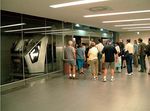
                                                                            boarding gate for easy recognition for passengers (Figs
sition to the new system, which MHI has endeavored to                            2
                                                                            and ).
do. Concerning the transition from the existing system                         The APM Main Operation Control Center is located
to the new one, the construction started with the retro-                    inside the maintenance office near A-South Station and
fitting of a part of the existing system for the Interim                    the Standby Satellite Control Center is located in the
Operation which was then followed by further expan-                         center of the Terminal 3 building. Either of the control
sion to Terminal 3 for the Overall Operation. This                                                                            Fig. 3
                                                                            centers can be used to control the entire system (Fig. 3).
undertaking was the first experience of its type for MHI.                      In the contract of this project, MHI supplies the con-
The "interim revenue service" section was started on                        crete running plinths, guideways, station equipment,
March 16, 2006, and entered commercial operation. The                       power distribution system, signaling system, communi-
entire system is now in the process of test runs prepara-                   cation system, maintenance facilities, and designing,
tory for the expansion and handover of the complete                         manufacturing, installing and testing and commission-
system in June 2007.                                                        ing of the vehicles.

*1 Plant and Transportation Systems Engineering & Construction Center                       Mitsubishi Heavy Industries, Ltd.
                                                                                            Technical Review Vol. 44 No. 2 (Jul. 2007)
                                                                        1
A-South
Terminal 3
A (Under B C
construction)
Terminal 1
Control Tower
F E D
Terminal 2
PMS/South PMS/North
Fig. 1 Overall layout of airport
Fig. 2 APM platform
Fig. 4 Original Crystal Mover and rendering image for
Changi Airport
Fig. 3 Main operation control center
Mitsubishi Heavy Industries, Ltd.
Technical Review Vol. 44 No. 2 (Jul. 2007)
2tem complies with the Signaling and Safety Standard, while
3. Crystal Mover vehicles the automatic operation system complies with the stan-
MHI has delivered 16 Crystal Mover vehicles to dards of the Urban Transportation System, utilizing a train
Singapore Changi Airport, ten of which are allocated to detection system based on the check-in/check-out principle
PMS/North and six to PMS/South. Five different designs and the well proven automatic train control system.
with innovative external face images derived from the In this APM system, as the overrun protection dis-
original Crystal Mover design were proposed to the cli- tance from the stopping position for the vehicle to the
ent, who finally selected the vehicle model shown in track end is short due to architectural restrictions, the
Fig
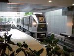
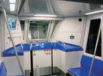
Fig.. 4 . MHI has developed the vehicle shown in Figs. 5, system adopted an ORP (overrun protection system) by
6 , and 7 through a design process focused on faithfully Fig. 8
on-board ATP (automatic train protection) (Fig. 8). When
realizing the innovative and leading-edge rendering of a train enters the ORP signal aspect section, the on-board
the original design. This vehicle was awarded the Good ATP device creates the ORP control pattern in a manner
Design Award 2006, instituted by the Ministry of which protects the fixed-point stop control pattern by
Economy, Trade and Industry of Japan since 1957. the on-board ATO (automatic train operation) device. If
MHI can flexibility respond to a variety of operations, the train speed overshoots the ORP control pattern, the
from a one car operation to multiple coupled-car opera- emergency brake is activated, safely bringing the train
tions, depending upon the system requirements. to an emergency stop.
Actually, a two coupled-car operation is in operation be- 4.2 Operation control system
tween Terminals 1 and 2, with the intention of expanding As the line currently in commercial operation is used
it to a three coupled-car operation in the future. to supply and withdraw vehicles, this must be taken into
account when marshaling vehicles and operation becomes
4. Signaling/communication systems more complicated. To realize efficient operability, a pro-
4.1 Signaling system grammed route control based on selection of the start
In the Changi Airport APM system, the signaling sys- and end points has reduced the operators' burden.
Another characteristic feature regarding the opera-
tion of this system is the by-pass operation used between
Terminals 2 and 3 as shown in Figs. 9 and 10 10, where
trains are placed under synchronous control so that they
ATO Operation
ORP Pattem
ATP25 ORP25
Fig. 6 Vehicle for Changi Airport
Transponder Track End
ATP Loop Limit
ORP
Section
Fig. 8 Overrun protection system
Fig. 7 Vehicle interior
Station X
Train B
Bypass
Train A
Station Y
Fig. 9 Bypass shuttle Fig. 10 Bypass shuttle (photo)
Mitsubishi Heavy Industries, Ltd.
Technical Review Vol. 44 No. 2 (Jul. 2007)
3depart and arrive at each corresponding station at the has been adopted for voice communication and data
same time. Specifically, the station departing times are transmission between vehicles and control which are
synchronized by the count of the station dwell time which especially important for train operation. The PMS North
is automatically adjusted based on the stoppage state at area and the PMS South area each have two antennas
the station. Also, the train speed is adjusted by ATO to cover the entire area. By using the 2.4 GHz band for
which recognizes signals which are sent from the way- the on-board CCTV system for on-board supervision
side control devices to the on-board control device at the Fig
Fig.. 11 ) and the 5.2 GHz band for the on-board informa-
(Fig
time of departure from a station so that the crossing tion display system, flight information, advertisements
times in the bypass section are optimized and their ar- Fig. 12
etc. (Fig. 12), the radio communication system sends and
rival times are synchronized. receives image data and information data between ve-
4.3 Communication system hicles and control. For transmission of critical control
A radio space wave system using three channels (voice, data, an optical fibre transmission device equipped with
voice control and data transmission) on the 400 MHz fre- the redundancy configuration of an optical transmission
quency band in accordance with application and approval line is located at each station, helping ensure reliability.
Fig. 11 On-board CCTV camera Fig. 12 Flight information
2002 2003 2004 2005 2006 2007
Design
Design Work May. 2002 Design
Guideway Construction
Guideway Construction May. 2003
BY Other Contractor Construction
Construction
22KV Energized Jun. 2005
DC750V Energized Sep. 2005
Vehicle Delivery Oct. 2005
Completion Vehicle Jun. 2006
Delivery
Installation for Interim Dec. 2004 Interim
Installation for Overall Dec. 2004 Overall
Installation for Phase2 Apr. 2006 Phase 2
Test & Commissioning
Test for Interim Operation Oct. 2005 Interim
Test for Overall Operation May. 2006 T&C Overall-Phase 2
Operation
Interim Operation Mar. 2006 Interim Operation
Overall Operation Jul. 2007 Overall
Operation
Fig. 13 Project schedule
Mitsubishi Heavy Industries, Ltd.
Technical Review Vol. 44 No. 2 (Jul. 2007)
4and running plinths were removed by the client's con-
5. Construction tractor, and retrofitting including adding a parapet wall
The construction schedule has two different phases along our guideways and alignment (side guide system)
(Figs. 13 and 14
Figs. 14). The first phase consisted of the con- and construction of the station were carried out. On
struction work of the Interim Operation in which the other side of the tracks, commercial operation con-
retrofitting of the existing guideway was performed for com- tinued up to the commencement of operation of the new
mercial operation starting at an early date and the Overall system. The retrofitting work for which the client was
Operation (accounting for 70% of the total work) in which responsible started in October 2004, immediately fol-
Terminal 3 is connected to Terminals 1 and 2 after the new lowed by start of the installation work of the new system
guideways are built. They are referred to as Interim and Fig. 15
in December 2004 (Fig. 15).
Overall respectively. (2) Step 2
The second phase consists of the construction work (ac- In about nine months from December 2004 to Sep-
counting for 30% of the total work) utilizing the existing tember 2005, system construction including the
system structure, which we perform by stopping the exist- running plinths, guideways, and cabling work was com-
ing system after commercial operation in the Interim pleted for a section of about 550 m in length. In October
Operation is started. We call this construction "Phase 2". 2005, two Crystal Mover vehicles were lifted up and
Two challenging missions were requested in Phase 2, test runs were started. After test runs which lasted to
moving to the new system by utilizing the existing system the middle of March 2006, the interim revenue service
structure and speedily changing over from the existing operation was started officially on March 16, 2006
system to the new system without any long shutdown of Fig
Fig.. 16
(Fig 16). Simultaneously with the start of this interim
commercial operations. The project has progressed in ac- revenue service operation, the existing system stopped
cordance with the construction sequence and is now in Step and the new retrofitting work was started.
3 below. In parallel with this work, the construction of sys-
(1) Step 1 tems for the new guideway, the Overall (accounting for
After operation on one side (inside the red frame) of 70% of the total work), was carried out in the begin-
the existing double tracks was stopped, the guideways ning of 2005, including construction of the running
plinths, guideways, power distribution system, signal-
ing system, communication system, station facilities,
: Overall (Phase 1)
: Interim (in commercial operation) and maintenance facilities. After completion in July
: Phase 2 2006, these systems are now undergoing testing and
C
commissioning.
TERMINAL 3 TERMINAL 1 (3) Step 3
B
D Following commencement of the Interim Operation,
construction work for the rest of the existing guideway
A
A-South section and the new guideway section connected to the
F E existing guideway section were started. As of March
TERMINAL 2 2007, almost all the construction has been completed
and test runs are under way. The double tracks were
expanded to four tracks which were arranged in paral-
lel. Test runs are now under way toward the expected
Fig. 14 Entire guideway Figs. 17 and 18
handover in July 2007 (Figs. 18).
Start of retrofitting Commercial After retrofitting, commercial
Revenue service ceased.
for new line operation continued operation started on March 16, 2006.
Fig. 15 Retrofitting existing system (Step 1) Fig. 16 Retrofitting existing system (Step 2)
Mitsubishi Heavy Industries, Ltd.
Technical Review Vol. 44 No. 2 (Jul. 2007)
5Revenue service Revenue
service
Construction
of new track
Retrofitting of existing track Construction of new track
Retrofitting of
Fig. 17 Retrofitting existing system (Step 3) existing track
Fig. 18 Retrofitting existing system (Step 3 photo)
Fig. 19 Interim revenue service
6. Interim Operation
Fig. 20 Airport passengers
The Interim Commercial Operation in the advanced
revenue operation section (between Terminals 1 and 2) was
8. Conclusion
started on March 16, 2006 and 14 months have passed since
then. Through its flexible response to the client's requirements
Currently, the system is operated in a two-vehicle con- and careful planning and implementation, MHI has suc-
figuration using one vehicle for transit passengers and the cessfully overcome restrictive conditions caused by use of
Fig. 19
other for public passengers (Fig. 19). the existing systems, and has accomplished the changeover
Each day 19.5 hours of service is available from 6:00 of the systems without adversely affecting the existing sys-
am to 1:30 am at intervals of about 5 minutes. In these 14 tem or creating a long downtime. Also with regard to the
months, approximately 114,000 km has been traveled over commercial operation, it has gained trust because of its
about 8,000 hours and the average availability has been high availability.
99.8%. This commercial operation has achieved high avail- Now our project has reached the final stage prior to
ability despite there being no spare vehicle available for handover of the overall system and we are endeavoring to
replacement during the interim revenue service and time safely complete the work for commencement of the overall
for maintenance is limited to nighttime hours. This In- revenue service.
terim Operation will be continued up to the commencement It is our strong determination to continuously provide s
of the overall revenue service, where it is intended that safe and pleasant APM system so that passengers can move
the interim system will be speedily replaced by the overall enjoyably and comfortably inside the airport (Fig. Fig. 20
20).
system without affecting the revenue service. Lastly, but by no means least, we would like to express
our sincere gratitude to all the parties concerned for their
7. Commencement of overall revenue service guidance and the cooperation extended to us in the course
Currently, the Interim Operation is continuing and, on of implementation of this APM System Project.
completion of the newly constructed Terminal 3, full-scale
commercial operation will commence. When the overall
revenue service starts, each station will be connected by a
shuttle service operated for 24 hours in three different
patterns, Peak mode, Off-peak mode, and On-call mode,
according to the number of passengers using the airport. Makoto Kashiwa Hiroyuki Mochidome Arata Yamamoto
Mitsubishi Heavy Industries, Ltd.
Technical Review Vol. 44 No. 2 (Jul. 2007)
6You can also read


