ATN OTS-XLT HANDHELD THERMAL MONOCULAR - AMERICAN TECHNOLOGIES
←
→
Page content transcription
If your browser does not render page correctly, please read the page content below
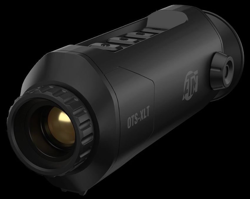
ATN OTS-XLT
HANDHELD THERMAL MONOCULAR

        MANUAL

          AMERICAN
        TECHNOLOGIES
          NETWORK
            CORP.
R E G U L AT O RY I N F O R M AT I O N                                                                         TA B L E O F C O N T E N T S
     FCC Information                                                                                                   1. SAFETY INSTRUCTION . . . . . . . . . . . . . . . . . . . . . . . . . . 4
   FCC compliance: This equipment has been tested and found to comply                                                  2. SPECIFICATIONS. . . . . . . . . . . . . . . . . . . . . . . . . . . . . . . 5
with the limits for a Class A digital device, pursuant to part 15 of the FCC Rules.                                    3. OVERVIEW. . . . . . . . . . . . . . . . . . . . . . . . . . . . . . . . . . . . . 5
These limits are designed to provide reasonable protection against harmful                                                 3.1. Brief Description. . . . . . . . . . . . . . . . . . . . . . . . . . . . . . . 5
interference when the equipment is operated in a commercial environment.
This equipment generates, uses, and can radiate radio frequency energy and,                                                3.2. Function. . . . . . . . . . . . . . . . . . . . . . . . . . . . . . . . . . . . . 5
if not installed and used in accordance with the instruction manual, may cause                                             3.3. Appearance. . . . . . . . . . . . . . . . . . . . . . . . . . . . . . . . . . 6
harmful interference to radio communications. Operation of this equipment in                                                    3.3.1. Button. . . . . . . . . . . . . . . . . . . . . . . . . . . . . . . . . . 6
a residential area is likely to cause harmful interference in which case the user                                               3.3.2. Interface. . . . . . . . . . . . . . . . . . . . . . . . . . . . . . . . 7
will be required to correct the interference at his own expense.
                                                                                                                       4. PREPARATION . . . . . . . . . . . . . . . . . . . . . . . . . . . . . . . . . 7
   FCC Conditions                                                                                                          4.1. Charge Device. . . . . . . . . . . . . . . . . . . . . . . . . . . . . . . . 7
   This device complies with part 15 of the FCC Rules. Operation is subject to                                             4.2. Power On/Off. . . . . . . . . . . . . . . . . . . . . . . . . . . . . . . . . 8
the following two conditions:
                                                                                                                           4.3. Menu Description. . . . . . . . . . . . . . . . . . . . . . . . . . . . . . 8
   1. This device may not cause harmful interference.
   2. This device must accept any interference received, including interference                                        5. IMAGE SETTINGS. . . . . . . . . . . . . . . . . . . . . . . . . . . . . . . 9
      that may cause undesired operation.                                                                                  5.1. Adjust Diopter. . . . . . . . . . . . . . . . . . . . . . . . . . . . . . . . . 9
                                                                                                                           5.2. Focus Lens . . . . . . . . . . . . . . . . . . . . . . . . . . . . . . . . . 10
     EU Conformity Statement                                                                                               5.3. Adjust Brightness. . . . . . . . . . . . . . . . . . . . . . . . . . . . . 10
                This product and - if applicable - the supplied accessories too are                                        5.4. Adjust Contrast . . . . . . . . . . . . . . . . . . . . . . . . . . . . . . 10
                marked with “CE” and comply therefore with the applicable harmonized                                       5.5. Select Scene. . . . . . . . . . . . . . . . . . . . . . . . . . . . . . . .  11
                European standards listed under the EMC Directive 2014/30/EU, the                                          5.6. Set Palettes. . . . . . . . . . . . . . . . . . . . . . . . . . . . . . . . .  11
                RoHS Directive 2011/65/EU
                                                                                                                           5.7. Adjust Digital Zoom . . . . . . . . . . . . . . . . . . . . . . . . . . . 12
                2012/19/EU (WEEE directive): Products marked with this symbol cannot                                       5.8. Flat Field Correction / Non Uniform Correction. . . . . . 12
                be disposed of as unsorted municipal waste in the European Union.
                For proper recycling, return this product to your local supplier upon the                                  5.9. Correct Defective Pixel . . . . . . . . . . . . . . . . . . . . . . . . 13
                purchase of equivalent new equipment, or dispose of it at designated                                   6. MEASURE THE DISTANCE . . . . . . . . . . . . . . . . . . . . . . 13
                collection points. For more information see: www.recyclethis.info
                                                                                                                       7. HIGHEST TEMPERATURE TRACKING. . . . . . . . . . . . . 15
                2006/66/EC (battery directive): This product contains a battery that                                   8. PICTURE AND VIDEO. . . . . . . . . . . . . . . . . . . . . . . . . . . 15
                cannot be disposed of as unsorted municipal waste in the European                                           8.1. Capture Picture . . . . . . . . . . . . . . . . . . . . . . . . . . . . . 15
                Union. See the product documentation for specific battery information.
                The battery is marked with this symbol, which may include lettering to                                      8.2. Record Video. . . . . . . . . . . . . . . . . . . . . . . . . . . . . . . 15
                indicate cadmium (Cd), lead (Pb), or mercury (Hg).                                                          8.3. OSD. . . . . . . . . . . . . . . . . . . . . . . . . . . . . . . . . . . . . . 16
                For proper recycling, return the battery to your supplier or to a desig-                                    8.4. Export Files. . . . . . . . . . . . . . . . . . . . . . . . . . . . . . . . 16
                nated collection point. For more information see: www.recyclethis.info
                                                                                                                       9. CVBS OUTPUT. . . . . . . . . . . . . . . . . . . . . . . . . . . . . . . . . 16
                                                                                                                       10. MAINTENANCE. . . . . . . . . . . . . . . . . . . . . . . . . . . . . . . 16
                                                                                                                           10.1. View Device Information. . . . . . . . . . . . . . . . . . . . . . . 16
                                                                                                                           10.2. Restore Device . . . . . . . . . . . . . . . . . . . . . . . . . . . . . 17
                                                                                                                       11. FREQUENTLY ASKED QUESTIONS . . . . . . . . . . . . . . 17
                                                                                                                           11.1. Why does the charge indicator flash improperly?. . . 17
                                                                                                                           11.2. The image is not clear, how to adjust it?. . . . . . . . . . 17
                                                                                                                           11.3. Capturing or recording fails. What’s the problem?. . 17
                                          CAU T I O N!                                                                     11.4. Why the PC cannot identify the device?. . . . . . . . . . 17
    THIS PRODUCT CONTAINS NATURAL RUBBER LATEX, WHICH MAY CAUSE ALLERGIC REACTIONS                                     12. WARNINGS AND CAUTIONS. . . . . . . . . . . . . . . . . . . . 18
       The instructions in this manual are for informational use only and subject to change without notice,
                       this manual is not to be construed as a commitment by ATN Corp.
                                                                                                                       13. 2 YEAR PRODUCT WARRANTY . . . . . . . . . . . . . . . . . 18
    ATN Corp. assumes no responsibility or liability for any errors or inaccuracies that may appear in this book.
                                      ©2021 ATN Corp. All rights reserved.
2                                                                                                                                                                                                                     3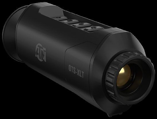
1. S A F E T Y I N S T R U C T I O N                                                       2 . S P E C I F I CAT I O N S
  These instructions are intended to ensure that the user can use the product correctly                                       OTS-XLT 160 2-8x               OTS-XLT 160 2.5-10x
to avoid danger or property loss.
                                                                                             Lens                                  19 mm                            25 mm
    Transportation
                                                                                             Sensor                                       160x120 px / 17 µm 50 Hz
    • Keep the device in original or similar packaging while transporting it.
    • Keep all wrappers after unpacking them for future use. In case of any failure, you     Magnification                         2 – 8×                          2.5 – 10×
      need to return the device to the factory with the original packaging. Transportation   Field of view, degrees               8.2×6.2                          6.5×4.9
      without the original packaging may result in damage to the device.
    • Do not drop the product or subject it to physical shock. Keep the device away from     Core                                           ATN Obsidian Core LT
      magnetic interference.                                                                 Micro Display                                       720×540 px
    Power Supply                                                                             IP rating                                              IP67
    • You will need to obtain a compatible charging block. Input voltage should meet         Charging                                            USB, type C
      the Limited Power Source (5 V DC, 2 A) according to the IEC61010-1 standard.
    • Make sure the plug is properly connected to the power socket.                          Video Record Resolution                             720×576 px
    • DO NOT connect multiple devices to one power adapter, to avoid over-heating or         Internal Storage                                       8 Gb
      fire hazards caused by overload.
                                                                                             Color modes                           White Hot / Black Hot / Red Hot / Color
    Battery
                                                                                             Battery life (Li-ion)                                 ≈10 hr
    • The built-in battery cannot be removed. Please contact the manufacture for repair
      if necessary.                                                                          Operating Temperature                     -4°F to +131°F / -20°C to 55°C
    • For long-term storage of the battery, make sure it is fully charged every half year    Dimensions                           6.85” × 2.63” × 2.08” / 174 × 67 × 53 mm
      to ensure the battery quality. Otherwise, damage may occur.
                                                                                             Weight                                            0.81 lb/370 g
    Maintenance
                                                                                             Human Detection Range, m               670                              850
    • If the product does not work properly, please contact your dealer or the nearest
      service center. We shall not assume any responsibility for problems caused by          Human Recognition Range, m             335                              425
      unauthorized repair or maintenance.                                                    Human Identification Range, m          170                              210
    • Wipe the device gently with a clean cloth and a small quantity of ethanol, if nec-
      essary.                                                                                Warranty                                              2 years
    • If the equipment is used in a manner not specified by the manufacturer, the pro-
      tection provided by the device may be impaired.
    Operational Environment
    • Make sure the operating environment meets the requirement of the device. The
                                                                                              3 . OV E R V I E W
      operating temperature shall be -20°C to 55°C (-4°F to 131°F), and the operating
      humidity shall be 95% or less.
    • DO NOT expose the device to high electromagnetic radiation or dusty environ-            3.1. BRIEF DESCRIPTION
      ments.                                                                                   The handheld thermal monocular is a handheld device for observation, high-
    • DO NOT aim the lens at the sun or any other bright light.                              est temperature target tracking, distance measurement. The high-sensitivity
    Emergency                                                                                built-in thermal detector provides you with clear view even in total darkness.
    • If smoke, odor, or noise arises from the device, immediately turn off the power,
                                                                                             The device is mainly applied to outdoor scenarios such as patrolling, law
      unplug the power cable, and contact the service center.                                enforcement, search and rescue, drug enforcement, anti-smuggling, hiking,
                                                                                             travel, and hunting, etc.

                                                                                              3.2. FUNCTION
                                                                                               Distance Measurement
                                                                                               The device can detect the distance between the target and the observation
                                                                                             position.
                                                                                               Highest Temperature Tracking
                                                                                               The device can detect the highest temperature in the scene and mark the
                                                                                             spot. This function varies according to different camera models.
4                                                                                                                                                                                  5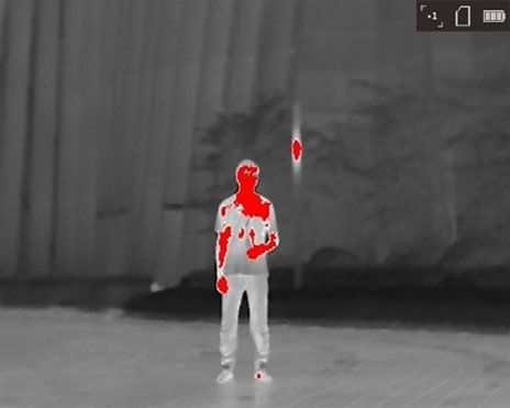
Image Correction                                                           3.3.2. Interface
  The device supports DPC (Defective Pixel Correction) and FFC/NUC (Flat
Field Correction)/(Non Uniform Correction) which can optimize the image
quality.                                                                                                             EYEPIECE

  Storage                                                                                         DIOPTER ADJUSTMENT KNOB

  The built-in memory module supports video recording and snapshot cap-
turing.

    3.3. APPEARANCE                                                                       TRIPOD SCREW

    3.3.1. Button                                                               CABLE INTERFACE

                             POWER              MODE

                                                                                                          Overview of Interfaces
                                      CAPTURE          ZOOM

                                                                             • Diopter Adjustment Knob: adjust the view of the display for your vision.
                              Buttons on the Device                          • Cable Interface: charge the device or export files with the supplied cable.
                                                                             • Tripod Screw: connect to tripod.

    Button Functions
                                                                             4 . P R E PA R AT I O N
     Icon           Button                             Function
                                                                             Take out the device and accessories. Check them with the packaging list to
                                     Press: standby mode/wake up device    confirm device and accessories are included and available for use. Read the
              Power                                                        user manual to learn the usage methods and cautions.
                                     Hold: power on/off

                                     Press: capture image                    4.1. CHARGE DEVICE
              Capture                                                        After the device starts up, the OSD (on-screen display) shows the battery
                                     Hold: recording video
                                                                           status. When the battery is low, charge the device and ensure it works properly.
                                     Press: color palettes                   Before You Start
              Mode
                                     Hold: menu                              • The charging temperature should be from 0°C to 45°C (32°F to 113°F).
                                                                             • Charge the device with the delivered cable.
                                     Press: digital zoom
              Zoom                                                           Steps
                                     Hold: FFC/NUC
                                                                             1. Lift the cable interface cover.
                                                                             2. Plug in the cable and charge the device.

6                                                                                                                                                        7
5 . I M AG E S E T T I N G S
You can set palettes, brightness, scenes, FFC/NUC (flat field correction)/
(non-uniform correction), and DPC (defective pixel correction) to display the
best image.
CABLE
INTERFACE
5.1. ADJUST DIOPTER
Make sure the eyepiece covers your eye and aim at the target. Adjust the
diopter adjustment knob until the OSD text or image is clear.
NOTE
When adjusting diopter, DO NOT touch the surface of lens to avoid
smearing the lens.
BATTERY STATUS
INDICATOR
Cable Interface
• Flashing Red & Green: error occurred.
• Solid Red: battery is properly charging.
• Solid Green: battery is fully charged.
• Off: battery is not charged.
4.2. POWER ON/OFF
Power On
When the battery is fully charged, press for 2 seconds to power on the
device.
View the Target
Power Off
When the device is turned on, hold for 2 seconds to power off the device.
4.3. MENU DESCRIPTION
When the device powers on, hold to display the menu.
Press to move the cursor up.
Press to move the cursor down. DIOPTER
ADJUSTMENT
KNOB
Press to confirm and hold it to exit the menu.
Adjust Diopter
8 95.2. FOCUS LENS 5.5. SELECT SCENE
Slightly rotate the focus wheel to focus the objective lens. Depending on the environment which you operate you can select the appro-
priate scene: ie Forest, etc.
Steps
1. Hold to go to the menu.
2. Select and press to switch scene.
• refers to recognition mode and is recommended in normal scene.
• refers to Forest mode and is recommended in hunting environment.
3. Hold to save settings and exit.
5.6. SET PALETTES
You can select different palettes to display the same scene in different
effects. Press to switch palettes.
White Hot
The hot part is light-colored in view. The higher the temperature is, the lighter
the color is.
Adjust Objective Lens
NOTE
• DO NOT touch the lens directly with your finger, or place any sharp
objects near it.
• This function varies according to different camera models.
5.3. ADJUST BRIGHTNESS
Hold , select and press to adjust brightness. In white hot mode,
the higher the value of brightness is, the brighter the image is. The image
effect in white hot mode is showed as picture below and effect in black hot Black Hot
mode is opposite. The hot part is black-colored in view. The higher the temperature is, the
darker the color is.
Adjust Brightness in White Hot Mode
5.4. ADJUST CONTRAST
Hold , select and press to adjust image contrast.
10 11Red Hot
2. Select and press to switch FFC/NUC mode.
The hot part is red-colored in view. The higher the temperature is, the redder
the color is. • Manual: Hold in live view to correct the non-uniformity of display.
• Auto: The device performs FFC/NUC automatically according to the set
schedule when switching on the camera.
• External: Cover the lens, then hold in live view to correct the non-uni-
formity of display.
3. Hold to save the settings and exit.
5.9. CORRECT DEFECTIVE PIXEL
The device can correct the defective pixels on the screen which are not per-
forming as expected.
Steps
1. Hold to show the menu.
Fusion 2. Select .
From high temperature to low temperature, the image is colored in from 3. Press to select the offset. The offset refers to the moving length of
white, yellow, red, pink to purple. cursor.
4. Press or to select the moving direction.
5. Press to move the cursor to the position of dead pixel. Hold to
correct the dead pixel.
NOTE
If the menu blocks the dead pixel, hold to perform mirror display.
6 . M E A S U R E T H E D I S TA N C E
The device can detect the distance between the target and the observation
position.
Before You Start
5.7. ADJUST DIGITAL ZOOM When measuring the distance, keep the hand and the position steady. Oth-
erwise, the accuracy may be affected.
You can zoom the image by using this function.
Steps
Press in the view mode, the live view switches between 1×, 2×, and 4×.
1. Hold to show the menu.
NOTE
2. Select and press to go to the setting interface.
This function varies according to different camera models.
a. Press or to select the target from Deer, Wolf, Bear, and
Custom.
5.8. FLAT FIELD CORRECTION / NON UNIFORM b. Set the target height.
CORRECTION
NOTE
This function can correct non-uniformity of display.
The available height ranges from 0.1 m to 9.9 m.
Steps
c. Press to confirm.
1. Hold to go to the menu.
12 133. Align the center of top mark with the top edge of the target. Press .
7. HIGHEST TEMPERATURE TRACKING
The device can detect the highest temperature spot in the scene and mark
it on display.
In the menu, select and press to mark the spot of highest tempera-
ture.
When the function is enabled, displays in the spot of highest tempera-
ture. When the scene changes, the moves.
NOTE
This function varies according to different camera models.
Set the Top Edge of the Target
The cursor blinks on the top edge of the target. 8. PICTURE AND VIDEO
4. Align the center of bottom mark with the edge of target bottom. Press . You can manually record video or capture picture when displaying live view.
8.1. CAPTURE PICTURE
On the main live view screen, press to capture picture.
NOTE
When image capture is successful, the image freezes for 1 second and
a prompt shows on the display.
For exporting captured pictures, refer to 8.4. Export Files.
8.2. RECORD VIDEO
Steps
Set the Edge of Target Bottom
Result 1. In the main live view, hold to start recording.
The left top of the image displays the distance measurement result and the
height of the target.
Start Recording
The left top of image displays the information of recording time.
Measurement Result 2. Hold again to stop recording.
NOTE What to do next
Go to distance measurement interface, and press to view the result For exporting recorded files, refer to 8.4. Export Files.
of the previous measuring target.
14 158.3. OSD 2. Select , and press . You can view the device information such as
1. Hold to display the menu. version, and serial No.
2. Select and press to switch OSD mode. 10.2. RESTORE DEVICE
When OSD (On-Screen Display) mode is enabled, the information of battery
status, storage status, and digital zoom display in top right corner of viewfinder. Steps
1. Hold to show the menu of device.
8.4. EXPORT FILES
This function is used to export recorded videos and captured pictures. 2. Select , and press to restore the device to defaults according to
the prompt.
Steps
1. Connect the device and PC with cable.
NOTE 11. FREQUENTLY ASKED QUESTIONS
Make sure the device is turned on when connecting the cable.
2. Open computer disk and select the disk of device. Go to DICM →
11.1. WHY DOES THE CHARGE INDICATOR
100EZVIZ. FLASH IMPROPERLY?
3. Select and copy the files to PC. Check the following items.
4. Disconnect the device from your PC.
1. Check whether the device is charged with standard power adapter and
NOTE the charging temperature is above 0°C (32°F).
• The device displays images when you connect it to PC. But functions 2. The device is equipped with built-in charging protection module. Charge
such as recording, capturing are disabled. the device in power off status.
• When you connect the device to PC for the first time, it installs the
drive program automatically. 11.2. THE IMAGE IS NOT CLEAR, HOW TO
ADJUST IT?
9. CVBS OUTPUT Adjust the diopter adjustment knob until the image is clear. And or adjust the
You can view the image on the display unit for details with this function. Front Focus to clear up the image. Refer to section Adjust Diopter or Focus Lens.
Before You Start 11.3. CAPTURING OR RECORDING FAILS.
Purchase the CVBS cable from the manufacturer separately or prepare it by
yourself. WHAT’S THE PROBLEM?
Connect the device and the display unit via USB to CVBS cable. Check the following items.
Turn on the device so that it can be detected by the display when activated. • Whether the device is connected to your PC. Capturing or recording is
disabled in this status.
Steps
• Whether the storage space is full.
1. Hold to show the menu of device. • Whether the device has low-battery.
2. Select , and press to turn on output.
The display unit shows the device image. 11.4. WHY THE PC CANNOT IDENTIFY THE
DEVICE?
10 . M A I N T E N A N C E Check the following items.
• Whether the device is connected to your PC with supplied USB cable.
This section provides information on checking the device information and
restoring to defaults. • If you use other USB cables, make sure the cable length is no longer
than 1 m.
10.1. VIEW DEVICE INFORMATION
Steps
1. Hold to show the menu of device.
16 1712 . WA R N I N G S A N D CAU T I O N S LIMITATION OF LIABILITY
ATN will not be liable for any claims, actions, suits, proceedings, costs,
• Always remember to turn off the device when it is not in use. expenses, damages or liabilities arising out of the use of this product. Opera-
• Do not disassemble, drop, open, crush, bend, deform, puncture, shred, tion and use of the product are the sole responsibility of the Customer. ATN’s
microwave, incinerate, paint or insert foreign objects: it will void your war- sole undertaking is limited to providing the products and services outlined
ranty. herein in accordance with the terms and conditions of this Agreement. The
• Keep the monocular in the provided protective cover when not in use. provision of products sold and services performed by ATN to the Customer
shall not be interpreted, construed, or regarded, either expressly or implied, as
• Avoid contact with dust, steam, and gas. being for the benefit of or creating any obligation toward any third party of legal
• This product contains natural rubber latex which may cause allergic reac- entity outside ATN and the Customer; ATN’s obligations under this Agreement
tions. extend solely to the Customer. ATN’s liability hereunder for damages, regard-
• The monocular is a precision electro-optical instrument and must be han- less of the form or action, shall not exceed the fees or other charges paid to
dled carefully. ATN by the customer or customer’s dealer. ATN shall not, in any event, be
• Do not scratch the external lens surfaces or touch them with your fingers. liable for special, indirect, incidental, or consequential damages, including, but
not limited to, lost income, lost revenue, or lost profit, whether such damages
CAUTION were foreseeable or not at the time of purchase, and whether or not such dam-
Failure to follow these safety instructions could result in damage to the ages arise out of a breach of warranty, a breach of agreement, negligence,
device! strict liability or any other theory of liability.
PRODUCT WARRANTY REGISTRATION
13 . 2 Y E A R P R O D U C T WA R R A N T Y In order to validate the warranty on your product, ATN must receive a com-
pleted Product Warranty Registration Card for each unit or complete war-
This product is guaranteed to be free from manufacturing defects in material ranty registration on our website at www.atncorp.com. Please complete the
and workmanship under normal use for a period of 2 (two) years from the date included form and immediately mail it to our Service Center: ATN Corporation,
of purchase. In the event a defect that is covered by the foregoing warranty 1341 San Mateo Avenue, South San Francisco, CA 94080.
occurs during the applicable period stated above, ATN, at its option, will either
repair or replace the product, and such action on the part of ATN shall be the OBTAINING WARRANTY SERVICE
full extent of ATN’s liability, and the Customer’s sole and exclusive remedy. To obtain warranty service on your unit, End-user must notify ATN service
This warranty does not cover a product (a) used in other than its normal and department by calling 800-910-2862 or 650-989-5100 or via e-mail service@
customary manner; (b) subjected to misuse; (c) subjected to alterations, mod- atncorp.com to receive a Return Merchandise Authorization number (RMA).
ifications or repairs by the Customer or by any party other than ATN without When returning please take or send the product, postage paid, with a copy
prior written consent of ATN; (d) special order or “close-out” merchandise or of your sales receipt to our service center, ATN Corporation at the address
merchandise sold “as-is” by either ATN or the ATN dealer; or (e) merchandise noted above. All merchandise must be fully insured with the correct postage;
that has been discontinued by the manufacturer and either parts or replace- ATN will not be responsible for improper postage or, missing or damaged mer-
ment units are not available due to reasons beyond the control of ATN. ATN chandise during shipment.
shall not be responsible for any defects or damage that in ATN’s opinion is When sending product back, please clearly mark the RMA# on the outside
a result from the mishandling, abuse, misuse, improper storage or improper of the shipping box. Please include a letter that indicates your RMA#, Name,
operation, including use in conjunction with equipment which is electrically Return Address, reason for service return, Contact information such as valid
or mechanically incompatible with or of inferior quality to the product, as well telephone numbers and/or e-mail address and proof of purchases that will
as failure to maintain the environmental conditions specified by the manufac- help us to establish the valid start date of the warranty. Product merchandise
turer. This warranty is extended only to the original purchaser. Any breach of returns that do not have an RMA listed may be refused or a significant delay in
this warranty shall be waived unless the customer notifies ATN at the address processing may occur.
noted below within the applicable warranty period. Estimated Warranty service time is 10-20 business days. End-user/cus-
The customer understands and agrees that except for the foregoing war- tomer is responsible for postage to ATN for warranty service. ATN will cover
ranty, no other warranties written or oral, statutory, expressed or implied, return postage/shipping to continental USA end-users/customers after war-
including any implied warranty of merchantability or fitness for a particular ranty repair only if product is covered by aforementioned warranty. ATN will
purpose, shall apply to the product. All such implied warranties are hereby and return product after warranty service by domestic UPS ground and/or domes-
expressly disclaimed. tic mail. Any other requested, required or international shipping method the
postage/shipping fee will be the responsibility of the end-user/customer.
18 19For customer service and technical support, please contact
American Technologies Network Corp.
2400 NW 95th Ave, Doral, FL 33172
phone: 800-910-2862, 650-989-5100
e-mail: service@atncorp.com
www.atncorp.com
©2021 ATN CorporationYou can also read