Artisan AR7300-8001 M Silver - PRE-COLORED FORMULATION - Avient
←
→
Page content transcription
If your browser does not render page correctly, please read the page content below

PROCESSING GUIDE

                              Artisan™
                   AR7300-8001 M Silver
                      PRE-COLORED FORMULATION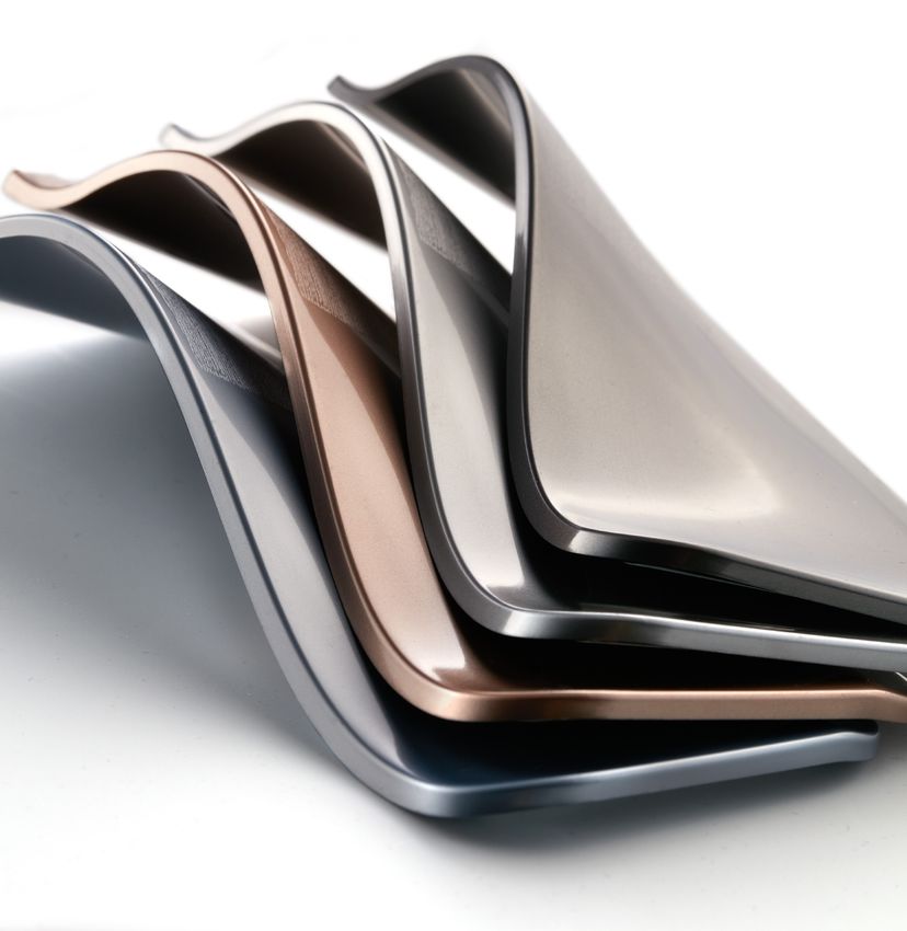
Artisan™ Pre-Colored Thermoplastics
Artisan™ AR7300-8001 M Silver pre-colored thermoplastics are customized ABS formulations to help
manufacturers achieve brilliant and high-gloss metallic effect, excellent chemical resistance, and scratch
resistance. Compared with a traditional painting process, injection-molded Artisan materials also offer
additional sustainable benefits: energy use and VOC emissions are reduced by eliminating secondary
painting or in-mold labeling. These materials can be widely applied in consumer electronics applications
with high performance requirements.

                     BASE RESIN                                                 ABS

                  Drying Temperature                                          80–90°C

                      Drying Time                                            2–3 Hours

   Barrel Temperatures °C

                      Rear Zone                                               550–580

                     Center Zone                                              560–600

                      Front Zone                                              580–620

                        Nozzle                                                575–615

                   Mold Temperature                                            50–80

                      Screw Speed                                             Moderate

                     Back Pressure                                            3–10 bar

                        Cushion                                               5–15 mm

                    Injection Speed                                        Low to Medium

                   Injection Pressure                                     Moderate to High

                    Holding Pressure                                10–30% of Injection Pressure

                      Screw Type                                          General purpose

                       Screw L/D                                                20:1

               Screw Compression Ratio                                       2.0:1–2.5:1

                Non-return Check Valve                                  Free Flow Check Ring

                      Nozzle Type                                          Reverse Taper

                    Barrel Capacity                                30–80% of barrel should be used
STARTUP & SHUTDOWN   RECOMMENDATIONS

                     2–3 melt flow PP or purging compound. HDPE is not recommended for purging
  Purge Compound
                     as it can cause delamination or lead to black specks.

                     Regrind is not suggested. Can cause issues with color variation, surface defects,
      Regrind
                     loss of properties and may affect the weatherability.

   MOLD DESIGN       RECOMMENDATIONS

                     • Many different types of gates can be used, such as fan, tunnel, tab,
                       and edge gates.
       Gates         • Moderate gate size according to the part geometry. Gate thickness should be
                       50–75% of wall thickness.
                     • Avoid gating into thin part region.

                     • Full-round runners or modified trapezoid runners are the best designs.
                     • Half-round runners are not recommended.
                     • Only naturally balanced runner systems (“H” pattern) are recommended.
                     • Runner diameters should not be less than the part thickness.
      Runners
                     • Runner diameter should be 1.5x the part thickness.
                     • Step each 90° bend in the system down in size.
                     • Place vents at each 90° intersection and vent to atmosphere.
                     • Hot runner molds are acceptable and should be sized by the manufacturer.

                     • Place these wells at the base of the sprue to capture the cold material first
                       emerging from the nozzle.
   Cold Slug Wells   • Place wells at every 90° bend in the runner system.
                     • Well depths approximately 2.5 times the diameter of the runner provide
                       the best results.

                     • Place vents at the end of fill and anywhere potential knit/weld lines will occur.
                     • All vents need to be vented to atmosphere.
      Venting
                     • For circular parts, full perimeter venting is recommended.
                     • Cut vent depths to 0.0007″–0.0015″.

     Draft Angle     • Maintain a minimum draft angle of 1° per side.
TROUBLESHOOTING RECOMMENDATIONS
PROBLEM CAUSE SOLUTION
• Increase nozzle and barrel temperatures
Melt and/or mold • Increase mold temperature
temperature too cold • Increase injection rate
• Check thermocouples and heater bands
• Increase shot size
Shot size • Adjust transfer position to 98% full
• Increase cushion
Incomplete Fill
• Enlarge or widen vents and increase number of vents
• Check that vents are unplugged
• Check that gates are unplugged
Mold design • Enlarge gates and/or runners
• Perform short shots to determine fill pattern and verify
proper vent location
• Increase wall thickness to move gas trap to parting line
• Decrease melt temperature
Degraded/overheated • Decrease back pressure
material • Use smaller barrel
• Decrease injection speed
• Relocate gate to non-stress area
Brittleness Gate location
• Increase gate size to allow higher flow rate and lower
and/or size
molded-in stress
• Check moisture. If material is not in the
Wet material recommended moisture percentage for molding, dry
material until it is in the acceptable range for molding.
• Increase melt temperature
Melt temperature
• Increase mold temperature
too low
• Increase injection speed
Fibers on Surface
(Splay)
• Check moisture. If material is not in the recommended
Wet material moisture percentage for molding, dry material until
it is in the acceptable range for molding.
• Decrease nozzle and barrel temperatures
Melt too hot
• Decrease mold temperature
• Adjust transfer position
Insufficient • Increase shot size
Sink Marks
material volume • Increase injection rate
• Increase packing pressure
Part geometry • Reduce wall thickness
too thick • Reduce rib thicknessTROUBLESHOOTING RECOMMENDATIONS
PROBLEM CAUSE SOLUTION
• Decrease injection pressure
Injection pressure • Increase clamp pressure
too high • Decrease injection rate
• Increase transfer position
• Adjust transfer position
Excess • Decrease pack pressure
Flash material volume • Decrease shot size
• Decrease injection rate
Melt and/or mold • Decrease nozzle and barrel temperatures
temperature too hot • Decrease mold temperature
• Reset mold height
Loose clamp
• Increase clamp tonnage
• Increase cooling time
Too much shrink
• Decrease mold temperature
Shrink
• Decrease cooling time
Too little shrink
• Increase mold temperature
• Decrease nozzle and barrel temperatures
• Decrease mold temperature
Process related
• Decrease injection rate
• Reduce decompression
Burning
• Clean, widen and increase number of vents
Mold design
• Increase gate size to reduce shear
Wet material • Verify material is dried at proper condition
• Decrease nozzle temperature
Nozzle temperature • Decrease back pressure
too hot • Increase screw decompression
Nozzle Drool • Verify material has been dried at proper conditions
Incorrect nozzle • Use reverse taper tip
• Increase injection rate
Melt front
• Increase pack and hold pressure
temperatures are
• Increase melt temperature
too low
• Increase mold temperature
Weld Lines
• Increase gate size
• Identify end of fill pattern and verify proper
Mold design vent location
• Add vents or increase vent width
• Move gate locationTROUBLESHOOTING RECOMMENDATIONS
PROBLEM CAUSE SOLUTION
• Increase melt temperature
• Reduce injection speed
• Increase pack pressure
Process related
• Increase pack time
• Decrease mold temperature
• Increase cool time
Warp
Mold design • Non-uniform mold cooling
Part design • Non-uniform wall thickness
Thermolator incorrect • Check settings
temperature • Inspect thermocouple
• Decrease injection rate and pressure
• Decrease hold pressure
• Adjust transfer position
Overfilled cavity
• Decrease nozzle and barrel temperatures
• Decrease mold temperature
• Decrease cooling time
Sticking in Mold
• Decrease barrel temperature
Part too hot • Decrease mold temperature
• Increase cooling time
• Increase draft angle
Mold design
• Polish cores in direction of ejection
Contamination • Purge machine
• Reduce melt temperature
Black Specks Degradation • Reduce screw speed
• Reduce back pressure
Machine related • Check for wear on screw, barrel or check ring
• Increase melt temperature
Process related • Decrease injection speed
• Purge barrel to eliminate material contamination
Delamination
• Reduce sharp corners in material flow path
Mold design
• Increase ventingTROUBLESHOOTING RECOMMENDATIONS
PROBLEM CAUSE SOLUTION
• Decrease melt temperature
Oversheared material • Decrease injection speed
• Reduce residence time
Discoloration
Mold design • Increase gate sizing
• Check moisture of material to ensure it is within the
Dry material
recommended moisture percentage for molding1.844.4AVIENT www.avient.com Copyright © 2020, Avient Corporation. Avient makes no representations, guarantees, or warranties of any kind with respect to the information contained in this document about its accuracy, suitability for particular applications, or the results obtained or obtainable using the information. Some of the information arises from laboratory work with small-scale equipment which may not provide a reliable indication of performance or properties obtained or obtainable on larger-scale equipment. Values reported as “typical” or stated without a range do not state minimum or maximum properties; consult your sales representative for property ranges and min/max specifications. Processing conditions can cause material properties to shift from the values stated in the information. Avient makes no warranties or guarantees respecting suitability of either Avient’s products or the information for your process or end-use application. You have the responsibility to conduct full-scale end-product performance testing to determine suitability in your application, and you assume all risk and liability arising from your use of the information and/or use or handling of any product. AVIENT MAKES NO WARRANTIES, EXPRESS OR IMPLIED, INCLUDING, BUT NOT LIMITED TO, IMPLIED WARRANTIES OF MERCHANTABILITY AND FITNESS FOR A PARTICULAR PURPOSE, either with respect to the information or products reflected by the information. This literature shall NOT operate as permission, recommendation, or inducement to practice any patented invention without permission of the patent owner.
You can also read