APCO CVS-6000/6000A SWING CHECK VALVES WITH AIR CUSHION CYLINDER, OIL CONTROLLED CYLINDER AND OIL CONTROLLED BOTTOM MOUNTED BUFFER - DEZURIK
←
→
Page content transcription
If your browser does not render page correctly, please read the page content below
APCO CVS-6000/6000A Swing
     Check Valves with Air Cushion
    Cylinder, Oil Controlled Cylinder
          and Oil Controlled Bottom
                     Mounted Buffer

                                                                                   Instruction D12006
                                                                                               January 2022

DeZURIK, Inc. Sartell, Minnesota USA | Phone: 320-259-2000 | www.dezurik.com | info@dezurik.com
DeZURIK
APCO CVS-6000/6000A Swing Check Valves with Air Cushion Cylinder, Oil Controlled Cylinder and Oil
Controlled Bottom Mounted Buffer

Instructions
These instructions provide installation, operation and maintenance information for APCO CVS-6000/6000A
Swing Check Valves with Air Cushion Cylinder (AC), Oil Controlled Side Mounted Cylinder (OC) and Oil
Controlled Bottom Mounted Buffer (BMB). They are intended to be used by personnel who are responsible for
installation, operation and maintenance of APCO CVS-6000/6000A Swing Check Valves.

Safety Messages
All safety messages in the instructions are flagged with an exclamation symbol and the word Notice or
Warning. These messages indicate procedures that must be followed exactly to avoid equipment damage,
personal injury or death.
Safety label(s) on the product indicate hazards that can cause equipment damage, personal injury or death. If
a safety label becomes difficult to see or read, or if a label has been removed, please contact DeZURIK for
replacement label(s).

 Personnel involved in the installation or maintenance of valves should be constantly alert to
 potential emission of pipeline material and take appropriate safety precautions. Always wear suitable
 protection when dealing with hazardous pipeline materials. Handle valves, which have been removed
 from service with suitable protection for any potential pipeline material in the valve.

Inspection
Your APCO CVS-6000/6000A Swing Check Valve has been packaged to provide protection during shipment;
however, it can be damaged in transport. Carefully inspect the unit for damage upon arrival and file a claim
with the carrier if damage is apparent.

Parts
Recommended spare parts are listed on the assembly drawing. These parts should be stocked to minimize
downtime. Order parts from your local DeZURIK sales representative, or directly from DeZURIK. When
ordering parts please provide the following information:
If the valve has a DeZURIK APCO nameplate please include the 7-digit part number and 4-digit revision
number (example: 9999999R000) located on the data plate attached to the valve assembly. Also include the
part name, the assembly drawing number, the balloon number and the quantity stated on the assembly
drawing.
If there isn't any nameplate visible on the valve, please include valve model number, part name, and item
number from the assembly drawing. You may contact your local DeZURIK APCO Representative to help
identify your valve.

DeZURIK Service
DeZURIK service personnel are available to maintain and repair all DeZURIK products. DeZURIK also offers
customized training programs and consultation services. For more information, contact your local DeZURIK
sales representative or visit our website at www.dezurik.com.

January 2022                                    Page 2                                         D12006
DeZURIK
APCO CVS-6000/6000A Swing Check Valves with Air Cushion Cylinder, Oil Controlled Cylinder and Oil
Controlled Bottom Mounted Buffer
Table of Contents
Description ........................................................................................................................................................ 4
Handling and Storage ........................................................................................................................................ 4
Installation ......................................................................................................................................................... 4
Fusion/Powder Coated Valves........................................................................................................................... 5
Maintenance ...................................................................................................................................................... 5
  CVS-6000/6000A valves with AC and OC ..................................................................................................... 5
  Figure 1 – Lubrication of Cylinder .................................................................................................................. 5
  CVS-6000/6000A Valves with BMB ............................................................................................................... 5
  Disassembly Procedure ................................................................................................................................. 6
  Assembly Procedure...................................................................................................................................... 7
Drawings ........................................................................................................................................................... 8
  Figure 2 – Valve Assembly ............................................................................................................................ 8
  Table 2 : Figure 2 Parts Identification............................................................................................................. 9
  Figure 3 – Valve Assembly with BMB .......................................................................................................... 10
  Table 3: Figure 3 Parts Identification............................................................................................................ 11
  Figure 4 – Valve Assembly with OC ............................................................................................................. 12
  Table 4: Figure 4 Parts Identification............................................................................................................ 13
  Figure 5 – Valve Assembly with AC ............................................................................................................. 14
  Table 5: Figure 5 Parts Identification............................................................................................................ 15
Operation ........................................................................................................................................................ 16
  CVS-6000-AC Valves Start-up Procedure ................................................................................................... 16
  CVS-6000-OC Valves Start-up Procedure ................................................................................................... 17
  CVS-6000-BMB Valves Start-up Procedure ................................................................................................. 18
  Start-up Procedure ...................................................................................................................................... 18
  Table 6: Maximum Stroke Length of Buffer Rod .......................................................................................... 18
  Start-up Procedure (cont.) ........................................................................................................................... 19
  Closing Speed Adjustment........................................................................................................................... 19
Adjustment of Flow Control Valve .................................................................................................................... 20
  Figure 6 – Flow Control Valve ...................................................................................................................... 20
Operation of Internal Cushion .......................................................................................................................... 20
  Figure 7 – Cushion “IN” Stroke .................................................................................................................... 20
  Figure 8 – Cushion “OUT” Stroke ................................................................................................................ 20
Timing Valve Adjustment (CVS-6000-OC Valves) ........................................................................................... 21
  Figure 9 – Timing Valve ............................................................................................................................... 21
Oil Filling Procedure ........................................................................................................................................ 22
  CVS-6000-OC Valves .................................................................................................................................. 22
  CVS-6000-BMB Valves ............................................................................................................................... 22
Troubleshooting ............................................................................................................................................... 23

January 2022                                                             Page 3                                                                 D12006
DeZURIK
APCO CVS-6000/6000A Swing Check Valves with Air Cushion Cylinder, Oil Controlled Cylinder and Oil
Controlled Bottom Mounted Buffer

Description
A swing check valve consists of a valve body, a bonnet, and a disc that is connected to a hinge. The disc
swings away from the valve seat to allow flow in the forward direction, and returns to the valve seat when
upstream flow is stopped to prevent backflow.
The flow from the pump opens the disc and raises the counterweight. When the pump is shut off, the disc
closes and is held closed by downstream static pressure. The CVS-6000/6000A valve can be equipped with a
weighted counterweight arm and an Air Cushion Cylinder (AC), Oil Controlled Side Mounted Cylinder (OC) or
an Oil Controlled Bottom Mounted Buffer (BMB) to control valve closure.

Handling and Storage
Lifting the valve improperly may damage it. Do not fasten lifting devices to the cylinder or through the seat
opening in the body. Lift the valve with slings, chains or cables fastened around the valve body, or fastened to
bolts or rods through bolt holes in the flanges.
If installation will be delayed, place valve indoors in secure, weather tight storage. If temporary outside storage
is unavoidable, make sure a vermin proof rain cover (water shedding tarp, etc.) is secured around/over the
valve to keep off rain and mud. Skid and set the assembly on a flat, solid, and well drained surface for
protection from ground moisture, runoff and pooled rain water.

Installation
   •   See figures 2 through 5 for part identification.
   •   Turbulent flow entering into the valve may cause excessive disc motion and wear of the internal
       components. It is recommended that CVS 6000/6000A valves be located at least three pipe diameters
       away from turbulence producers such as pumps, elbows, reducers, and control valves.
   •   When installed in vertical position, the valve shaft must be perpendicular to the incoming horizontal
       pipe.
   •   For valves with BMB or OC, the Oil Reservoir (B58) and for BMB only, the Hydro-Pneumatic
       Accumulator (B73) must be mounted vertically regardless of the valve installation position.
   •   Before installation, remove foreign material such as weld spatter, oil, grease, and dirt from the pipeline.
   •   Prepare pipe ends and install valves in accordance with the pipe manufacturer’s instructions for the
       joint used.

 Do not deflect the pipe-valve joint. Minimize bending stresses in the valve end connection with pipe
 loading.
 If excessive seat leakage occurs during start-up, recheck the installation and eliminate any distortion
 to the valve body.

   •   Ensure the valve and pipeline flanges are concentric to ensure proper flange sealing.
   •   Tighten the flange bolts or studs in a crisscross pattern in a minimum of four stages.

January 2022                                      Page 4                                           D12006
DeZURIK
APCO CVS-6000/6000A Swing Check Valves with Air Cushion Cylinder, Oil Controlled Cylinder and Oil
Controlled Bottom Mounted Buffer
Fusion/Powder Coated Valves
Valves with fusion/powder coated exterior paint require flat washers to be installed under the flange
nuts when installing the valve to the pipeline flange to prevent the paint from cracking or chipping.
Maintenance
CVS-6000/6000A valves with AC and OC
A periodic (approximately 6 months) lubrication of the cylinder lever pin and eye bracket pin to keep the valve
in good operating condition. For the Air Cushion Cylinder, a few drops of oil should be applied to the top and
bottom ports of the cylinder by removing the breather caps. Recommended lubricants: SAE 10W/20, WD 40.
Figure 1 – Lubrication of Cylinder
CVS-6000/6000A Valves with BMB
A periodic (approximately 6 months) lubrication of the exposed area of Buffer Rod (B84) is required to keep the
valve in good operating condition.
Through the course of normal operation, the Hydro-pneumatic Accumulator (B73) must be checked for loss of
pressure. It is normal for the Pressure Gauge (B74) to indicate a decrease in pressure when the valve opens
due to the transfer of oil from the accumulator to the cylinder. See figure 3 for parts identification.
Special care should be taken on the exposed area of the buffer rod if repainting the valve is required. It should
be fully masked to prevent even a small amount of paint getting on the buffer rod. This could damage the
cylinder rod seal and cause the cylinder to leak.
January 2022 Page 5 D12006DeZURIK
APCO CVS-6000/6000A Swing Check Valves with Air Cushion Cylinder, Oil Controlled Cylinder and Oil
Controlled Bottom Mounted Buffer
Disassembly Procedure
See Figures 2 through 5 for part identification.
These valves may open or close, swinging the Counterweight/spring loaded arm without warning
due to flow changes from pumps starting and stopping. Servicing or working around these valves
while the pipeline is under pressure can cause personal injury or equipment damage.
Workers must be cautious when working around these valves.
Relieve pipeline pressure and lockout the pumps before servicing the valve.
1. Relieve the pressure in the pipeline.
Servicing the valve while the pipeline is under pressure can cause personal injury or equipment
damage. Relieve pipeline pressure before servicing the valve.
2. If it is necessary to remove valve from pipeline, set valve standing on its inlet flange.
3. Support Counterweight Arm (B28), then unscrew Set Screw (B36) and remove Counterweight (B19).
4. Loosen Lever Arm Bolt/Set Screw (B55) holding Lever Arm (B19) to Pivot Shaft (A13) and remove
Counterweight Arm assembly (B19 and B28)
5. Valves equipped with AC or OC only:
a. Disconnect the pin between Cushion Lever (B27) and Pneumatic Cylinder (B20).
b. Unscrew Eye Bracket Mounting Bolts (B25) to remove Pneumatic Cylinder (B20).
c. Loosen Cushion Lever Set Screw (B35) to remove Cushion Lever (B27).
6. Remove Cover (A02) by unscrewing Cover Bolts (A04).
7. Unscrew Disc Arm Set screws (A14).
8. Remove Pivot Shaft Cover (A15) and Pivot Shaft Seal Retainer (A37) at both ends of the pivot shaft.
9. Pull Pivot Shaft (A13) from the right side of the valve (facing inlet).
10. Remove Pivot Shaft Flanged Bushing (A12), Pivot Shaft Key (A33), Pivot Shaft Seal (A17) and Pivot
Shaft Cover Seal (A18).
11. Remove Disc Pin Retainers (A41) and pull out Disc Pins (A08).
12. Pull out Disc Arm (A09) and Disc (A10).
13. Remove Disc Seat (A06) and Seat Retaining Ring (A31) by unscrewing all Seat Retaining Screws
(A32).
14. Unscrew the Body Seat Retaining Set Screws (A40) located in the Body Seat Ring (A05).
15. Evenly pry the Body Seat Ring (A05) out of the Body (A01).
January 2022 Page 6 D12006DeZURIK
APCO CVS-6000/6000A Swing Check Valves with Air Cushion Cylinder, Oil Controlled Cylinder and Oil
Controlled Bottom Mounted Buffer
Assembly Procedure
See Figures 2 through 5 for part identification.
1. If valve is removed from pipeline, set body standing on its inlet flange.
2. Install Body Seat Seal (A43) in the groove of Body Seat Ring (A05).
3. Install Body Seat Ring (A05) evenly inside the counterbore of the Body (A01) until it bottoms out.
4. Screw and tighten the Body Seat Retaining Set Screws (A40) into the Body Seat Ring (A05).
5. Set Disc (A10) with seat side up, install Disc Seat (A06) and Seat Retaining Ring (A31) and fasten with
Seat Retaining Screws (A32).
6. Connect Disc Arm (A09) assembly to Disc (A10) by inserting Disc Pins (A08) and secure with Disc Pin
Retainers (A41).
7. Set Disc (A10) and Disc Arm (A09) assembly on top of Body Seat Seal (A43).
8. Slip the Pivot Shaft Flanged Bushing (A12) on the Pivot Shaft (A13) with the flanged side against the
Pivot Shaft Collar (A60).
9. Insert Pivot Shaft Key (A33) in keyway on Pivot Shaft (A13).
10. Install Pivot Shaft (A13) from right side of Body (A01) through Disc Arm (A09) until Pivot Shaft Collar
(A60) is flush with Body (A01).
11. Insert Pivot Shaft Straight Bushing (A11) into the Body (A01) at the other end.
12. Insert Pivot Shaft Seal (A17) and Pivot Shaft Cover Seal (A18) in their respective grooves.
13. Insert Pivot Shaft Seal Retainer (A37) on Pivot Shaft Cover (A15) and install on both ends of Pivot
Shaft (A13). Install Pivot Shaft Cover Bolts (A16).
14. Install Cover Seal (A03) and Cover (A02), then fasten with Cover Bolts (A04).
15. Valves equipped with AC or OC:
a. Insert Cushion Lever Key (B34) on the Pivot Shaft (A13) and position Cushion Lever (B27) in
line with Pneumatic Cylinder (B20) and tighten Cushion Lever Set Screw (B35).
b. Connect Cushion Lever (B27) to Pneumatic Cylinder (B20).
16. Insert Lever Arm Key (B49) on Pivot Shaft (A13) if provided and slip Counterweight Arm assembly (B19
and B28) in place. Set arm at an angle approximately 25º - 30º below horizontal axis and secure with
Lever Arm Bolts (B55) and Lever Arm Nuts (B56).
17. Install Counterweight (B29) at desired setting and secure with Counterweight Set Screws (B36).
January 2022 Page 7 D12006DeZURIK
APCO CVS-6000/6000A Swing Check Valves with Air Cushion Cylinder, Oil Controlled Cylinder and Oil
Controlled Bottom Mounted Buffer
Drawings
Figure 2 – Valve Assembly
January 2022 Page 8 D12006DeZURIK
APCO CVS-6000/6000A Swing Check Valves with Air Cushion Cylinder, Oil Controlled Cylinder and Oil
Controlled Bottom Mounted Buffer
Table 2 : Figure 2 Parts Identification
A01 BODY
A02 COVER
A03 COVER SEAL
A04 COVER BOLTS
A05 BODY SEAT RING
A06 DISC SEAT
A07 DISC STOP
A08 DISC PIN
A09 DISC ARM
A10 DISC
A11 PIVOT SHAFT STRAIGHT BUSHING
A12 PIVOT SHAFT FLANGED BUSHING (ALL EXCEPT 42”)
A12 SPACER (42” ONLY)
A13 PIVOT SHAFT
A14 DISC ARM SET SCREW
A15 PIVOT SHAFT COVER
A16 PIVOT SHAFT COVER BOLT
A17 PIVOT SHAFT SEAL
A18 PIVOT SHAFT COVER SEAL
A31 SEAT RETAINING RING
A32 SEAT RETAINING SCREW
A33 PIVOT SHAFT KEY
A37 PIVOT SHAFT SEAL RETAINER
A39 DISC STOP LOCKNUT
A40 BODY SEAT RETAINING SET SCREW
A41 DISC PIN RETAINER
A42 COVER PIPE PLUG
A43 BODY SEAT SEAL
A53 PIVOT SLEEVE BEARING
A57 DISC ARM SLEEVE
A60 PIVOT SHAFT COLLAR (NOTE 2)
A61 PIVOT SHAFT SET SCREW (NOTE 2)
A65 COVER NUT
A66 DATA PLATE
A67 DRIVE SCREW
A90 BODY PIPE PLUG
A91 DISC RING SEAL
A92 BMB PLUG (NOTE 1)
A93 BMB PLUG SEAL (NOTE 1)
A95 BMB PLUG RETAINING SCREW (NOTE 1)
A96 COVER BOLT WASHER
A97 PIVOT SHAFT COVER WASHER
A98 BMB COVER WASHER (NOTE 1)
A99 DISC STOP WASHER
NOTES: 1. BMB PLUG NOT INCLUDED FOR VALVES WITH BMB CLOSURE CONTROL
2. VALVE SIZES 2-3”, 16-54” & 66” HAVE A SINGLE PIECE, WELDED PIVOT SHAFT
January 2022 Page 9 D12006DeZURIK
APCO CVS-6000/6000A Swing Check Valves with Air Cushion Cylinder, Oil Controlled Cylinder and Oil
Controlled Bottom Mounted Buffer
Figure 3 – Valve Assembly with BMB
January 2022 Page 10 D12006DeZURIK
APCO CVS-6000/6000A Swing Check Valves with Air Cushion Cylinder, Oil Controlled Cylinder and Oil
Controlled Bottom Mounted Buffer
Table 3: Figure 3 Parts Identification
A00 VALVE ASSEMBLY
B03 STREET ELBOW
B04 HOSE
B05 CLOSE NIPPLE
B06 ELBOW – 3000 PSI
B08 REDUCER (TO CYLINDER PORTS, NOT SHOWN)
B10 NIPPLE
B11 NIPPLE
B12 PIPE PLUG
B13 TANK VALVE
B14 AIR BREATHER (NOTE 1)
B19 LEVER ARM
B20 PNEUMATIC CYLINDER
B28 COUNTERWEIGHT ARM
B29 COUNTERWEIGHT
B30 FLOW CONTROL VALVE (NOTE 2)
B36 SET SCREW
B49 LEVER ARM KEY
B54 NUT
B55 LEVER ARM BOLT/SET SCREW
B56 CYLINDER SPACER
B57 WASHER
B58 OIL RESERVOIR
B60 SPLIT SHAFT COLLAR
B61 BUFFER ROD STOP
B62 BUFFER ROD STOP SET SCREW
B65 CYLINDER ROD COUPLER
B66 CYLINDER ROD ADAPTOR
B69 CYLINDER MTG. BOLT
B71 BUFFER ROD SEAL
B72 HYDRO PNEUMATIC ACCUMULATOR MTG. BOLT
B73 HYDRO PNEUMATIC ACCUMULATOR
B74 PRESSURE GAUGE
B76 BUFFER ROD BUSHING
B77 BUSHING SEAL
B78 BUFFER ROD BUSHING RET. RING
B79 RETAINING RING SCREW
B81 BUFFER ROD SEAL BACK-UP
B84 BUFFER ROD
B89 CYLINDER SPACER SEAL
B90 WASHER
B91 CYLINDER SPACER MTG. BOLT
B96 BUFFER ROD SCRAPER
B97 SET SCREW
B98 WASHER
B99 WASHER
NOTES 1. DO NOT SHIP WITH AIR BREATHER (B14) INSTALLED. INSTALL PIPE PLUG (B12)
INSTEAD
2. FLOW CONTROL VALVE (B30) IS TO BE INSTALLED SO THAT FLOW IS
CONTROLLED FLOWING OUT OF THE CYLINDER AND FREE FLOW TOWARDS
THE CYLINDER.
3. VALVE SIZES 14” & LARGER HAVE TWO COUNTERWEIGHT ASSEMBLIES (B19,
B28 and B29), ONE ON EITHER SIDE OF THE VALVE.
January 2022 Page 11 D12006DeZURIK
APCO CVS-6000/6000A Swing Check Valves with Air Cushion Cylinder, Oil Controlled Cylinder and Oil
Controlled Bottom Mounted Buffer
Figure 4 – Valve Assembly with OC
January 2022 Page 12 D12006DeZURIK
APCO CVS-6000/6000A Swing Check Valves with Air Cushion Cylinder, Oil Controlled Cylinder and Oil
Controlled Bottom Mounted Buffer
Table 4: Figure 4 Parts Identification
B01 NIPPLE
B02 TEE
B03 NIPPLE
B04 PIPE PLUE
B05 TEE
B06 REDUCING BUSHING (SEE NOTE 3)
B07 CROSS
B08 NIPPLE
B09 HOSE
B10 TEE
B11 NIPPLE
B12 HOSE
B13 CROSS
B14 HOSE
B15 TIMING VALVE SCREW
B16 TIMING VALVE NUT
B17 HOSE
B18 NIPPLE
B19 COUNTERWEIGHT LEVER ARM
B20 PNEUMATIC CYLINDER
B21 CYLINDER BRACKET MOUNTING BOLT
B22 UNION
B23 PIPE PLUG
B24 CYLINDER BRACKET
B25 CYLINDER BRACKET MOUNTING BOLT
B26 CYLINDER BRACKET MOUNTING NUT
B27 CYLINDER LEVER
B28 COUNTERWEIGHT ARM
B29 COUNTERWEIGHT
B30 FLOW CONTROL VALVE
B31 ELBOW
B32 NIPPLE
B33 TIMING VALVE CAM DIAL
B34 CUSHION LEVER KEY
B35 CUSHION LEVER SET SCREW
B36 COUNTERWEIGHT SET SCREW
B37 DRIVE SCREW
B38 ELBOW
B39 CAM SET SCREW
B40 OIL RESERVOIR TANK
B41 ELBOW
B42 NIPPLE
B43 HOSE
B44 PIPE PLUG (SEE NOTE 2)
B45 TIMING VALVE
B46 TIMING VALVE MOUNTING BRACKET
B47 CAM
B49 LEVER ARM KEY (NOT SHOWN)
B55 LEVER ARM BOLT/SET SCREW
B56 LEVER ARM NUT
B57 WASHER
B58 AIR BREATHER
B59 THREADED ROD (SEE NOTE 1)
B60 HEX NUT (SEE NOTE 1)
B61 NIPPLE
B62 WASHER
B63 WASHER
B64 WASHER
1. B59 & B60 ARE REPLACED WITH A SINGLE BRACKET (NOT SHOWN) WHEN VALVE IS USED IN
NOTES
VERTICAL ORIENTATION
2. VALVE IS SHIPPED WITH PIPE PLUG IN PLACE OF BREATHER ON RESERVOIR, BREATHER SHIPPED
LOOSE
3. ADDITIONAL REDUCER ON 14-20” IS USED TO CONNECT OIL RESERVOIR TO 1” NPT CROSS
January 2022 Page 13 D12006DeZURIK
APCO CVS-6000/6000A Swing Check Valves with Air Cushion Cylinder, Oil Controlled Cylinder and Oil
Controlled Bottom Mounted Buffer
Figure 5 – Valve Assembly with AC
January 2022 Page 14 D12006DeZURIK
APCO CVS-6000/6000A Swing Check Valves with Air Cushion Cylinder, Oil Controlled Cylinder and Oil
Controlled Bottom Mounted Buffer
Table 5: Figure 5 Parts Identification
B19 COUNTERWEIGHT LEVER ARM
B20 PNEUMATIC CYLINDER
B21 CYLINDER BRACKET MOUNTING BOLT
B24 CYLINDER BRACKET
B25 EYE BRACKET MOUNTING BOLT
B26 EYE BRACKET MOUNTING NUT
B27 CUSHION LEVER
B28 COUNTERWEIGHT ARM
B29 COUNTERWEIGHT
B30 FLOW CONTROL VALVE
B34 CUSHION LEVER KEY
B35 CUSHION LEVER SET SCREW
B36 COUNTERWEIGHT SET SCREW
B46 REDUCING BUSHING
B47 PIPE NIPPLE
B48 PIPE ELBOW
B49 LEVER ARM KEY
B55 LEVER ARM SET SCREW(16-66”)/BOLT(2-3”, 14”)
B56 LEVER ARM NUT
B57 COUNTERWEIGHT LEVER ARM WASHER
B58 AIR BREATHER
B59 CYLINDER BRACKET WASHER
B60 EYE BRACKET WASHER
B61 LINK
January 2022 Page 15 D12006DeZURIK
APCO CVS-6000/6000A Swing Check Valves with Air Cushion Cylinder, Oil Controlled Cylinder and Oil
Controlled Bottom Mounted Buffer
Operation
The flow from the pump opens the Disc (A10) and raises the Counterweight (B29). When the pump is shut off,
the decreased flow allows gravity to close the Disc (A10) toward the Body Seat Ring (A05). The Counterweight
(B29) causes the Disc (A10) to close faster or slower depending on its position along the Counterweight Arm
(B28).
System static pressure (downstream of the swing check valve) keeps the Disc (A10) and Disc Seat (A06)
closed and seated against the Body Seat Seal (A43).
Closing Hard Versus Slamming:
1. Counterweight (B29) position along the Counterweight Arm (B28) controls the speed of valve closure. It
is ideal to close the valve when or slightly before flow in the pipe reverses.
2. If the weight is adjusted too far out on the lever, the check valve can close hard and cause stress to
valve components. This is not considered slamming. See “Closing Speed Adjustment”.
3. An Air Cushion Cylinder (AC) will minimize hard contact between the Disc Seat (A06) and Body Seat
Seal (A43) (closing hard). Air cushions cannot prevent slamming.
4. Slamming occurs when the valve is not able to close fast enough with the Counterweight (B29) alone
and flow reverses, grabbing the Disc (A10) and slamming it shut. Either an Oil Controlled Cylinder (OC)
or Bottom Mounted Buffer (BMB) can prevent slamming.
Surges can be generated during pump starts and stops. Make sure pump station safety devices are
operational and that the time between each pump start and stop is sufficient for system pressures
to return to steady condition.
CVS-6000-AC Valves Start-up Procedure
As the Disc (A10) opens, the Air Cushion Cylinder Assembly (fig. 5) piston is pulled upward, drawing air freely
into the Pneumatic Cylinder (B20) through the Flow Control Valve (B30).
As the Disc (A10) closes, the Pneumatic Cylinder (B20) piston is pushed downward and the compressed air
escapes through the Flow Control Valve (B30) on the bottom of the Pneumatic Cylinder (B20). Closure can be
dampened by the Pneumatic Cylinder (B20). The exhausting air can be adjusted with the Flow Control Valve
(B30) to suit the best performance for the installation. For the last 10% of disc travel, an internal cushion
adjustment in the Pneumatic Cylinder (B20) head provides additional control.
Start-up Procedure
1. Position Counterweight(s) (B29) midway on the Counterweight Arm (B28).
2. Set lever arm 25°-30° below horizontal (not to interfere with cylinder).
3. Open Flow Control Valve (B30) two complete turns counter-clockwise from fully closed position. See
“Adjustment of Flow Control Valve”.
4. Turn Internal Cushion Adjustment screw one complete turn counter-clockwise from fully closed position.
See “Operation of Internal Cushion”.
5. Throttle the isolation valve on the discharge side of the Swing Check Valve to approximately 1/3 open
to prevent full column reversal and slamming when the pump stops.
6. Start and stop pump and observe rate of closing.
7. Adjust Counterweight(s) (B29) to set closing speed. See “Closing Speed Adjustment”.
8. Adjust Flow Control Valve to set cushioning. See “Adjustment of Flow Control Valve”.
January 2022 Page 16 D12006DeZURIK
APCO CVS-6000/6000A Swing Check Valves with Air Cushion Cylinder, Oil Controlled Cylinder and Oil
Controlled Bottom Mounted Buffer
9. If necessary, adjust Internal Cushion Adjusting Screw for additional cushioning during last 10% of
operation. See “Operation of Internal Cushion”.
10. During this sequence of pump start and stops, gradually open the downstream isolation valve until it is
full open.
11. Repeat steps 6 through 10 as necessary until satisfactory performance is achieved.
12. If satisfactory performance cannot be achieved after making these adjustments, contact the DeZURIK
Representative or Field Service for assistance.
CVS-6000-OC Valves Start-up Procedure
Valves equipped with Oil Control Side Mounted (OC) have Two Stage (2-4”) or Three Stage (6-20”) adjustable
control. The Timing Valve (6-20” only) allows unrestricted Primary Control until a preset travel distance is
achieved. Secondary control is provided by the Flow Control Valve. The third control is the Internal Cushion
located in the cylinder head and provides additional control over the last 10% of disc travel. The hydraulic
cylinder is self-contained and uses oil as a controlling media, creating a completely closed system.
Start-up Procedure
1. Position Counterweight (B29) midway on the Counterweight Arm (B28).
2. Set outside lever arm 25°-30° below horizontal (not to interfere with cylinder).
3. Size 6”-20” only: Set Cam (B47) on the Timing Valve (B45) so that arrow on cam is pointing to the
center line of the roller on the Timing Valve while the disc is in closed position. See “Timing Valve
Adjustment”.
4. Turn Internal Cushion Adjusting Screw one complete turn counter-clockwise from fully closed
position. See “Operation of Internal Cushion”.
5. Throttle the isolation valve on the discharge side of the Swing Check Valve to approximately 1/3
open to prevent full column reversal and slamming when the pump stops.
6. Remove Pipe Plug (B44) on top of Oil Reservoir Tank (B40) and install the Air Breather (B58),
which is shipped with the valve.
7. Check for proper oil levels. Make sure Oil Reservoir Tank is in vertical position. The oil level should
be checked when the valve is closed. Oil should be visible in the elbow, which is the oil fill level.
Add if necessary. See “Oil Filling Procedure".
8. Start and stop pump and observe rate of closing.
9. Adjust Counterweights to set Primary Stage closing speed. See “Closing Speed Adjustment”.
10. Adjust Timing Valve (6”-20” only) to set the disc position when the Second Stage control should
activate. See “Timing Valve Adjustment”.
11. Adjust Flow Control Valve (B30) to set the Second Stage closing speed. See “Adjustment of Flow
Control Valve”.
12. If necessary, adjust Internal Cushion Adjusting Screw for additional cushioning during the Third
Stage (last 10%). See “Operation of Internal Cushion”.
13. During this sequence of pump start and stops, gradually open the downstream isolation valve until it
is fully open.
14. Repeat steps 8 through 13 as necessary until satisfactory performance is achieved.
15. When shut-down sequence is established, lock the Flow Control Valve knob and tighten Timing
Valve set screws to prevent tampering of settings.
16. If satisfactory performance cannot be achieved after making these adjustments, contact your local
DeZURIK Representative or DeZURIK Field Service for assistance.
January 2022 Page 17 D12006DeZURIK
APCO CVS-6000/6000A Swing Check Valves with Air Cushion Cylinder, Oil Controlled Cylinder and Oil
Controlled Bottom Mounted Buffer
CVS-6000-BMB Valves Start-up Procedure
Oil Control Bottom Buffer allows check valves to open freely and provide control of the disc movement while
closing. This allows the valve disc to close freely for 90% of its stroke. The disc then comes in contact with the
Buffer Rod, which controls the speed of closing over the last 10% of disc travel.
The Oil Control Bottom Buffer has two controlling stages during the last 10% of closing. The Flow Control
Valve provides primary control. Secondary control over the last 5% of disc closure is provide by the Internal
Cushion.
The Cylinder (B20) incorporates the use of a Hydro Pneumatic Accumulator (B73), a device that activates and
pushes the Buffer Rod (B84) into the valve body. The Cylinder is self-contained and uses oil as a controlling
media, creating a completely closed system.
Start-up Procedure
1. Position Counterweight (B29) midway on the Counterweight Arm (B28).
2. Set outside lever arm 25°-30° below horizontal (not to interfere with cylinder).
3. Open Flow Control Valve (B30) three complete turns counter-clockwise from fully closed position.
See “Adjustment of Flow Control Valve”.
4. Fully open Flow Control Valve connected to Oil Reservoir (B58)
5. Turn Internal Cushion Adjusting Screw one complete turn counter-clockwise from fully closed
position. See “Operation of Internal Cushion”.
6. Throttle the isolation valve on the discharge side of the Swing Check Valve to approximately 1/3
open to prevent full column reversal and slamming when the pump stops.
7. Remove pipe plug on top of Oil Reservoir (B58) and install the Air Breather (B14), which is shipped
with the valve.
8. Check for proper oil levels. Make sure oil tanks are in vertical position.
a. Hydro Pneumatic Accumulator (B73): Release air pressure and remove pipe plug on the side of
the tank. Oil should be visible in the elbow, which is the oil fill level. Add if necessary. (See "Oil
Filling Procedure").
b. Oil Reservoir (B58): The oil level should be checked when the valve is open. Oil should be
visible in the elbow, which is the oil fill level. Add if necessary. See “Oil Filling Procedure".
Pressurize Hydro Pneumatic Accumulator (B73) according to this formula:
Tank pressure = (Line pressure ÷ 4) + 5 psi
This is the pressure necessary to extend the buffer rod into the valve body
9. Start pump. While valve is opening, visually verify that Buffer Rod (B84) fully extends into the valve
body. If not, pressurize Hydro Pneumatic Accumulator (B73) until it does. Table 6 shows the
maximum stroke length of the Buffer Rod (B84).
Valve Size 8” 10” 12” 14” 16” 18” 20” 24” 30” 36” 42” 48” 54" 66”
Stroke, (inches) 1½ 2 2 3 4 5 6 4 5 6 7 6 9 11
Table 6: Maximum Stroke Length of Buffer Rod
10. Shut-off the pump and observe rate of closing.
11. Adjust Counterweight to set closing speed until the disc contacts the buffer rod. See “Closing Speed
Adjustment” Procedure.
January 2022 Page 18 D12006DeZURIK
APCO CVS-6000/6000A Swing Check Valves with Air Cushion Cylinder, Oil Controlled Cylinder and Oil
Controlled Bottom Mounted Buffer
Start-up Procedure (cont.)
12. Adjust Flow Control Valve to set the closing speed of the Cylinder (for the last 10% of travel). See
“Adjustment of Flow Control Valve”.
13. If necessary, adjust Internal Cushion Adjusting Screw for addition cushioning during the last 5% of
closure. See “Operation of Internal Cushion”.
14. During this sequence of pump start and stops, gradually open the downstream isolation valve until it
is fully open.
15. Repeat steps 10 through 15 as necessary until satisfactory performance is achieved.
16. When shut-down sequence is established, lock the Flow Control Valve knob.
17. If satisfactory performance cannot be achieved after making these adjustments, contact your local
DeZURIK Representative or DeZURIK Field Service for assistance.
Closing Speed Adjustment
It is ideal to close the valve when or slightly before flow in the pipe reverses. Testing must be conducted
carefully and adjustments made in small increments.
All Valves with Counterweights:
• For faster Disc closing - Move Counterweight(s) (B29) away from the Pivot Shaft (A13).
• For slower Disc closing – Move Counterweight(s) (B29) toward Pivot Shaft (A13).
CVS-6000-AC only
1. Throttle the isolation valve on the discharge side of the Swing Check Valve to approximately 1/3
open to prevent full column reversal and slamming when the pump stops.
2. If Swing Check Valve closes hard, move Counterweight (B29) inward toward Pivot Shaft (A13) 1-2
inches. Start and stop the pump to determine if hard closing is resolved.
3. If cushioning is required, turn the adjusting screw of Flow Control Valve (B30) one-half (½) turn
clockwise. (See “Adjustment of Flow Control Valve”). Start and stop the pump. If hard closure
persists, continue turning adjusting screw in ½ turn increments. Do not fully close the Needle
Valve.
4. Additional cushioning is possible by adjusting the Internal Cushion Adjusting Screw. See “Operation
of Internal Cushion”.
5. Continue repeating above steps until satisfactory closing is achieved. During this sequence of pump
starts and stops, gradually open the downstream isolation valve until it is fully open.
January 2022 Page 19 D12006DeZURIK
APCO CVS-6000/6000A Swing Check Valves with Air Cushion Cylinder, Oil Controlled Cylinder and Oil
Controlled Bottom Mounted Buffer
Adjustment of Flow Control Valve
The Flow Control Valve has a micrometer type adjustment which incorporates a color-coded reference scale to
simplify setting, resetting and adjusting.
A set screw on the knob is provided for locking the valve setting. Turning the knob clockwise closes the valve
and turning counterclockwise opens the valve and increases rate of closure of the Check Valve.
Figure 6 – Flow Control Valve
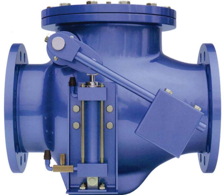
Operation of Internal Cushion
As illustrated below, the cushioning of a pneumatic/hydraulic cylinder stroke is obtained by trapping the
exhaust air/oil as the piston assembly nears the end of its stroke. In Figure 7, as the Cushion Plunger (1)
enters Cushion Cavity (2), the exhaust air/oil is almost completely trapped by the Ball Check (3) and the
Adjusting Screw (4) creating back-pressure against Piston Assembly. The back-pressure cushions and slows
the final part of the Piston stroke thus, reducing impact of the Piston Assembly against the Cylinder Cap.
Turning the Adjusting Screw to allow more or less air/oil to escape regulates the degree of cushioning as
desired.
In Figure 8, when air/oil enters the Cylinder Cap End to stroke the Piston Assembly in the opposite direction,
the air/oil moves the Ball Check (3) off its seat, opening the passage for more air/oil to act against the Piston,
thus speeding its start-up movement as the Cushion Plunger (1) is immediately forced out of its cavity (2).
Figure 7 – Cushion “IN” Stroke Figure 8 – Cushion “OUT” Stroke
January 2022 Page 20 D12006DeZURIK
APCO CVS-6000/6000A Swing Check Valves with Air Cushion Cylinder, Oil Controlled Cylinder and Oil
Controlled Bottom Mounted Buffer
Timing Valve Adjustment (CVS-6000-OC Valves)
The Timing Valve (B45) automatically starts the second stage of closure control. When the Cam (B47) is
depressed, the Disc (A10) can travel toward closed freely. Oil flows directly from the Cylinder (B20) to the Oil
Reservoir Tank (B40), bypassing the Flow Control Valve (B30). The unrestricted flow of oil allows rapid disc
travel toward closed. When the Cam is released, Disc speed of travel is controlled by the adjustable Flow
Control Valve. The travel distance before the second stage of closure control begins is set by adjusting the
Cam.
• Turning the Cam counter-clockwise will increase the Disc travel distance before the Roller releases
the Cam, permitting the Disc to close at a fast rate for longer travel distance.
• Turning the Cam clockwise will decrease the Disc travel distance before the Roller releases the Cam,
permitting the Disc to close at a fast rate for shorter travel distance.
• If the Cam is adjusted so the Cam and Roller do not make contact at all, the second stage Flow Control
Valve will control the Disc movement from full open to 90% closed. At 90% closed, the third stage of
control starts (See “Operation of Internal Cushion”)
Figure 9 shows position of the Cam in relation to Cam Follower with check valve in closed position. The cam is
connected to the valve Pivot Shaft and rotates in the same direction as the disc travels. In this example, the
Cam is set to allow the disc to rapidly close from full open to 50% open before second stage closure control
begins.
Figure 9 – Timing Valve
January 2022 Page 21 D12006DeZURIK
APCO CVS-6000/6000A Swing Check Valves with Air Cushion Cylinder, Oil Controlled Cylinder and Oil
Controlled Bottom Mounted Buffer
Oil Filling Procedure
See Figures 2 through 5 for part identification. Recommended Oils: Motor oil SAE 20, Mobil DTE 24, Castrol
Hyspin AW 32.
CVS-6000-OC Valves
1. Fully close swing check valve.
2. Fully open Flow Control Valve (B30). (Make note of setting before turning knob.)
3. Manually lift roller of Timing Valve (B45) and hold in that position until step 5.
4. Remove pipe plug in street elbow located on side of Oil Reservoir (B58) and slowly fill with oil until
oil level is visible in street elbow, then replace pipe plug.
5. Manually open and close swing check valve by lifting Counterweight Arm (B28) at least three times
to force out any entrapped air in the cylinder(s).
6. Remove pipe plug in street elbow located on side of Oil Reservoir Tank (B40) and check oil level.
Refill if necessary and repeat step 5 until proper oil level is maintained when the swing check valve
is fully closed.
7. Check system for any entrapped air by manually opening the swing check valve by lifting
Counterweight Arm (B28), then closing the Flow Control Valve (B30) while still on the open position.
The Disc (A10) should remain in the open position, otherwise, repeat steps 2 thru 7.
8. Reset Flow Control Valve (B30) to original setting noted in Step 2.
CVS-6000-BMB Valves
Step 1: Hydro Pneumatic Accumulator (B73)
1. Shut down pump.
2. Release pressure of Hydro Pneumatic Tank and remove pipe plug located on the side of the
tank and also either the Pressure Gauge (B74) or Air Valve.
3. Fully open Flow Control Valve (B30). (Make note of setting before turning knob.)
4. Slowly fill cylinder with oil until it spills out of the side port. This is the oil fill level.
5. Replace both fittings and pressurize tank according to this formula:
6. Tank pressure = (Line pressure/4) + 5 psi
7. Start pump and observe if Buffer Rod (B84) extends. If not, while valve is still open add more
pressure until it does.
8. Reset Flow Control Valve (B30) to original setting noted in step 3.
Step 2: Oil Reservoir (B58)
1. Start pump.
2. Fully open Flow Control Valve (B30). (Make note of setting before turning knob.)
3. Remove side Pipe Plug (B12) and Air Breather (B14) and slowly fill with oil until it spills out of
the side port.
4. Replace both fittings.
5. Shut down pump.
6. Reset Flow Control Valve (B30) to original setting noted in step 2.
NOTE: The Oil Reservoir should be under atmospheric condition at all times.
January 2022 Page 22 D12006DeZURIK
APCO CVS-6000/6000A Swing Check Valves with Air Cushion Cylinder, Oil Controlled Cylinder and Oil
Controlled Bottom Mounted Buffer
Troubleshooting
Condition Possible Cause Corrective Action
Shaft seal leaks. Seal is worn. Replace seal.
Foreign matter caught between Fully open valve to remove
Valve leaks excessively from disc and seat. object.
one side of the disc to the other.
Disc seat is worn or damaged. Replace disc seat.
Loose flange bolting. Tighten flange bolting.
Blown flange gasket. Replace flange gasket.
Miss-alignment or damage to Adjust miss-alignment or repair
Valve leaks at flange joint.
field piping and supports. piping or supports.
Repair flange, replace valve
Damaged flange face/s or
body or adjust flange
improper flange connections.
connections.
Object is wedged between seat Fully open valve to remove
Valve does not fully close.
and disc. object.
January 2022 Page 23 D12006Limited Warranty
DeZURIK, Inc. (“Seller”) manufactured products, auxiliaries and parts for a period of twenty-four (24) months from date of shipment from
Seller’s factory, are warranted to the original purchaser only against defective workmanship and material, but only if properly stored, installed,
operated, and serviced in accordance with Seller’s recommendations and instructions.
For items proven to be defective within the warranty period, your exclusive remedy under this limited warranty is repair or replacement of
the defective item, at Seller’s option, FCA Incoterms 2020 Seller’s facility with removal, transportation, and installation at your cost.
Products or parts manufactured by others but furnished by Seller are not covered by this limited warranty. Seller will provide repair or
replacement for other’s products or parts only to the extent provided in and honored by the original manufacturer’s warranty to Seller, in
each case subject to the limitations contained in the original manufacturer’s warranty.
No claim for transportation, labor, or special or consequential damages or any other loss, cost or damage is being provided in this limited
warranty. You shall be solely responsible for determining suitability for use and in no event shall Seller be liable in this respect.
This limited warranty does not warrant that any Seller product or part is resistant to corrosion, erosion, abrasion or other sources of failure,
nor does Seller warrant a minimum length of service.
Your failure to give written notice to us of any alleged defect under this warranty within twenty (20) days of its discovery, or attempts by
someone other than Seller or its authorized representatives to remedy the alleged defects therein, or failure to return product or parts for
repair or replacement as herein provided, or failure to store, install, or operate said products and parts according to the recommendations
and instructions furnished by Seller shall be a waiver by you of all rights under this limited warranty.
This limited warranty is voided by any misuse, modification, abuse or alteration of Seller’s product, accident, fire, flood or other Act of God,
or your failure to pay entire contract price when due.
The foregoing limited warranty shall be null and void if, after shipment from our factory, the item is modified in any way or a component of
another manufacturer, such as but not limited to, an actuator is attached to the item by anyone other than a Seller factory authorized service
personnel.
All orders accepted shall be deemed accepted subject to this limited warranty, which shall be exclusive of any other or previous Warranty,
and this shall be the only effective guarantee or warranty binding on Seller, despite anything to the contrary contained in the purchase order
or represented by any agent or employee of Seller in writing or otherwise, notwithstanding, including but not limited to implied warranties.
THE FOREGOING REPAIR AND REPLACEMENT LIMITED WARRANTY IS IN LIEU OF ALL OTHER WARRANTIES, OBLIGATIONS AND
LIABILITIES, INCLUDING ALL WARRANTIES OF FITNESS FOR A PARTICULAR PURPOSE OR OF MERCHANTABILITY OR
OTHERWISE, EXPRESSED OR IMPLIED IN FACT OR BY LAW, AND STATE SELLER’S ENTIRE AND EXCLUSIVE LIABILITY AND YOUR
EXCLUSIVE REMEDY FOR ANY CLAIM IN CONNECTION WITH THE SALE AND FURNISHING OF SERVICES, GOODS OR PARTS,
THEIR DESIGN, SUITABILITY FOR USE, INSTALLATION OR OPERATIONS.
Disclaimer
Metric fasteners should not be used with ASME Class 150/300 bolt holes and flange bolt patterns. If you use metric fasteners with ASME
Class 150/300 bolt holes and flange bolt patterns, it may lead to product failure, injury, and loss of life. DeZURIK Inc. disclaims all liability
associated with the use of metric fasteners with ASME Class 150/300 bolt holes and flange patterns, including but not limited to personal
injury, loss of life, loss of product, production time, equipment, property damage, lost profits, consequential damages of any kind and
environment damage and/or cleanup. Use of metric fasteners with ASME Class 150/300 bolt holes and flange bolt patterns is a misuse that
voids all warranties and contractual assurances. If you use metric fasteners with ASME Class 150/300 bolt holes and flange bolt patterns,
you do so at your sole risk and any liability associated with such use shall not be the responsibility of DeZURIK, Inc. In addition to the
foregoing, DeZURIK’s Manufacturer’s Conditions apply.
Limitation of Liability
IN NO EVENT SHALL SELLER BE LIABLE FOR ANY DIRECT, INDIRECT, SPECIAL, PUNITIVE, OR CONSEQUENTIAL DAMAGES
WHATSOEVER, AND SELLER’S LIABILITY, UNDER NO CIRCUMSTANCES, WILL EXCEED THE CONTRACT PRICE FOR THE GOODS
AND/OR SERVICES FOR WHICH LIABILITY IS CLAIMED. ANY ACTION FOR BREACH OF CONTRACT BY YOU, OTHER THAN RIGHTS
RESPECTING OUR LIMITED WARRANTY DESCRIBED ABOVE, MUST BE COMMENCED WITHIN 12 MONTHS AFTER THE DATE OF
SALE.
Sales and Service
For information about our worldwide locations, approvals, certifications and local representative:
Web site: www.dezurik.com E-Mail: info@dezurik.com
250 Riverside Ave. N., Sartell, MN 56377 ● Phone: 320-259-2000 ● Fax: 320-259-2227
DeZURIK, Inc. reserves the right to incorporate our latest design and material changes without notice or obligation.
Design features, materials of construction and dimensional data, as described in this manual, are provided for your information only
and should not be relied upon unless confirmed in writing by DeZURIK, Inc. Certified drawings are available upon request.
October 2021 Printed in U.S.A.You can also read