ALIS Airport Luggage Identification System - MMMI - SICK Germany
←
→
Page content transcription
If your browser does not render page correctly, please read the page content below
MMMSYSTEM
                                           S Y S T E M DESCRIPTION
                                                       D E S C R I P T I O NMMMI

ALIS
Airport Luggage Identification System

Track and Trace Systems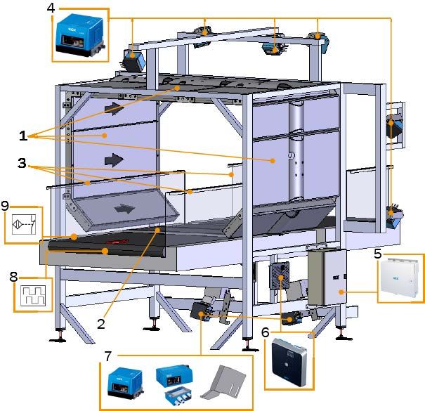
Described Product
                               ALIS
                               Airport Luggage Identification System

                               Manufacturer
                               SICK AG
                               Erwin-Sick-Str. 1
                               D-79183 Waldkirch
                               Germany

                               Production Location
                               SICK AG AG
                               Gisela-Sick-Str. 1
                               D-79276 Reute
                               Germany

                               Legal Information
                               This work is protected by copyright. Any rights derived from the copyright shall be reserved
                               for SICK AG. Reproduction of this document or parts of this document is only permissible
                               within the limits of the legal determination of Copyright Law. Any modification, reduction or
                               translation of this document is prohibited without the express written permission of SICK
                               AG.

                               The trademarks stated in this document are the property of their respective owner.

                               © SICK AG. All rights reserved

                               Original Document
                               This document is an original document of SICK AG.

2   S Y S T E M D E S C R I P T I O N | ALIS                                                            8027605/V1-0/2022-03| SICK
                                                                                                        Subject to change without notice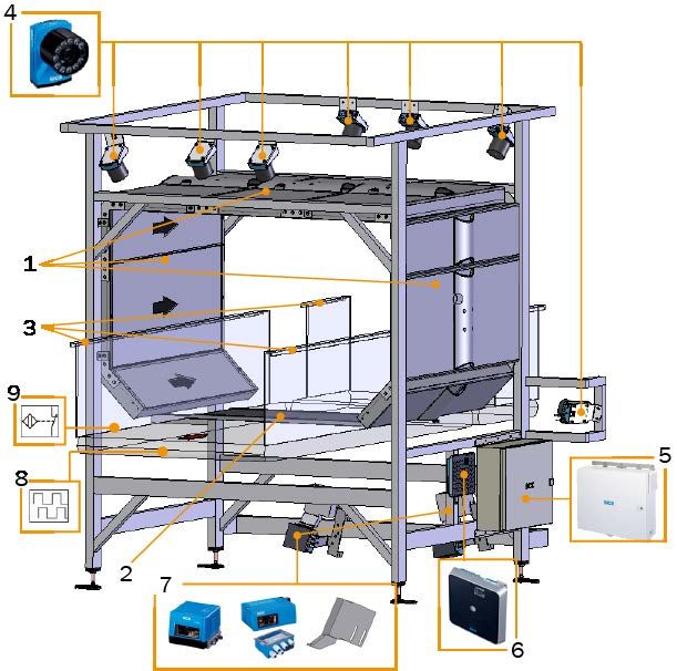
CONTENT

Content
                                   1   About this Document ................................................................................ 7
                                       1.2     Purpose of this Document .............................................................................. 7
                                       1.3     Target Group.................................................................................................... 7
                                       1.4     Further Information......................................................................................... 7
                                       1.5     Additional Technical Documentation/Information ........................................ 8
                                       1.6     Document Conventions................................................................................... 9

                                   2   Important Safety Instructions ................................................................11
                                       2.1     Intended Use .................................................................................................11
                                       2.2     Supplemental Directives...............................................................................11
                                       2.3     Requirements for the Qualification of Personnel ........................................11
                                       2.4     Potential Hazards..........................................................................................12
                                       2.5     Protective Devices.........................................................................................14
                                       2.6     System Warranty ...........................................................................................14
                                       2.7     RoHS-Directive ..............................................................................................14
                                       2.8     Safety Conventions .......................................................................................15
                                       2.9     Warning Signs on System Components .......................................................15
                                       2.10    Mandatory Signs ...........................................................................................16

                                   3   Systems Description................................................................................17
                                       3.1     ALIS Laser - Laser Based Bar Code Reading System ..................................18
                                       3.2     ALIS - Matrix Camera based Bar Code Reading System .............................19
                                               3.2.1     ALIS Camera - Camera System with 8 Matrix Cameras and 2 Laser
                                                         Scanners .......................................................................................19
                                               3.2.2     ALIS Camera - Camera System with 10 Matrix Cameras ............20
                                               3.2.3     ALIS Vision - Camera System with OCR&VC.................................20
                                       3.3     ALIS RFID - Radio Frequency Identification System ....................................21
                                       3.4     ALIS - Hybrid ..................................................................................................22
                                               3.4.1     RFID and Laser Scanner Reading System ...................................22
                                               3.4.2     RFID Camera and Laser Reading System....................................23
                                       3.5     General Information ......................................................................................24
                                               3.5.1     Integration Into Customer System ...............................................24
                                               3.5.2     Bar Code/RFID tag Specification .................................................25
                                               3.5.3     System Ambient Data ...................................................................25
                                               3.5.4     System Redundancy .....................................................................25

                                   4   System Components ...............................................................................27
                                       4.1     Laser Bar Code Scanner ...............................................................................27
                                               4.1.1    CLV691 Laser Bar Code Scanner ................................................27
                                               4.1.2    CLV691 Laser Bar Code Scanner with Mirror Hood ....................28
                                               4.1.3    CLV691 Laser Bar Code Scanner with Cleaning Unit..................29
                                               4.1.4    CLV651 Laser Bar Code Scanner (Option) ..................................30
                                       4.2     Image-Based Code Reader ...........................................................................31
                                               4.2.1    Lector654 Image-Based Code Reader ........................................31
                                               4.2.2    Lector654 Image-Based Code reader with Mirror.......................32

8027605/V1-0/2022-03| SICK                                                                                     S Y S T E M D E S C R I P T I O N | ALIS         3
Subject to change without notice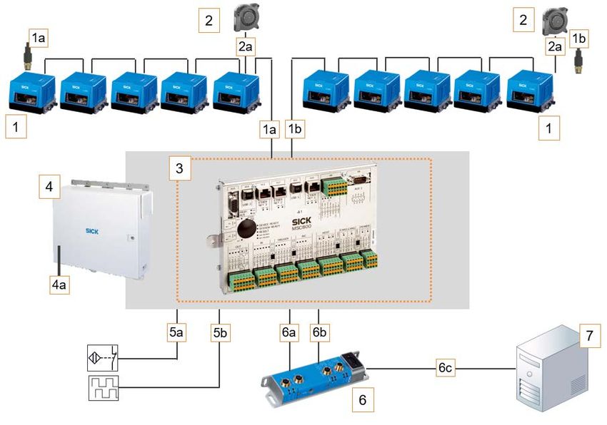
CONTENT

                                                     4.3     RFID............................................................................................................... 33
                                                             4.3.1       RFU630 - RFID Read Device ........................................................ 33
                                                             4.3.2       Modules with/without Antenna ................................................... 34
                                                     4.4     Cabinet incl. Controller ................................................................................. 35
                                                     4.5     Reflection Light Barrier - Trigger Signal ...................................................... 36
                                                     4.6     Incremental-Encoder DFV60 ........................................................................ 37
                                                     4.7     Accessories (option) ..................................................................................... 38
                                                             4.7.1       CDF600-2200 Field Bus Module (Option)................................... 38
                                                             4.7.2       Network Camera........................................................................... 39
                                                             4.7.3       Signal Lamp .................................................................................. 39

                                     5               Transport, Setup and Mounting............................................................. 41
                                                     5.1     Check Delivery .............................................................................................. 41
                                                     5.2     Transport and Setup..................................................................................... 41

                                     6               Electrical Installation............................................................................... 43
                                                     6.1     Connection Overview CLV691 - ALIS Laser ................................................. 44
                                                     6.2     Connection Overview Lector654 - ALIS Camera.......................................... 45
                                                     6.3     Connection Overview - ALIS RFID................................................................. 46

                                     7               Commissioning ........................................................................................ 47

                                     8               Operation .................................................................................................. 49
                                                     8.1     System Start ................................................................................................. 49
                                                     8.2     Check operational readiness ....................................................................... 49
                                                             8.2.1    CLV691 Bar Code Scanner .......................................................... 49
                                                             8.2.2    CLV651 Bar Code Scanner .......................................................... 49
                                                             8.2.3    Lector654 Code Reader............................................................... 50
                                                             8.2.4    RFU630......................................................................................... 50
                                                             8.2.5    MSC800 System Controller ......................................................... 50
                                                             8.2.6    System Readiness ........................................................................ 50
                                                             8.2.7    Automated Operating Mode......................................................... 51
                                                     8.3     System End ................................................................................................... 52
                                                             8.3.1    Stopping the Conveying Syste, .................................................... 52
                                                             8.3.2    Interrupting the Voltage Supply ................................................... 53

                                     9               Maintenance and Repair ........................................................................ 55
                                                     9.1     Regular Control Measurement ..................................................................... 56
                                                     9.2     Visual Control................................................................................................ 56
                                                     9.3     Cleaning Instructions.................................................................................... 56
                                                             9.3.1     Cleaning the CLV691/CLV651 .................................................... 56
                                                             9.3.2     Cleaning the Cleaning Unit for CLV691....................................... 57
                                                             9.3.3     Cleaning the Lector654 ............................................................... 58
                                                             9.3.4     Cleaning the Cabinet.................................................................... 59
                                                             9.3.5     Cleaning the Trigger ..................................................................... 59
                                                             9.3.6     Cleaning the Encoder ................................................................... 60

4         S Y S T E M D E S C R I P T I O N | ALIS                                                                                                  8027605/V1-0/2022-03| SICK
                                                                                                                                                    Subject to change without notice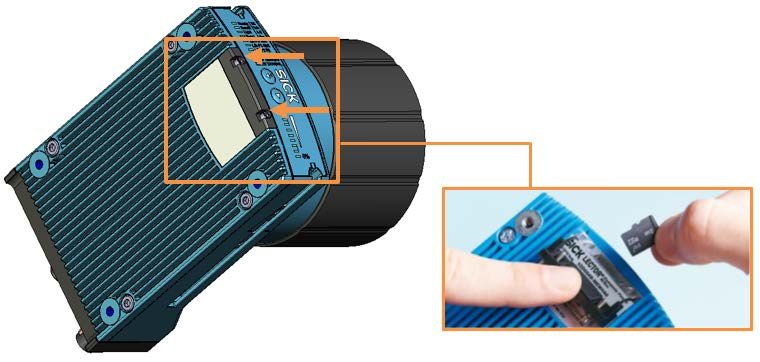
CONTENT

                                        9.4      Components Replacing .................................................................................61
                                                 9.4.1  CLV691 Replacing ........................................................................61
                                                 9.4.2  CLV651 Replacing ........................................................................63
                                                 9.4.3  Lector654 Replacing ....................................................................65
                                                 9.4.4  MSC800 System Controller Replacing.........................................67
                                                 9.4.5  MSC800 Battery Replacing ..........................................................68
                                                 9.4.6  Power Supply Unit Replacing........................................................69
                                                 9.4.7  Photoelectric Retro-Refelctive Sensor Replacing........................70
                                                 9.4.8  Incremental Encoder Replacing ...................................................71

                                   10   Fault Diagnosis.........................................................................................73
                                        10.1     Lector654 ......................................................................................................73
                                        10.2     CLV691 ..........................................................................................................73
                                        10.3     CLV651 ..........................................................................................................74
                                        10.4     MSC800 System Controller ..........................................................................74
                                                 10.4.1 MSC800 System Controller Check...............................................75
                                                 10.4.2 Detailed Fault Analysis .................................................................76

                                   11   Dimensional Drawings ............................................................................77
                                        11.1 ALIS Laser- Laser Based Bar Code Reading System ...................................77
                                        11.2 ALIS Camera - Camera Based Bar Code Reading System...........................79
                                             11.2.1 ALIS Camera - Camera System with 8 Matrix Cameras and 2 Laser
                                                       Scanner .........................................................................................79
                                             11.2.2 ALIS Camera - Camera System with 10 Matrix Cameras ............81
                                        11.3 ALIS RFID - Radio Frequency Identification System ....................................83
                                        11.4 ALIS - Hybrid ..................................................................................................85
                                             11.4.1 RFID and Laser Scanner Reading System ...................................85
                                             11.4.2 RFID Camera and Laser Scanner Reading System .....................87

                                   12   Disposal.....................................................................................................89

8027605/V1-0/2022-03| SICK                                                                                       S Y S T E M D E S C R I P T I O N | ALIS         5
Subject to change without notice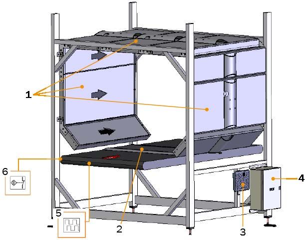
CONTENT

6         S Y S T E M D E S C R I P T I O N | ALIS   8027605/V1-0/2022-03| SICK
                                                     Subject to change without notice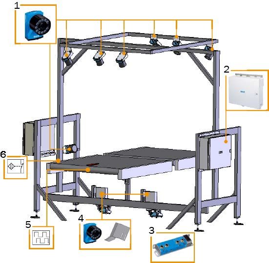
ABOUT THIS DOCUMENT 1

1                   About this Document
                                   Note
                                   This document regarding the ALIS - Airport Luggage Identification System:
                                   ●   contains information required during the life cycle of the system.
                                   ●   is available to all those people who work with the system.
                                   ●   read this document carefully and make sure that you understand the content fully
                                       before working with the system.

1.1                 Limitation of Liability

                                   Note
                                   All information and notes in this document have been compiled in accordance with the
                                   applicable standards and regulations, the state of the art and the manufacturer's many
                                   years of knowledge and experience.
                                   It is therefore pointed out that the manufacturer assumes no liability, particularly in the
                                   following cases:
                                   ●   Non-compliance with this document.
                                   ●   Failure to comply with instructions and regulations.
                                   ●   Unauthorized assembly and installation.
                                   ●   Unauthorized technical and other modifications.
                                   ●   Use of spare parts, wearing parts and accessories not approved by the manufacturer.
                                   ●   Unauthorized changes, adjustments and/or manipulations of software.
                                   ●   Non-performance of regular maintenance work and its documentation.
                                   The actual scope of delivery may deviate from the features and illustrations described
                                   here in the case of special designs, the use of additional ordering options or due to the
                                   latest technical changes.

1.2                 Purpose of this Document
                                   This document describes the ALIS - Airport Luggage Identification Systems.

1.3                 Target Group
                                   This document is intended for qualified personnel which are authorized to work on the ALIS.

1.4                 Further Information
                                   Special local conditions
                                   Follow all local laws, technical rules, and company-internal operating directives applicable
                                   at the respective installation site of the ALIS.

                                   Preserving the documents
                                   This document and the additional technical documentation and information must be:
                                   ●   Available for reference.
                                   ●   Passed on to new system operator or new employees.

8027605/V1-0/2022-03| SICK AG                                                                S Y S T E M D E S C R I P T I O N | ALIS   7
Subject to change without notice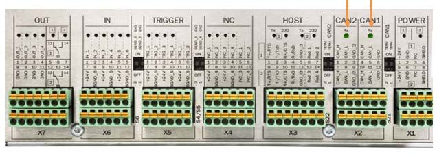
1 ABOUT THIS DOCUMENT

1.5       Additional Technical Documentation/Information
                                  ●    Technical System-Documentation:
                                       – Wiring diagram
                                       – Technical drawings
                                  ●    Original SICK operating instructions for optional products and components can be found
                                       at www.sick.com

                                    ID-Number       Components                                                  Manufacturer
                                    8016185         Lector64x/65x - Image-Based Code Readers                    SICK
                                    8014335         RFU63x - RFID read/write device (UHF)                       SICK
                                    8014396         CLV69x - Bar Code Scanners                                  SICK
                                    8019588         CLV65x - Bar Code Scanners                                  SICK
                                    8015922         CDF600-2200 - PROFINET IO (Option)                          SICK
                                    8013709         DFV60 - Incremental Encoder                                 SICK
                                    8011540         MSC800 - Modular System Controller                          SICK

8      S Y S T E M D E S C R I P T I O N | ALIS                                                           8027605/V1-0/2022-03| SICK
                                                                                                          Subject to change without notice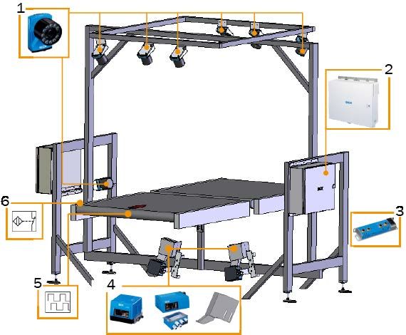
ABOUT THIS DOCUMENT 1
1.6 Document Conventions
Required tools
▸ Instruction
Instruction result
Refer to another document.
All units of measurement in this document are originally metric units.
Subject to change without notice.
Images might differ from actual design.
8027605/V1-0/2022-03| SICK AG S Y S T E M D E S C R I P T I O N | ALIS 9
Subject to change without notice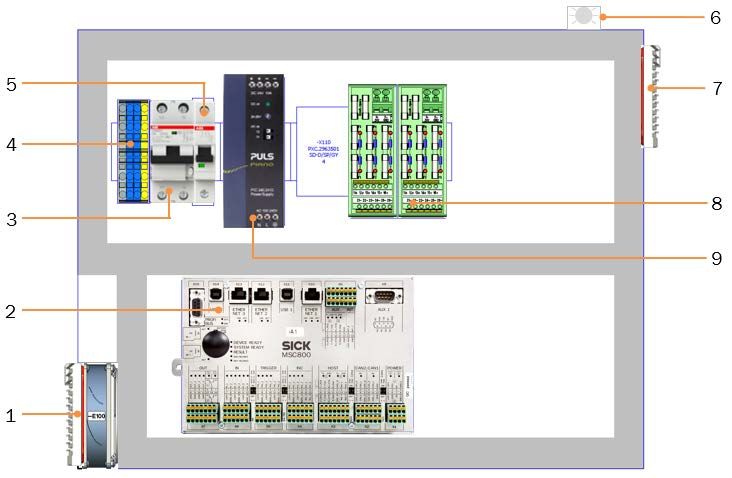
1 ABOUT THIS DOCUMENT

10     S Y S T E M D E S C R I P T I O N | ALIS   8027605/V1-0/2022-03| SICK
                                                  Subject to change without notice
IMPORTANT SAFETY INSTRUCTIONS 2
2 Important Safety Instructions
2.1 Intended Use
With the ALIS (Airport Luggage Identification System) track and trace system, luggage can
be clearly identified as it is transported quickly and reliably through the airport and thus
reaches the right sorting zone.
Designed like a reading interval gate, SICK has developed ALIS specifically with luggage
handling services in mind.
The system is extremely reliable when it comes to reading luggage information on IATA bar
codes and/or RFID tagged labels.
With ALIS, SICK has created a modular system which can be specially adapted to suit the
various requirements of airport luggage identification and handling processes, whether this
involves sensors, visualization software, or even the commissioning process.
Intended use also includes compliance with this system information, especially the sources
of danger.
2.2 Supplemental Directives
▸ Before working on the ALIS, read this document carefully and follow all safety instruc-
tions and information.
▸ Only qualified persons from the respective areas are permitted to work on the ALIS.
▸ Follow operating procedures.
▸ Follow local regulations.
▸ Observe local regulations for working with gas and electrical components.
▸ Access to the ALIS is restricted to authorized personnel only.
System damage/transport damage
▸ Damage to individual components can lead to malfunctions of the entire system.
▸ Do not ignore system components damaged during transport.
▸ In the event of damage, contact SICK Service.
2.3 Requirements for the Qualification of Personnel
Only qualified personnel from the respective field are permitted to work on the system.
● Qualified personnel have the specialist training, skills, and experience, as well as know-
ledge of the relevant regulations and standards, to be able to perform tasks delegated to
them and to detect and to avoid any potential dangers independently.
● Electricians have the specialist training, skills, and experience, as well as knowledge of
the relevant standards and provisions to be able to carry out work on electrical systems
and to detect and avoid any potential dangers independently.
8027605/V1-0/2022-03| SICK S Y S T E M D E S C R I P T I O N | ALIS 11
Subject to change without notice2 IMPORTANT SAFETY INSTRUCTIONS
2.4 Potential Hazards
Optical radiation Laser class 1
The Lector65x camera-based code readers have a targeting laser as a setup aid.
The accessible radiation does not pose a hazard even when viewed directly for long periods
of time, (time base 100 seconds). In the case of visible lasers (red), temporary irritating
optical effects on the human eye (e.g. glare, flash blindness, afterimages, impairment of
color vision) cannot be completely ruled out, especially at low ambient brightness.
▸ Do not look into the switched-on light source.
▸ Do not look directly at the laser with optical instruments (magnifying glasses, micro-
scopes).
▸ Observe current national regulations on laser protection.
Optical radiation Laser class 2
The human eye is not at risk when briefly exposed to the radiation for up to 0.25 seconds.
Exposure to the laser beam for longer periods of time may cause damage to the retina.
The laser radiation is harmless to human skin.
▸ Do not look into the laser beam intentionally.
▸ Never point the laser beam at people's eyes.
▸ If it is not possible to avoid looking directly into the laser beam, e.g., during commission-
ing and maintenance work, suitable eye protection must be worn.
▸ Avoid laser beam reflections caused by reflective surfaces. Be particularly careful during
mounting and alignment work.
▸ Do not open the housing. Opening the housing may increase the level of risk.
▸ Current national regulations regarding laser protection must be observed.
Optical radiation LED light (RG2)
Camera system and the integrated LED illumination of the Lector65x use LEDs of the RG2
risk group.
The optical radiation can cause serious eye injuries if the following points are not observed:
▸ Do not look into the light source for extended periods of time.
▸ Do not point the light source at people and prevent reflections of the light source from
reflective surfaces onto people.
▸ During commissioning or maintenance work, suitable eye protection must be worn.
▸ Do not open the housing.
▸ Comply with the recent national version of the applicable standards on photobiological
safety of lamps and lamp systems.
Electric voltage
Touching live devices, which may still be energized, can lead to death, burns or electrical
shock.
▸ Electrical work may only be performed on the system by qualified specialist personnel.
▸ Before working on electrical components, observe the five safety rules:
▸ Disconnect.
▸ Secure against being switched back on.
▸ Ensure that there is no voltage.
▸ Ground and short-circuit.
▸ Cover or enclose live parts in the vicinity.
12 S Y S T E M D E S C R I P T I O N | ALIS 8027605/V1-0/2022-03| SICK
Subject to change without noticeIMPORTANT SAFETY INSTRUCTIONS 2
Hot surfaces
Components can be hot. Contact may cause burn and serious injuries.
▸ Do not touch hot surfaces.
▸ Use appropriate safety gloves.
Suspended loads
▸ Never enter the area under suspended loads.
▸ Pay close attention when lifting loads.
▸ Comply with lifting instructions to prevent injuries and accidents.
▸ Use suitable, undamaged lifting tools.
▸ Wear personal protective equipment (safety helmet, safety shoes).
8027605/V1-0/2022-03| SICK S Y S T E M D E S C R I P T I O N | ALIS 13
Subject to change without notice2 IMPORTANT SAFETY INSTRUCTIONS
2.5 Protective Devices
The ALIS systems are designed in a way that allows for safe operation. Protective devices
reduce potential risks to the maximum possible extent.
Side panels prevent the bags from falling.
2.6 System Warranty
Any warranty claim expires if:
▸ Safety instructions and measures in this document are not observed.
▸ Parts or components of the Continuous Emission Monitoring System are installed,
assembled or modified without authorization.
▸ The ALIS is changed or modified.
▸ Software is changed, adapted and/or manipulated without authorization.
2.7 RoHS-Directive
This product is designed for applications in large industrial plants according to
Article 2 (4) e, RoHS 2011/65/EU and can therefore only be used in such systems.
The product is neither suitable nor approved for use outside of these systems.
SICK cannot assume any kind of warranty or liability for use outside of these systems..
14 S Y S T E M D E S C R I P T I O N | ALIS 8027605/V1-0/2022-03| SICK
Subject to change without noticeIMPORTANT SAFETY INSTRUCTIONS 2
2.8 Safety Conventions
The warnings used in this manual have the following meanings:
DANGER
Indicates a hazardous situation which, if not avoided, will result in death or serious
injury.
WARNING
Indicates a hazardous situation which, if not avoided, could result in death or serious
injury.
CAUTION
indicates a hazardous situation which, if not avoided, could result in minor or moder-
ate injuries.
NOTICE
Indicates a situation which that can lead to material damage if not avoided.
2.9 Warning Signs on System Components
Do not remove or cover warning stickers. Damaged or missing stickers must be replaced.
Sign Significance
Warning of a danger point
Warning of dangerous electrical voltage
Warning of laser light / LED light
Warning of hot surfaces
Warning of suspended loads
8027605/V1-0/2022-03| SICK S Y S T E M D E S C R I P T I O N | ALIS 15
Subject to change without notice2 IMPORTANT SAFETY INSTRUCTIONS
2.10 Mandatory Signs
Mandatory signs indicate a measure that is required to protect personal health and / or
avoid the risk of personal injury.
Mandatory signs on the system must not be removed or covered. Damaged or missing
mandatory signs (stickers) must be replaced.
Sign Significance
Read instructions manual
Wear safety gloves
Wear eye protection
Wear hard hat
Wear safety boots
Disconnect before maintenance or repair
16 S Y S T E M D E S C R I P T I O N | ALIS 8027605/V1-0/2022-03| SICK
Subject to change without noticeSYSTEMS DESCRIPTION 3
3 Systems Description
The ALIS is a fully automatic reading gate including frame, scan heads with on-board
decoder, local network controller and host communication for reading bar codes on flight
baggage, which in turn is located e.g. on conveyor belts, cross belts or tilt tray sorter sys-
tems.
The local network-controller incorporates a controller for the local scanner-network, opto-
isolated digital diagnostic software, flexible HOST-Interface and an interface supplying diag-
nostic data to the Diagnostic Tool “Baggage Analytics” or "Logistics Diagnostic Analytics".
More information about the diagnostic software can be found on SICK.com.
The HOST-interface can be adapted to customers specific requirements in terms of HOST-
Protocol and physical interface.
The complete system consists of a certain amount of bar code readers or/and RFID reader
and antennas - depending on the application -, the control unit MSC800 unit, photoelectric
switches for object-trigger, cables and an increment encoder for measuring the conveyor
speed.
System Types
● ALIS Laser - Laser based bar code reading
● ALIS Cam - Matrix cameras based bar code reading, two versions:
– with 10 matrix cameras, 2 of them for bottom reading
– with 8 matrix cameras and 2 laser scanners for bottom reading
● ALIS RFID - Reading and assignment of RFID tags
● ALIS Hybrid - combination of RFID and further identification readers, two versions:
– with RFID and laser scanners
– with RFID and matrix cameras
8027605/V1-0/2022-03| SICK S Y S T E M D E S C R I P T I O N | ALIS 17
Subject to change without notice3 SYSTEMS DESCRIPTION
3.1 ALIS Laser - Laser Based Bar Code Reading System
Fig. 1: Components of the 6 side ALIS reading gate based on laser scanners
Legend
1 Eight CLV691 fixed mount bar code scanner
2 Cabinet with controller and power supply unit
3 Field bus module for PROFINET (optionally)
4 Two CLV691 fixed mount bar code scanner with cleaning unit
optionally 3 - 4 CLV651 fixed mount bar code scanners with
cleaning unit and connection unit
5 Incremental signal
6 Trigger signal
18 S Y S T E M D E S C R I P T I O N | ALIS 8027605/V1-0/2022-03| SICK
Subject to change without noticeSYSTEMS DESCRIPTION 3
3.2 ALIS - Matrix Camera based Bar Code Reading System
3.2.1 ALIS Camera - Camera System with 8 Matrix Cameras and 2 Laser Scanners
Fig. 2: Components of the 6 side ALIS reading gate based on Lectors654 and 2 CLV691
Legend
1 Eight Lector654 image based code reader
2 Cabinet with controller, power supply and Ethernet switch
3 Field bus module for PROFINET (optionally)
4 Two CLV691 fixed mount bar code scanner with cleaning unit
optionally 3 - 4 CLV651 fixed mount bar code scanners with
cleaning unit and connection unit
5 Incremental signal
6 Trigger signal
8027605/V1-0/2022-03| SICK S Y S T E M D E S C R I P T I O N | ALIS 19
Subject to change without notice3 SYSTEMS DESCRIPTION
3.2.2 ALIS Camera - Camera System with 10 Matrix Cameras
Fig. 3: Components of the 6 side ALIS reading gate based on Lector654
Legend
1 Eight Lector654 image based code reader
2 Cabinet with controller, power supply and Ethernet switch
3 Field bus module for PROFINET (optionally)
4 Two Lector654 with cleaning unit
5 Incremental signal
6 Trigger signal
3.2.3 ALIS Vision - Camera System with OCR&VC
The ALIS camera can be supplemented with optical character recognition and/or video
coding.
This makes up the ALIS Vision. In the event that the baggage source message is missing,
the data (flight number, destination code, license plate number) that is relevant to sorting
can be read on the baggage tag in conjunction with OCR or VC. Less manual reprocessing
of the baggage item is required.
The number of bags going to the manual encoding station is further reduced. This results in
a higher sorting rate and optimizes the process time of transfer bags.
20 S Y S T E M D E S C R I P T I O N | ALIS 8027605/V1-0/2022-03| SICK
Subject to change without noticeSYSTEMS DESCRIPTION 3
3.3 ALIS RFID - Radio Frequency Identification System
Fig. 4: Components of the ALIS RFID
Legend
1 Absorber modules with integrated antenna.
The remaining modules are without antennas
2 Bottom antenna mounted between conveyor bed and conveyor belt
3 RFU630 read/write device
4 Cabinet with controller and power supply unit
5 Incremental signal
6 Trigger signal
8027605/V1-0/2022-03| SICK S Y S T E M D E S C R I P T I O N | ALIS 21
Subject to change without notice3 SYSTEMS DESCRIPTION
3.4 ALIS - Hybrid
3.4.1 RFID and Laser Scanner Reading System
Fig. 5: Components of the ALIS RFID - Laser combination
Legend
1 Absorber modules with integrated antenna.
The remaining modules are without antennas.
2 Bottom antenna mounted between conveyor bed and conveyor belt
3 Side guards must not be made of metal
(not included in SICK scope of delivery)
4 Eight CLV691 fixed mount bar code scanner
5 Cabinet with controller and power supply unit
6 RFU630 read/write device
7 Two CLV691 fixed mount bar code scanner with cleaning unit
8 Incremental signal
9 Trigger signal
22 S Y S T E M D E S C R I P T I O N | ALIS 8027605/V1-0/2022-03| SICK
Subject to change without noticeSYSTEMS DESCRIPTION 3
3.4.2 RFID Camera and Laser Reading System
Fig. 6: Components of the ALIS RFID, camera and Laser combination
Legend
1 Absorber modules with integrated antenna.
The remaining modules are without antennas.
2 Bottom antenna mounted between conveyor bed and conveyor belt
3 Side guards must not be made of metal
(not included in SICK scope of delivery)
4 Eight Lector654 image based code reader
5 Cabinet with controller and power supply unit
6 RFU630 read/write device
7 Two CLV691 fixed mount bar code scanner with cleaning unit
8 Incremental signal
9 Trigger signal
8027605/V1-0/2022-03| SICK S Y S T E M D E S C R I P T I O N | ALIS 23
Subject to change without notice3 SYSTEMS DESCRIPTION
3.5 General Information
3.5.1 Integration Into Customer System
Fig. 7: Integration in customer system
Legend
1 Track and trace system (example)
2 Conveyor technology provided by customer
3 Inbound conveyor
4 Outbound conveyor
Conveyor Systems
A conveyor system provided by the system integrator conveys the objects to the reading sta-
tion of the track and trace system.
The bar code reading can be realized by top, front, rear, side and underbelt mounted scan-
ners or cameras.
For underbelt reading the recommended belt gap is:
– with laser scanners of 50mm
– with cameras of 80mm
Note
For standard systems, the conveyor must be straight. However, it is also possible to install
systems in curves, but these are then customized.
24 S Y S T E M D E S C R I P T I O N | ALIS 8027605/V1-0/2022-03| SICK
Subject to change without noticeSYSTEMS DESCRIPTION 3
3.5.2 Bar Code/RFID tag Specification
Bar Code
● Bar code must be according to IATA Resolution 740, Attachment ‘B’ / chapter 2.
Large Sortation Bar Code Specification
● Symbology: interleaved 2 of 5
● Module width: 0,508mm / Tolerance: +/- 5%
● Bar height: min. 48mm
● Quiet zone: min. 7 times module width / preferred: 10 times module width
● Orientation: horizontal, vertical or orthogonal. Preferred: orthogonal
● Print contrast signal: not less then 80% at wavelength of 633nm
RFID tag
● The RFID tag must be compliant with the requirements of IATA RP 1740C
3.5.3 System Ambient Data
● Ambient operating temperature from 0° to 40°C / upon request 50° C possible
● Permissible relative humidity max. 90%, non-condensing
● Ambient light immunity 2000 lx on bar code
3.5.4 System Redundancy
In a redundant system two controllers MSC800 are running simultaneously. One MSC is
parameterized as "Primary controller" and the other one as "Secondary controller".
This assignment is static and will never change during operation. The controller can be in
the operation mode ACTIVE or STANDBY. In normal operation mode the primary controller is
in ACTIVE mode and the secondary controller is in STANDBY mode.
The assignment of the reading results to the object is done by the controller which receives
the data of the connected sensors. The reading data is then transferred inside a XML for-
mat to the remote controller via CAN2 connection.
This mirroring of the data is done from the ACTIVE to the STANDBY controller and vice versa.
To ensure that both controllers will output the identical reading data, all relevant settings
have to be identical. Redundant operation is only possible in tracking mode of the system.
The primary controller checks periodically the system state and compares it with the sec-
ondary system state. If the readiness of the primary controller is less than the secondary,
the primary controller will change to mode STANDBY and the secondary controller will
change to mode ACTIVE.
8027605/V1-0/2022-03| SICK S Y S T E M D E S C R I P T I O N | ALIS 25
Subject to change without notice3 SYSTEMS DESCRIPTION
26 S Y S T E M D E S C R I P T I O N | ALIS 8027605/V1-0/2022-03| SICK
Subject to change without noticeSYSTEM COMPONENTS 4
4 System Components
4.1 Laser Bar Code Scanner
4.1.1 CLV691 Laser Bar Code Scanner
Fig. 8: CLV691 laser bar code scanner
Legend
1 Viewing window
2 Mounting points
3 Connector for parameter storage
Features
● Optical sensor for scanning bar codes
● Comprises a laser diode with optics, as well as an electronics unit with integrated
decoder. Both components are installed in a housing
● Light is emitted and received through the viewing window in the housing
Fig. 9: CLV691 aperture angle
Function
● Automated and non-contact detection and decoding of bar codes on a conveying line
after triggering
● A scan line is generated on the object in order to detect the bar code
● Auto focusing when the light beam hits the object
● The line pattern reflected from the bar code is recorded, processed, and decoded by the
CLV691
● The read result is transmitted to the MSC800 system controller
8027605/V1-0/2022-03| SICK S Y S T E M D E S C R I P T I O N | ALIS 27
Subject to change without notice4 SYSTEM COMPONENTS
4.1.2 CLV691 Laser Bar Code Scanner with Mirror Hood
If the CLV691 bar code scanner cannot be installed at the prescribed minimum distance to
the conveyor, the bar code reading can be done via a mirror. The mirrors can be installed on
either one or both sides of the system, depending on where the space restriction occurs.
Fig. 10: Bar code scanner CLV691 with mirror hoods
Legend
1 Bar code scanner placed on the mirror cover
2 Light beam exit through the glass front panel
Function
● Reduced reading distance by extending the light path and thus greater reading field
height through the use of mirror hoods.
● Adjustable exit angle of the laser beam via the deflection mirror.
For further information about the CLV691, refer to the respective SICK operating instruc-
tions.
28 S Y S T E M D E S C R I P T I O N | ALIS 8027605/V1-0/2022-03| SICK
Subject to change without noticeSYSTEM COMPONENTS 4
4.1.3 CLV691 Laser Bar Code Scanner with Cleaning Unit
Fig. 11: CLV691 with cleaning unit
Legend
1 CLV691 / CLV651 bar code scanner
2 Blow out nozzle
3 Fan housing with radial fan
Function
● The fixed mount bar code scanners mounted underneath the conveying equipment fea-
ture an integrated cleaning unit
● This prevents an increased risk of contamination of the viewing window underneath
the belt
● The bar code is read through a belt gap. Recommended gap: 50mm
● The air is blown over the viewing window of the fixed mount bar code scanner
● This blows off any dirt particles on the viewing window
For further information about the CLV691, refer to the respective SICK operating instruc-
tions.
8027605/V1-0/2022-03| SICK S Y S T E M D E S C R I P T I O N | ALIS 29
Subject to change without notice4 SYSTEM COMPONENTS
4.1.4 CLV651 Laser Bar Code Scanner (Option)
Fig. 12: CLV651 with cleaning unit and connection unit
Legend
1 Viewing window
2 Swivel connection
3 Cleaning unit
4 Cable glands
5 Connection type
6 Connection card inside the housing with LEDs, terminal strip and switches
Function
● CLV651 are used when there is not enough space under the belt. Distance floor to top of
belt < 750mm
● The CLV651 operates in the same way as the CLV691 fixed mount bar code scanner
● The bar code is read through a gap in the belt. Recommended gap: 50mm
● Each fixed mount bar code scanner features a cleaning unit
Connection unit
● The individual readers are connected via a CDB620 connection unit
● This allows for central voltage supply of the fixed mount bar code scanners and connec-
tion to one another via CAN bus
For further information about the CLV651, refer to the respective SICK operating instruc-
tions.
30 S Y S T E M D E S C R I P T I O N | ALIS 8027605/V1-0/2022-03| SICK
Subject to change without noticeSYSTEM COMPONENTS 4
4.2 Image-Based Code Reader
4.2.1 Lector654 Image-Based Code Reader
Fig. 13: Lector 654 image based code reader
Legend
1 Lector654 code reader
2 Lens
3 Protective cover for optics
4 Integrated LED illumination ring
5 Aiming laser
Features
● Optical sensor with integrated LED illumination unit and dynamic focus control for bar
code detection
● It allows the omni directional reading of bar codes on one side of an object, even with
varying object heights and code positions
Function
● Does not scan the code area; instead, takes several photos from the bar codes
● The read process is activated by a trigger signal provided by SICK or customer
● For the image recordings, the reading field is lit up with a powerful LED illumination unit
● The read result is transmitted to the MSC800 system controller
Fig. 14: Operating principle
8027605/V1-0/2022-03| SICK S Y S T E M D E S C R I P T I O N | ALIS 31
Subject to change without notice4 SYSTEM COMPONENTS
4.2.2 Lector654 Image-Based Code reader with Mirror
If the Lector654 Image based bar code reader cannot be installed at the prescribed mini-
mum distance to the conveyor, the reading can be done by using a mirror.
The mirrors can be installed on either one or both sides and even on top of the system,
depending on where the space restriction occurs.
Fig. 15: Lector654 with deflection mirror
Legend
1 Deflection mirror
2 Lector654
Function
● The resulting extension of the light path allows space-saving mounting of the sensors on
the conveyor system
● The deflection via the mirror is loss-free due to its special surface vaporization, as this
eliminates light refraction
● Figure 15 shows the arrangement of the side camera with mirror
For further information about the Lector654, refer to the respective SICK operating
instructions.
32 S Y S T E M D E S C R I P T I O N | ALIS 8027605/V1-0/2022-03| SICK
Subject to change without noticeSYSTEM COMPONENTS 4
4.3 RFID
4.3.1 RFU630 - RFID Read Device
The RFU630 read/write devices are intelligent 4Dpro sensors from the SICK RFU6xx (UHF)
product family. Version (working range): Long Range.
Thanks to their intelligent process logic, the devices can be used either as a standalone
solution or as part of a group in a CAN network. In read mode, the devices transmit the
results via a host interface to a higher-level computer (e.g. PLC) for further centralized pro-
cessing.
RFU630
● Using up to four external antennas, it processes all common transponders in the fre-
quency range of 860 - 960 MHz
● Before a UHF RFID device can be introduced and operated in a particular country or
region, radio approvals from the local authorities are required. In most cases, SICK has
already received approval. However, this must be checked in advance
For further information about the RFU630, refer to the respective SICK operating instruc-
tions.
8027605/V1-0/2022-03| SICK S Y S T E M D E S C R I P T I O N | ALIS 33
Subject to change without notice4 SYSTEM COMPONENTS
4.3.2 Modules with/without Antenna
The RFID system consists of modules that can be freely combined, enabling the tunnel
design to be adapted to the relevant on-site conditions quickly and conveniently.
As a result, the RFID system can respond flexibly to the different widths and heights of con-
veying systems, as well as to the different positions of tags on the objects passing through
it.
For the supporting of the modules a supporting frame is in scope of supply by SICK.
Reader modules
Reader modules feature an integrated antenna and integrated absorber panels.
These are covered on the inside by a plastic panel.
Abb. 16: Reader modules
Legend
1 Module with integrated antenna
2 Integrated absorber panel
3 Antenna downlead
4 Cutouts for antenna mounting
5 Cable channel
34 S Y S T E M D E S C R I P T I O N | ALIS 8027605/V1-0/2022-03| SICK
Subject to change without noticeSYSTEM COMPONENTS 4
4.4 Cabinet incl. Controller
Fig. 17: Cabinet with system controller MSC800
Legend
1 Air inlet cooling (with filter mat and cooler)
– Used only in ALIS camera systems
– ALIS Laser and RFID systems are equipped with a smaller cabinet without
air inlet cooling
2 MSC800 system controller
3 FI/LS switch (RCBO)
4 Terminals for voltage supply IN (100-264 V AC/ 50-60 Hz)
5 Power supply circuit breaker
6 White status LED
7 Air outlet for cooling (with filter mat)
8 Terminals (24 V DC) and fuse module OUT
9 Power supply unit for supplying voltage to the system components
– 10A power supply for a ALIS Laser or RFID system
– 20A power supply for a ALIS camera System
Function
● The power supply unit supplies the voltage to the sensors in the track and trace system
● Contains the MSC800 system controller, the central control unit of the track and trace
system
● The MSC800 system controller coordinates all connected sensors, and assigns the
received read results to the respective bags
● The read results are output to the higher-level customer system in a host telegram with a
defined format
● The track and trace system is connected to the customer’s PROFINET IO network via the
CDF600 fieldbus module (option) (see below)
NOTE
A white status LED lights up as soon as voltage is applied to the cabinet.
8027605/V1-0/2022-03| SICK S Y S T E M D E S C R I P T I O N | ALIS 35
Subject to change without notice4 SYSTEM COMPONENTS
4.5 Reflection Light Barrier - Trigger Signal
Fig. 18: Reflection light barrier
Legend
1 Reflection light barrier
2 Reflector
Function
● Used for optical contact less detection of objects
● A reflector is required for the function
● The emitted light signal is reflected back via a reflector
● The emitter and receiver are arranged in parallel in the housing of the retro-reflective
light barrier
● If the light beam is interrupted by an object, a switching signal is output to the MSC800
system controller
Trigger signal
● The track and trace system requires a trigger signal
● The trigger signal is supplied either SICK or by customer
● It is processed by the MSC800 system controller
● The trigger signal activates the connected readers and opens the reading gate
36 S Y S T E M D E S C R I P T I O N | ALIS 8027605/V1-0/2022-03| SICK
Subject to change without noticeSYSTEM COMPONENTS 4
4.6 Incremental-Encoder DFV60
Fig. 19: Incremental encoder DFV60
Legend
1 Wheel
2 Spring load mounting arm
Function
● Measuring wheel system, mounted under the conveyor belt.
● Large spring travel and steer ability of the spring arm to compensate for unevenness of
the measuring surface
Incremental signal
● The track and trace system requires an incremental signal
● The incremental signal is supplied either by SICK or by customer
● It is processed by the MSC800 system controller
● The belt speed is determined by means of the incremental signal
● The incremental signal together with the trigger signal enables definition of the
position of the object within the reading field
8027605/V1-0/2022-03| SICK S Y S T E M D E S C R I P T I O N | ALIS 37
Subject to change without notice4 SYSTEM COMPONENTS
4.7 Accessories (option)
4.7.1 CDF600-2200 Field Bus Module (Option)
Fig. 20: CDF600-2200 field bus module
Legend
1 Connection to the customer network
2 Serial data interface to the MSC800 controller
3 Connecting the voltage supply
4 Rotary encoding switch behind the side cover
Function
● Field bus proxy/gateway for connecting the track and trace system to a PROFINET IO net-
work
● Connected to the MSC800 data interface and the customer network
● Encoding switches that are mounted and protected behind the side cover and easily
accessible from the outside for easy setup of bus address and operating mode
For further information about the CDF600-2200 - Field Bus Module, refer to the respec-
tive SICK operating instructions.
38 S Y S T E M D E S C R I P T I O N | ALIS 8027605/V1-0/2022-03| SICK
Subject to change without noticeSYSTEM COMPONENTS 4
4.7.2 Network Camera
Fig. 21: Network camera from Axis P13 series
Characteristics
● Great image quality with a high level of details
● The P-Iris gives an optimal image clarity in complex lightning
● Flexibility to change lenses
● Additional illumination can be provided upon request
● Up to 5MP resolution
4.7.3 Signal Lamp
Fig. 22: Signal lamp
Signal color Significance
Green (flashing) Power supply on. Components ready for operation
Green (permanent) System started conveyor belt is running
Yellow (permanent) Maintenance mode active
Red (flashing) System in error mode
Red (permanent) System stopped via emergency stop button
8027605/V1-0/2022-03| SICK S Y S T E M D E S C R I P T I O N | ALIS 39
Subject to change without notice4 SYSTEM COMPONENTS
40 S Y S T E M D E S C R I P T I O N | ALIS 8027605/V1-0/2022-03| SICK
Subject to change without noticeTRANSPORT, SETUP AND MOUNTING 5
5 Transport, Setup and Mounting
All transport, assembly, mounting, and electrical installation work must only be carried out
by qualified persons.
● Qualified persons have the specialist training, skills, experience and knowledge of the
relevant regulations and standards needed to be able to perform work assigned to them
and to identify and avoid any potential dangers independently
● Electricians have the professional training, skills, experience and knowledge of the rele-
vant standards and provisions needed to work on electrical systems and to detect and
avoid any potential dangers independently
NOTE
Assembly, mounting, and electrical installation work is carried out by SICK Service.
5.1 Check Delivery
▸ Completeness
▸ Transport damage
5.2 Transport and Setup
The components of the track and trace system are delivered on transport pallets.
▸ Transport the transport pallets to the operation site.
▸ Use suitable transportation equipment (manned forklift truck). Observe the center of
gravity.
▸ The installation side must be clean, level and free from obstacles.
8027605/V1-0/2022-03| SICK S Y S T E M D E S C R I P T I O N | ALIS 41
Subject to change without notice5 TRANSPORT, SETUP AND MOUNTING
42 S Y S T E M D E S C R I P T I O N | ALIS 8027605/V1-0/2022-03| SICK
Subject to change without noticeELECTRICAL INSTALLATION 6
6 Electrical Installation
All electrical work may only be performed by qualified persons.
● Qualified persons have the specialist training, skills, experience and knowledge of
the relevant regulations and standards needed to be able to perform work assigned
to them and to identify and avoid any potential dangers independently
● Electricians have the professional training, skills, experience and knowledge of the rele-
vant standards and provisions needed to work on electrical systems and to detect and
avoid any potential dangers independently
DANGER
HAZARDOUS ELECTRICAL VOLTAGE
Touching live devices, which may still be energized, can lead to death, burns or electri-
cal shock.
▸ Electrical work may only be performed on the system by qualified specialist person-
nel.
▸ Before working on electrical components, observe the five safety rules:
▸ Disconnect.
▸ Secure against being switched back on.
▸ Ensure that there is no voltage.
▸ Ground and short-circuit.
▸ Cover or enclose live parts in the vicinity
WARNING
DEVICE DAMAGE IF CONNECTED INCORECTLY
Any incorrect supply voltage may result in damage to the device.
▸ Only operate the cabinet with the specified supply voltage.
▸ All connected circuits must be designed as SELV circuits (in accordance with
EN 60950 or ES1 EN 60368-1).
Note
All connection work is performed by the manufacturer.
It is not covered in these system description.
8027605/V1-0/2022-03| SICK S Y S T E M D E S C R I P T I O N | ALIS 43
Subject to change without notice6 ELECTRICAL INSTALLATION
6.1 Connection Overview CLV691 - ALIS Laser
Fig. 23: Connection overview
1 CLV691
1a CAN 1 (CAN bus, 24 V voltage supply, incremental signal, terminator)
1b CAN 2 (CAN bus, 24 V voltage supply, incremental signal, terminator)
2 Cleaning Unit
2a Voltage supply
3 MSC800 system controller
4 Cabinet
4a Feed 230 V / 50 Hz
5a Trigger signal
5b Incremental signal
6 Field bus module (option)
6a 24 V voltage supply
6b RS232 data cable (MSC800 system controller - field bus module
6c Data output into PROFINET network
7 Customer's system
44 S Y S T E M D E S C R I P T I O N | ALIS 8027605/V1-0/2022-03| SICK
Subject to change without noticeELECTRICAL INSTALLATION 6
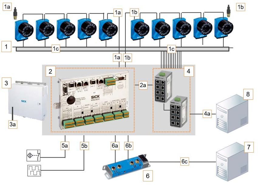
6.2 Connection Overview Lector654 - ALIS Camera
Fig. 24: Connection overview
1 Lector654
1a CAN 1 (CAN bus, 24 V voltage supply, incremental signal, terminator)
1b CAN 2 (CAN bus, 24 V voltage supply, incremental signal, terminator)
1c Gbit Ethernet
2 MSC800 system controller
2a Ethernet
3 Cabinet
3a Feed 230 V / 50 Hz
4 Ethernet switches
4a Gbit Ethernet (image output)
5a Trigger signal
5b Incremental signal
6 Field bus module (option)
6a 24 V voltage supply
6b RS232 data cable (MSC800 system controller - field bus module
6c Data output into PROFINET network
7 Customer's system
8 Image server (option)
8027605/V1-0/2022-03| SICK S Y S T E M D E S C R I P T I O N | ALIS 45
Subject to change without notice6 ELECTRICAL INSTALLATION
6.3 Connection Overview - ALIS RFID
Fig. 25: Connection overview
1 Read device RFU 630-041
1a TCP/IP
2 Antennas (3x with absorber module included and 1 for bottom reading)
2a Coax cabel
3 MCC800 system controller
4 Cabinet
4a Feed 230 V / 50 Hz
5a Trigger signal
5b Incremental signal
6 Field bus module (option)
6a 24 V voltage supply
6b RS232 data cable (MSC800 system controller - field bus module)
6c Data output into PROFINET network
7 Customer system
46 S Y S T E M D E S C R I P T I O N | ALIS 8027605/V1-0/2022-03| SICK
Subject to change without noticeCOMMISSIONING 7
7 Commissioning
Commissioning may only be performed by qualified persons.
● Qualified persons have the specialist training, skills, experience and knowledge of
the relevant regulations and standards needed to be able to perform work assigned
to them and to identify and avoid any potential dangers independently
● Electricians have the professional training, skills, experience and knowledge of the rele-
vant standards and provisions needed to work on electrical systems and to detect and
avoid any potential dangers independently
Initial configuration
The initial commissioning of the track and trace system is carried out by the manufacturer.
All of the system functions are set up by configuring the measuring conditions on-site.
Note
Initial commissioning by the manufacturer is not covered in these operating instructions.
8027605/V1-0/2022-03| SICK S Y S T E M D E S C R I P T I O N | ALIS 47
Subject to change without notice7 COMMISSIONING
48 S Y S T E M D E S C R I P T I O N | ALIS 8027605/V1-0/2022-03| SICK
Subject to change without noticeOPERATION 8
8 Operation
The track and trace system may only be operated by qualified persons.
Qualified persons have the specialist training, skills, experience and knowledge of the rele-
vant regulations and standards needed to be able to perform work assigned to them and
to identify and avoid any potential dangers independently.
8.1 System Start
▸ Set up the voltage supply for the cabinet.
▸ Connects the voltage supply for the MSC800 system controller and the connected sen-
sors.
▸ The sensors and controller are started up and checked for operational readiness in
a self-test.
Note
The white status LED on the cabinet lights up as soon as voltage is applied.
see chapter 8.2.5 MSC800 System Controller /page 50 and
chapter 8.2.6 System Readiness /page 50
The track and trace system is ready for use.
Note
The conveying system must be started by customer.
8.2 Check operational readiness
8.2.1 CLV691 Bar Code Scanner
Fig. 26: Operational readiness of the CLV691
● The Ready LED lights up.
8.2.2 CLV651 Bar Code Scanner
Fig. 27: Operational readiness of the CLV651
● The Ready LED lights up
8027605/V1-0/2022-03| SICK S Y S T E M D E S C R I P T I O N | ALIS 49
Subject to change without notice8 OPERATION
8.2.3 Lector654 Code Reader
Fig. 28: Operational readiness of the Lector654
● The Ready I Tst LED lights up.
8.2.4 RFU630
Fig. 29: Optical status indicators on the display
● The Ready LED lights up green
8.2.5 MSC800 System Controller
Fig. 30: Operational readiness of the MSC800 system controller
● The DEVIDE READY LED lights up
8.2.6 System Readiness
Fig. 31: System readiness
● In addition to the DEVICE READY LED, the SYSTEM READY LED also lights up on the
MSC800 system controller
50 S Y S T E M D E S C R I P T I O N | ALIS 8027605/V1-0/2022-03| SICK
Subject to change without noticeOPERATION 8
8.2.7 Automated Operating Mode
The track and trace system runs fully automated after startup. No manual intervention by
the operator is required
Minimum distance and rotational position
Fig. 32: Minimum distance and rotational position
Legend
1 ALIS Laser or Camera:
– minimum distance between bags >150mm
ALIS RFID:
– minimum distance between bags >400mm
2 ALIS Laser or Camera:
– minimum distance between two bar codes >50mm
ALIS RFID:
– minimum distance between RFID tags >400mm
3 Rotational position of bag and IATA code as desired
Note
If the bags rotate, vibrate, roll, or slip on the conveyor system and if the conveying sur-
faces are uneven, the read result may be affected.
8027605/V1-0/2022-03| SICK S Y S T E M D E S C R I P T I O N | ALIS 51
Subject to change without notice8 OPERATION
Several bags in reading field
Fig. 33: Several bags in reading field
● Several bags can be in the reading field
● The minimum distance must be upheld here
Not allowed
Fig. 34: No touching
● The objects must not be touching
● Otherwise the track and trace system will not deliver plausible read results.
8.3 System End
The conveying system is stopped by the customer.
8.3.1 Stopping the Conveying Syste,
▸ Wait until all objects have been processed.
Note
Do not stop the conveyor system if there is still an object in the reading area or if it enters
the reading area.
52 S Y S T E M D E S C R I P T I O N | ALIS 8027605/V1-0/2022-03| SICK
Subject to change without noticeOPERATION 8
8.3.2 Interrupting the Voltage Supply
▸ Interrupt the voltage supply to the cabinet.
The connected system components are now free from voltage.
Note
The white status LED on the cabinet is off.
8027605/V1-0/2022-03| SICK S Y S T E M D E S C R I P T I O N | ALIS 53
Subject to change without notice8 OPERATION
54 S Y S T E M D E S C R I P T I O N | ALIS 8027605/V1-0/2022-03| SICK
Subject to change without noticeMAINTENANCE AND REPAIR 9
9 Maintenance and Repair
Maintenance and repair measures may only be carried out by qualified persons.
● Qualified persons have the specialist training, skills, experience and knowledge of the
relevant regulations and standards needed to be able to perform work assigned to them
and to identify and avoid any potential dangers independently
● Electricians have the professional training, skills, experience and knowledge of the rele-
vant standards and provisions needed to work on electrical systems and to detect and
avoid any potential dangers independently
Device Maintenance task Interval[1] Staff
Trained
Lector654 Clean the viewing window 1x/month
personnel
Trained
CLV691 Clean the viewing window 1x/month
personnel
Trained
CLV651 Clean the viewing window 1x month
personnel
Check whether the fan is running and if air is coming out of the Trained
Radial fan Daily
blow-out nozzle personnel
Cleaning the air inlets and outlets Trained
Cabinet 4x/year personnel
Replacement of the filter mat in the air inlets and outlets
Trained
Visual monitoring for contamination Daily
personnel
Visual monitoring of conveying equipment for foreign bodies/ Trained
Daily
damage personnel
Whenever Trained
Control measurements with test objects to check the measure-
the system personnel
ment accuracy of the multi-dimensional measurement system
General is started
Trained
Visual inspection of the electrical cabling and wiring for damage 1x/year
personnel
Service
Maintenance of the individual components 2x/year
technicians
Checking the complete system including measurement system/ Service
1x/year
reading performance/image quality/reading range technicians
[1] The intervals depend on the ambient conditions and degree of contamination.
In addition, the intervals must be defined according to how important they are for the customer process.
8027605/V1-0/2022-03| SICK S Y S T E M D E S C R I P T I O N | ALIS 55
Subject to change without noticeYou can also read