Aircraft electrical system for carbon free flight - Technology review - Helmut ...
←
→
Page content transcription
If your browser does not render page correctly, please read the page content below
ETG-Kongress 2021 . ISBN 978-3-8007-5549-3 . ©VDE VERLAG GMBH . Berlin . Offenbach

Aircraft electrical system for carbon free flight – Technology review
Sean Dempsey, Airbus, Hamburg, Germany, sean.dempsey@airbus.com
Uwe Schliwa, Airbus, Hamburg, Germany, uwe.schliwa@airbus.com
Dr. Torben Schröter, Airbus, Hamburg, Germany, torben.schroeter@airbus.com
Prof. Dr. Detlef Schulz, Helmut Schmidt University, Hamburg, dschulz@hsu-hh.de

Abstract
The aviation industry sustains jobs, trade and tourism. The COVID-19 pandemic has been a systemic shock that has not
only halted air travel worldwide, but has made people reevaluate priorities, namely, our own health and safety and that of
our families, friends, and loved ones. Aviation plays a key role in this response. During the pandemic, we counted on
aviation for delivering vital air cargo services to boost global supply chains, evacuating stranded passengers, and enabling
time-critical life-saving emergency and humanitarian response missions. About 12 million passengers were carried on
every single day in 2018 [1]. Despite big external shocks it has experienced continuous growth [2]. However, two major
events in the last two years have significantly influenced this trend, Fridays for future and the Corona pandemic [3], [4].
These events have the potential to influence future aircraft (system) design. Game changer solutions to enable carbon free
flight, quick re-configuration and rate adaptation are required. Based on seven dimensions, the effect on the aircraft elec-
trical system due to the need for game-changer solutions will be evaluated. The results indicate that the effort in research
can be reduced in some dimensions while it is recommended to be increased in others.

1 Introduction reduce their carbon emissions to limit temperature rise and
 to meet the Paris agreement [7].
The aviation industry develops and sustains jobs and trade. In 2020, the COVID-19 pandemic spread all over the
It is vital lifelines to connect remote communities and world. Lockdowns in many countries made air traffic drop.
serves in rapid disaster response [1]. About 12 million pas- Data for the Eurocontrol network showed that the quantity
sengers (pax) and $18.8 billion worth of goods were carried of flights per day dropped from about 24000 down to about
on every single day in 2018 [1]. In that year, about 65.5 4000 flights per day within the second half of March 2020
million jobs were directly or remotely connected to air [4]. For about three months this low level was kept. After
transport [1]. These figures reflect a history of continuous a slight increase over summer 2020, new lockdowns cut the
growth of the aviation market. On the long run, it even had number of flights again with a similar course at global
been resilient to big external shocks e.g. 9/11 and the fi- level. This scenario has had a big impact on the objectives
nancial crisis in 2008 [2]. This continuous growth had been of the aviation industry. Furthermore, the pandemic en-
fostered by a few key developments, e.g. dropping average forced the need for flexible means of re-configuration of
price of air travel [1], evolution of the aviation industry into in-service A/C to enable re-sales in the aftersales market
new markets, evolving technologies and changing political demand on top of the existing demand for flexible re-con-
and legal systems. This has triggered a significant increase figuration [8, 9]. Altogether, this shows the urgent need for
of both passenger and air freight transport. From 1993 to “game changers” in A/C (system) development, in particu-
2015, the European aviation market has developed from lar to enable carbon free flight. Aircraft elements that have
360 to 918 million passengers [5]. Aircraft (A/C) and pro- the potential to become game changers require a coura-
duction system design have been guided by a dominant set geous leap from re-use to step-change development.
of value drivers. Besides safety, this set of drivers has in-
cluded fuel and cost efficiency, passenger comfort, revenue
increase, manufacturability at rate and sustainability. Two 2 The aircraft electrical system
major events in recent years have significantly influenced
 To describe the effect of the adapted importance of value
their weighting; Fridays for Future and the Corona pan- drivers on the A/C electrical system, its realisation on the
demic. A350 will be introduced first. It is one of the most modern
 electrical systems in service. Its architecture is shown in
Since 2019, the Friday for Future initiative has strongly af- Figure 1, see also [10]. During normal flight operations
fected the awareness of wide masses of human kind to act four 230 VAC Variable Frequency Generators (VFG), will
for a reduction of manmade carbon emissions. In the last supply the electrical network. In parking position, the A/C
800000 years, the carbon (CO2) average concentration in is either powered by the Ground Power Units (GPU), rated
the earth’s atmosphere has oscillated between 170 and 115 VAC, or by the Auxiliary Power Unit (APU), operated
300 parts per million (ppm) reached about 350000 years at 230 VAC (400 Hz). In an unlikely emergency event, the
ago [6]. In 1910, the value 300 ppm was reached again. 230 VAC Ram Air Turbine (RAT) generator will feed
Since then, this value has steadily risen to ~410 ppm in flight relevant loads [10]. Busbars are voltage-rated ac-
2019. Hence, it is imperative that industries significantly cording to the power source to which they are connected.
 Transformer Rectifier (TR) and Auto Transformer Units

 602
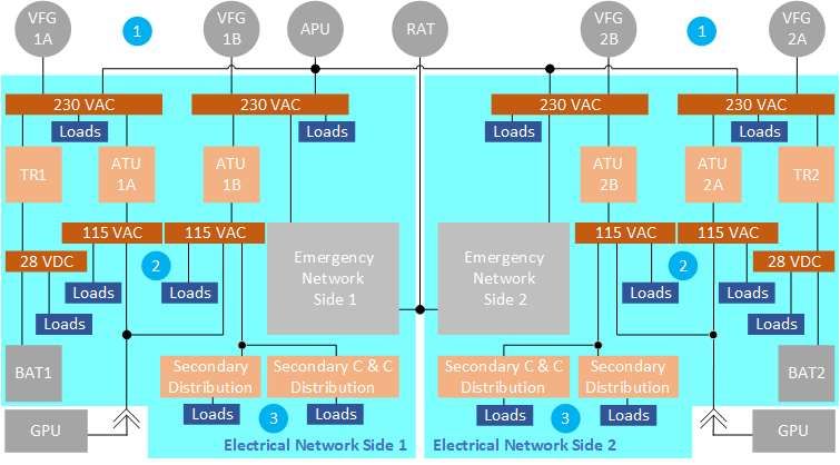
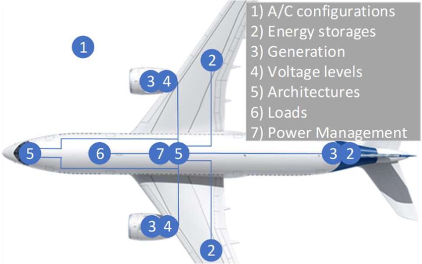
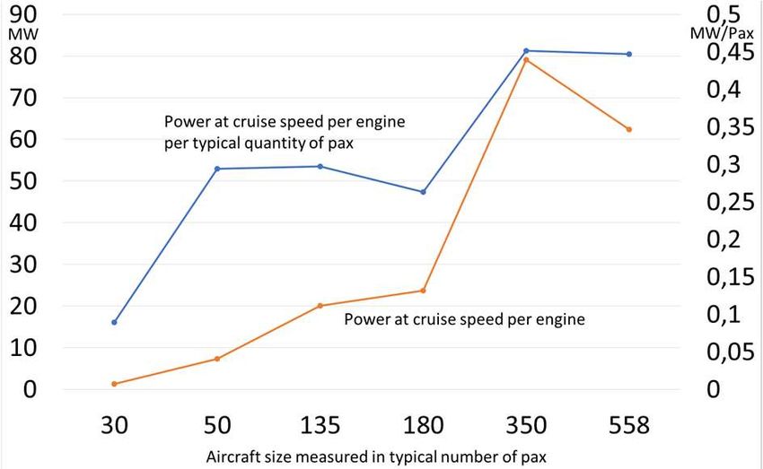
ETG-Kongress 2021 . ISBN 978-3-8007-5549-3 . ©VDE VERLAG GMBH . Berlin . Offenbach

(ATU) interconnect the different voltage levels. Electrical flight, on the design of the electrical system shall be con-
loads can be found on all voltage levels. With the introduc- sidered along seven dimensions; A/C configuration, energy
tion of the voltage level 230 VAC for high power electrical storages, electrical power generation, voltage levels, distri-
consumers, the A/C has significantly decreased weight. bution architectures, electrical loads, PM, see Figure 2.
Furthermore, with the carbon fibre fuselage, the return cur- The evaluation shall help review, for which components a
rent network and fast fuse protective functions (e.g. arc continuous evolution is sufficient, and for which ones a
fault detection) were introduced [10]. On either AC voltage game changing step is needed.
level, Load/Power Management Functions (PM) were im-
plemented to either protect the generators from damages or 3.1 Aircraft configuration
to govern the load on the respective wiring.
 The term “A/C configuration” shall refer to the A/C pro-
 gram, which directly implies characteristics such as system
 development epoch, architectures, geometry, structure ma-
 terials and mission. Figure 3 shows some A/C configura-
 tions with the specifics of the A/C electrical system. They
 show that further development has been dominated by con-
 tinuous evolution. In this paper the A220 will not be re-
 ferred to.

 Figure 1: The architecture of the Airbus A350 electrical
 system (with Power Management levels 1, 2 and 3)

In Figure 1 the generator level is marked with a 1, the main
distribution feeder level with 2. The “last-meter” distribu-
tion to the loads is marked with 3. Two new PM functions
were introduced on the A350 to achieve additional weight
reduction, see Chapter 3. Hence, the A350 electrical sys- Figure 3: Aircraft configurations & electrical system
tem has evolved in many aspects compared to previous
programs. In order to transition from evolutionary to revo- The objectives of emission free flight can impact the pro-
lutionary development, seven dimensions, depicted in Fig- pulsion system, energy sources and storages. In this con-
ure 2, shall be described, which characterize an A/C elec- text, the “thrust demand” has to be addressed. Figure 4
trical system. Chapter 3 will address their role in future shows the approximate absolute and relative (per pax) en-
A/C configurations. gine power for a couple of civil A/C of different size (by
 quantity of pax) for turbofan and turboprop A/C.

 [E1] = ∙ = ̇ − ̇

 According to E1, the net engine power P has been derived
 from the estimated engine net thrust force FN (at 80 % of
 full thrust) and typical cruise speed v per A/C, created
 through the difference of products of mass flows times ve-
 locity at the exit e of the engine and free stream f, assuming
 that the nozzle of jet engine is designed to equalize pressure
 difference [12, 13].

 Figure 2: The 7 dimensions of an A/C electrical system

3 The seven dimensions
As described before, besides safety, a set of value drivers
has dominated the decision making process in A/C (sys-
tem) design. Recently, high rate manufacturability became
more important. The Airbus announcement of the ZEROe
initiative re-enforced the ambition of sustainability and
emission free flight [11]. With three potential A/C config-
urations, addressing a mission envelop from less than 100
up to 200 pax and ranges from 1000 to 2000 nm, a wide Figure 4: Absolute and relative engine power vs. typical
scope of analyses will be performed. The effect of the shift A/C size (typical quantity per pax) - based on civil A/C
of the value driver weighting, in particular for carbon free developed between 1980s and today)

 603
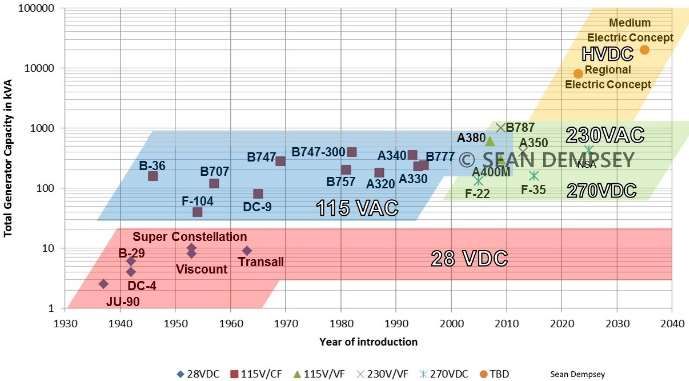
ETG-Kongress 2021 . ISBN 978-3-8007-5549-3 . ©VDE VERLAG GMBH . Berlin . Offenbach

3.2 Energy storage 3.3 Electrical power generation
Currently considered future energy storage systems for aer- Electrical power generation has seen evolutionary im-
oplanes are centred on jet fuel (or synthetic ‘e-fuel’), hy- provements over the last century of commercial aviation.
drogen and batteries. Jet fuel is considered the baseline for Airbus entered the market in the 1970s with the A300,
comparison. Carbon free options are (liquid) hydrogen and when the dominant electrical generator technology was the
batteries. While less polluting than jet fuel, both have con- Integrated Drive Generator (IDG). The IDG includes a me-
siderable disadvantages in terms of weight and/or volume chanical gearbox to run the electrical machine at constant
when compared with jet fuel. rpm to create a constant alternating current frequency of
 400 Hz. With the VFG, first introduced on the Airbus
Table 1 provides ‘fuel’ mass and volume for a given refer- A380, the gearbox is eliminated and the electrical machine
ence amount of energy1 to be stored in an A/C system by runs at variable speed and produces variable frequency AC
comparing jet fuel, hydrogen and battery options. The in- (360 Hz – 800 Hz) according to jet engine speed.
creased efficiency of an electrical propulsion system2 can
compensate for the actual amount of stored energy needed Research brought forward many different types of electri-
for the reference mission [15]. cal machines. Most IDGs and VFGs are three-stage syn-
 Liquid Li-Ion chronous machines. Lockheed-Martin has for example
 Jet Fuel Hydrogen Battery studied ‘switched reluctance machines’ for its 270 VDC
 electrical system [16]. Figure 5 charts the installed electri-
Specific energy in kWh/kg 12 39 0.5 cal generation capacity (and the main voltage level) for
Energy density in kWh/l 10 2.7 1
 many well-known military and civilian aircraft programs.
Energy required for For a carbon free aeroplane the three following electrical
reference mission 30 MWh 30 MWh 30 MWh
 generation options are considered: a) Hydrogen burning
Efficiency to thrust² 40% 60% 80% turbine engine with shaft driven electrical generator (‘H2
 burn’), b) Hydrogen to Fuel Cells as electrical generators
Required storage size due
to inefficiency 75.0 50.0 37.5 and c) Batteries as electrical power source

Required fuel mass in tons 6.3 1.3 75.0 A comparison of the potential electrical generation system
Required fuel volume for these three options is provided in Table 2. Only the ‘H2
in cubic meters 7.5 18.5 37.5 burn’ variant requires rotating electrical machines for
Table 1: Weight and volume comparison power generation, which could be integrated in the same
 manner as before into the engine nacelle. It also does not
While jet fuel only requires about six tons and seven cubic require propulsive electrical energy thereby eliminating the
meters, liquid hydrogen would require nearly three times need for multi megawatt class electrical systems. Only
the storage volume (18 m³) to contain just over one ton of about 5 % of overall energy needs to be converted for non-
fuel. The storage tank for liquid hydrogen requires thermal propulsive needs [17] and the electrical system footprint
insulation in order to keep the content in its liquid phase. can be kept relatively small. Depending on some other sys-
For batteries, even when assuming cells with 500 Wh/kg tem choices such as bleed-air extraction or hydraulic power
and 1000 Wh/l (not yet available), the mass and volume to generation (i.e. ‘More Electric A/C’), this configuration
store tens of MWh of energy is much larger. most closely resembles current aeroplanes and is the small-
 est carbon free electrical generation system.
When considering refuelling, liquid hydrogen can be
pumped, potentially achieving similar speeds as refuelling
with jet fuel. Batteries need to be swapped or recharged,
with either a significant cost and maintenance factor in case
of swapping or a significant effect on time and temperature
management as well as ground infrastructure in case of
(fast) charging (but a benefit of lower operating cost).

This simplified comparison shows the sensitivity of weight
and volume for the alternatively available ‘fuel’ choices.
The A/C electrical system on its own is unable to compen-
sate for the negative effects in weight. However, depending
 Figure 5: Generator Capacity & voltage level over time
on the modularity of the electrical system it might be able
to contribute to the additional space for larger tanks. Option b) is a very large fuel cell system covering the entire
 need for propulsive and non-propulsive electrical power

1 2
 For simplification reasons, 10MW for 3 hours, equaling 30MWh, is Electric powertrains are more efficient than combustion based ver-
selected for this reference mission energy amount sions. Batteries are more efficient than fuel cells. [14] The efficiency to
 thrust figures in this table are simplified assumptions to illustrate the dif-
 ference in energy storage size.

 604
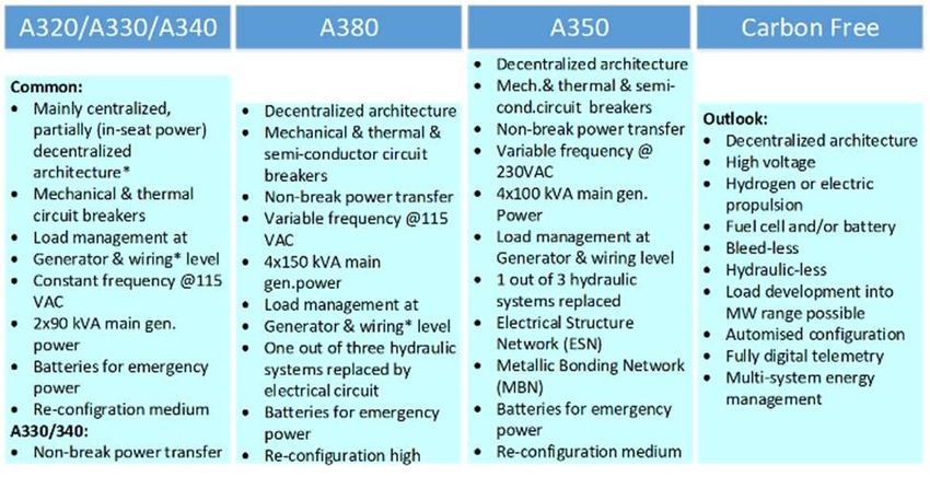
ETG-Kongress 2021 . ISBN 978-3-8007-5549-3 . ©VDE VERLAG GMBH . Berlin . Offenbach

and is therefore in the multi megawatt range. Bleed air ex- range. There are however some physical issues associated
traction and engine driven hydraulic pumps are not directly with high voltages that only come into effect in the aero-
possible, therefore all energy needs must be satisfied with space sector. The environmental conditions of high alti-
electricity from the fuel cell system. tudes with low ambient pressure can severely reduce the
 maximum voltage that can be used safely (see Paschen
Option c) is also a fully electric aeroplane. The clear dis- law). For internal compartments, there are failure modes
tinction is the different energy source in batteries making that can include sudden loss of pressurization. This has a
the system potentially reversible. However, both a) and b) significant effect on the required insulation of any high
consume fuel during the mission making the aeroplane voltage A/C electrical system.
lighter, whereas c) does not consume fuel, only ‘charge’.
 In summary, the selection of a distribution system nominal
 voltage for an A/C network largely depends on the required
 H2 burn Fuel Cell Battery power level. With a large range, from several hundred kil-
Propulsion Turbofan fully electric fully electric owatts to tens of megawatts considering the more electric
Energy Storage H2 in tank H2 in tank Batteries vs. the fully electric options, it is highly unlikely that a sin-
External O2 from out-
 gle nominal voltage can be selected to cover all needs. It is
component side O2 from outside n/a more likely that, in case of a fully electric propulsion sys-
Electrical rotating
 tem, the nominal voltage level will be in the kilovolt range
Generation machine electrochemical electrochemical (e.g. 10 kV) and a non-propulsive electrical system will
Electrical Sys- mostly
 continue to utilize the hundred volt range (e.g.
tem footprint unchanged very large extremely large 115 VAC). Game changing technologies such as active
Nominal less than 1V per Li-Ion ~4V per
 cooling or superconductivity possibly in combination with
Voltage design choice fuel cell cell a liquid hydrogen storage system could enable electrical
 serial circuit serial circuit
 distribution at lower voltages and higher currents than is
System Voltage design choice of cells of cells likely to be feasible today. The choice of voltage level has
 gas flow + par-
 the potential to be at least a differentiator to limit weight
 allel circuit of parallel circuit of increase in alternative energy source scenarios.
Power design choice stacks cells/modules
 3.5 Distribution architectures
Waveform AC DC DC
 This chapter will differentiate between the distribution ar-
Table 2: Carbon free electrical generation options
 chitectures of “common”, “more-electric” and “fully-elec-
 tric” aircraft. Most large commercial aircraft flying today
3.4 Voltage levels are built on common architecture rules, e.g. Airbus A320
Earliest A/C electrical systems relied on wind driven alter- to A380. Today, only a few more-electric large commercial
nators, as did the automobile sector (6 V or 12 V with aircraft are flying and fully-electric large commercial air-
power ratings of up to 1000 W). However, increasing craft are not existing.
power needs coupled with the requirement for low weight
led to the selection of 28 V as prevalent aviation standard On A320/A330/A340 the electrical power distribution is
[16]. designed from engine-hosted generators to a centralized
 primary/secondary/emergency power centre under the
With the introduction of jet engines, A/C became larger flight deck, then distributed for the cabin into two second-
and faster and required more electrical power. Crossing the ary distribution locations in the (front and aft) door areas.
~10 kW threshold led to the introduction of alternating cur- From these distribution points all loads are connected as a
rent (AC) generation in A/C to avoid large wire diameters. star. This leads to long supply wires and, for low voltage
28 VDC systems were retained for low power consumers, supply lines, often to very thick wires to limit voltage drop.
converter-powered from the higher voltage AC system. In On A350/A380 the secondary power distribution was de-
the 1940s, the US Army Air Corps selected what would centralized and distributed throughout the Aircraft in up to
later become an international standard (MIL-STD-704): 14 locations. This brings benefit for the length of last meter
115/200 VAC three phase systems at 400 Hz constant fre- connections of the loads and for wiring diameter [18].
quency with an increase of factor two to three in power
density of the generator system [16]. It could be expected that in the future, more levels of dis-
 tribution could be introduced, e.g. a tertiary or quaternary
As the power demand kept growing, the next new voltage level below the secondary power distribution from which
level deployed in civilian A/C was 230 VAC at variable aircraft manufacturers expect benefits in the area of device
frequency on the Airbus A350 and +/-270 VDC introduced design and configuration flexibility.
with the ‘More-Electric’ Boeing 787 (up to 1 MW power
demand). On the military side, the F-22 introduced a In case of an emergency, the distribution system of all cur-
270 VDC system in the early 2000s. rent Airbus aircraft models will be reconfigured and the
 APU or the RAT will supply all flight-relevant. For new
Future systems for electric propulsion with power demands Airbus A/C models the emergency reconfiguration could
in the ~10 MW area, consider voltages in the low kilovolt

 605
ETG-Kongress 2021 . ISBN 978-3-8007-5549-3 . ©VDE VERLAG GMBH . Berlin . Offenbach

be achieved in a different manner, depending on the se- on all A/C listed [17, 10, 23, 24]. The GCU together with
lected electrical power source types (H2, fuel cell, battery) the Overvoltage Protection Unit (OPU) is effective at level
and dependent on the inclusion of an electric propulsion 1 (Figure 1) in the electrical system. It manages the regu-
system (fully electric architecture), the second independent lation, performs overcurrent protection and ensures power
electrical power source could cancel the need of the RAT. demand limitation. In case of an overload, the generator
 will be disconnected from its circuit. An electrical network
For “More-Electric A/C architecture” the development of management function (ENMF), on A330/A340 the Electri-
electrical replacements for hydraulic and pneumatic as- cal Contactor Management Unit (ECMU), manages the
sisted equipment is foreseen, e.g. wing anti-ice, environ- (dis-)connection of the power sources from the main bus-
mental control system, flight controls. It is expected, that bar depending on their availability [10, 25, 26]. Further-
future architectures require previously separated systems more, on level 1 to avoid overload on generators and per-
to be more tightly integrated on a common platform, e.g. manent disconnection, the Electrical Load Management
the emergency lighting system, which is today inde- Function (ELMF) exists on the A340/A380/A350 [18, 10,
pendently battery operated. 26]. ELMF is able to shed non-flight relevant loads (e.g.
 galleys or other cabin loads) if the load exceeds a threshold.
3.6 Electrical loads Other than the GCU, ELMF can reconnect loads during
The A/C equipment evolved mainly with the introduction flight.
of new A/C models and state-of-the-art technologies. So,
even future A/C trends will bring new requirements and Managed Level in
 A320 A330 A340 A380 A350
 according to Figure 1
new challenges to adapt to, as well.
 GCU GCU GCU GCU GCU
The development of new technology which was already 1 - ECMU ECMU ENMF ENMF
 - - ELMF ELMF ELMF
adapted for A/C use due to higher efficiency are e.g. Light
 - - - - LPMF
Emitting Devices (for cabin lighting with 90 % power con-
sumption savings vs. incandescent lamp), flat screen (for 2
 PED-PM* PED-PM* PED-PM* PED-PM PED-PM

in-flight entertainment) and microwave ovens with re- - - - - Galley-PM
duced space demand in the galleys despite faster heating of
meals. Additionally, the electronic designs of aircraft 3 PED-PM* PED-PM* PED-PM* PED-PM PED-PM
equipment evolve to higher electrical power input stage ef- *(MCU) if In-Seat IFE/Power is installed
ficiency. The designs change from transformer-coupled to Table 3: PM functions on aircraft
switch-mode, which leads to a different load behaviour at
varied supply voltage levels. Most of this equipment be- To avoid increase of wiring weight proportional to the
have now as constant power devices. The equipment growth of non-flight relevant consumers, another three PM
weight and volume is reduced, accordingly. functions were introduced. They allow the over-installation
 of electrical loads on parts of electrical wiring at level 2
The next equipment evolution steps could be necessary, and 3 in Figure 1.
e.g. due to supply voltage changes which come along with
more efficient electrical distribution systems as well as new The Portable Electronic Devices PM (PED-PM) was ini-
energy generation and propulsion systems. In general, all tially introduced on the Airbus A320/A330 programs. It
aircraft equipment can be classified into 3 distinct was re-developed for the A380/A350 programs [10, 21,
groups: resistive load, motor load, electronic load. Each 26]. The newest PM functions are the Local Power Man-
group can be adapted to a new arising voltage level and/or agement Function (LPMF) and the Galley-PM3 [10, 21]. It
voltage form, accordingly in different manner and the ef- allows over-installation of the wiring between the main
fect on weight and volume depend on the consumed elec- power centre and the Secondary Power Distribution Boxes.
trical power. In addition, the Airbus more electric aircraft This function will do so by monitoring the actual current
projects will cover the evolution of non-cabin systems like on a feeder and shedding non-flight relevant loads, if the
ECS, brakes, flight controls, engine start, landing gear, current on the feeder exceeds the feeder maximum. Fur-
doors, anti-ice, as the energy source will be switched from thermore, it has a provision to control smart loads.
pneumatic/hydraulic to electric [18].
 Electrical PM functions will remain a crucial part of future
3.7 Power management aircraft electrical system generations. However, they might
Power Management (PM) functions have become an inte- not be more than a supportive element. The higher mass
gral part of the A/C electrical system, driven by a continu- and volume introduced e.g. by battery driven flight cannot
ous increase of electrical consumers. Their purpose is to be overcompensated by the weight reduction given by a
protect the respective managed level in the electrical sys- PM only. Neither has it been shown to have the potential
tem and to allow weight-optimization [19-22]. The follow- to strongly adapt the electrical system towards different
ing PM functions have been implemented on the A/C listed form factors to free up space. A potential exception might
in Table 3. The Generator Control Unit (GCU) is present be the battery PM itself to enable modular and distributed
 battery configurations.

3
 Non-ATA 24 function, not described in this paper

 606
ETG-Kongress 2021 . ISBN 978-3-8007-5549-3 . ©VDE VERLAG GMBH . Berlin . Offenbach

3.8 Role of dimensions in brief [5] European Commission: Mobility and Transport. https://ec.eu-
 ropa.eu/transport/modes/air/25years-eu-aviation_en, Brussels Au-
Based on the above descriptions, Table 4 summarizes the gust 30th, 2020
role of the seven dimensions. It shows that e.g. a function [6] Climate.gov: Climate Change: Atmospheric Carbon Dioxide.
like a PM function will yet be needed but might not have https://www.climate.gov/news-features/understanding-climate/cli-
 mate-change-atmospheric-carbon-dioxide. August 14th, 2020.
the potential to enable game changing solutions. However, [7] Masson-Delmotte, V., P. Zhai, H.-O. Pörtner et al: IPCC, 2018 Sum-
the dimension “energy storage” will certainly be a game mary for policy makers. In: Global Warming of 1.5°C, World Me-
changer. Others such as e.g. “voltage level” can be the tip- teorological Organization, Geneva, Switzerland, October 6th, 2018
ping point (differentiator) to feasibility in some scenarios. (also https://www.ipcc.ch/sr15/)
 [8] A. Shamshed, N. Hampson et al: Aviation Finance – Fasten your
Game changers and differentiator technologies do require seatbelts, PriceWaterHouseCoopers LLP,
a continued focus of innovation projects around the A/C https://www.yumpu.com/en/document/read/50364077/pwc-avia-
electrical system. tion-finance-fastern-your-seat-belts-pdf, page 30, January, 2013
 [9] G. Weissel, J. Luedeke: Best practices guide Cabin interior retrofits
 and entry into service program, IATA, page 7, February, 2019.
4 Summary & conclusion [10] Delta Airlines: Training Material ELECTRICAL POWER CH 24
 A350-900, January 1st, 2017.
A/C electrical systems have grown continuously with the [11] Airbus SAS: ZEROe, Towards the world first zero-emission com-
 mercial aircraft, https://www.airbus.com/innovation/zero-emis-
demand placed upon them, in power, voltage, size, com- sion/hydrogen/zeroe.html, January 14th, 2021
plexity, reliability. With the looming shift to carbon free [12] Wikipedia: Schub, https://de.wikipedia.org/wiki/Schub, January
energy transportation, the A/C electrical system is facing 10th, 2021.
new challenges. The review described in this paper has cut [13] T. Benson: General Thrust Equation, NASA Glenn Research Cen-
 ter, https://www.grc.nasa.gov/www/k-12/VirtualAero/Bot-
the A/C electrical system into seven dimensions and inves- tleRocket/airplane/thrsteq.html, January 10th, 2021.
tigated the potential of each dimension to foster the step- [14] AIAA Journal 52(5):901-911, A.H. Epstein, 2014, Aeropropulsion
change to carbon free flight. It turned out that the energy for commercial aviation in the twenty-first century and research di-
storage will make a big difference (game changer), while rections needed
the voltage level and the architectures can make a differ- [15] Valøen, Lars Ole and Shoesmith, Mark I. (2007). The effect of PHEV
 and HEV duty cycles on battery and battery pack performance
ence (to compensate for increased weight impact or volume (PDF). 2007 Plug-in Highway Electric Vehicle Conference
demand) when energy storages (including tank for liquid [16] IEEE: V. Madonna, Student Member, IEEE, P. Giangrande, and M.
hydrogen scenario) have reached the borderline to feasibil- Galea., Member, ‘Electrical Power Generation in Aircraft: review,
ity (e.g. sufficient energy density of batteries beyond 500 challenges and opportunities’
to 1000 Wh/kg). Research for the A/C electrical system [17] University of Nottingham: Prof. Pat Wheeler, ‘The More Electric
 Aircraft
should enforce its focus on the game changing and differ-
 [18] Moir, I. ; Seabridge, A.: Aircraft System : Mechanical, electrical and
entiator dimensions of the A/C electrical system. Further- avionics subsystems integration. 3th edition. West Sussex, Chich-
more, some other technology developments that are not ester : John Wley & Sons, Ltd., 2008. – ISBN: 978-0-470-05996-8
discussed here might also contribute to the future aircraft [19] Schröter, Torben; Schulz, Detlef: An Approach for the mathematical
electrical system design, e.g. the use of 3D printing parts Description of Aircraft electrical Systems’ Load Characteristics in-
with combined mechanical and electrical properties. cluding electrical Dependences Validation (IEEE International
 Conference on Electrical Systems for Aircraft, Railway and Ship
 Propulsion, ESARS Bologna 2010). IEEE. - ISBN 978-1-4244-
 Next generation 9093-6, reviewed paper, Document ID: FP112, pp. 1-6
ATA 24 Dimension Legacy aircraft Carbon free flight
 (e.g. eFuel)
 Electric [20] Schröter, Torben; Benstem, Torsten; Schulz, Detlef: Aircraft Avail-
 H2 burn ability and the Optimised Electrical System (3rd International
 (BAT&FC)
A/C configuration Defines the boundary conditions to solutions. Workshop on Aviation System Technology AST Hamburg 2011).
 In: von Estorff, Otto; Thielecke, Frank (editors): Proceedings of the
Energy storages S S GC GC
 3rd, International Workshop on Aircraft System Technologies.
Generator D S S N/A
 Aachen : Shaker, 2011. - ISBN: 978-3-8322-9904-0, pp. 3-12
Voltage level D D D D
 [21] Schröter, T.: Power Management on Aircraft, VDE Verlag GmbH,
Architecture D S D D
 Berlin/Offenbach, 2013, ISBN 978-3-8007-3510-5
Loads S S D D
 [22] D. Schlabe, J. Lienig: Energy Management of Aircraft Electrical
Power Management S S S S
 Systems - State of the Art and Further Directions, Conference:
Legend: Game Changer (GC), Technical Differentiator (D), Required Support (S) ESARS, At: Bologna, Italy October 2012,
Table 4: Role of the dimensions [23] Airbus Industries: 319/A320/A321 TECHNICAL TRAINING
 MANUAL MECHANICS / ELECTRICS & AVIONICS COURSE
 24 ELECTRICAL POWER
5 Literature [24] European Union Aviation Safety Agency: 2013-0175: Electrical
 Power– Generator Control Unit – Inspection, August 8th, EASA AD
[1] Air Transport Action Group (ATAG): Aviation Beyond Borders Re- No.: 2013-0175 2013
 port 2018. https://aviationbenefits.org/media/166711/abbb18_full- [25] Airbus S.A.S.: A380, G MANUAL, MAINTENANCE COURSE -
 report_web.pdf. October 10th, 2020 T1 & T2 (RR / Metric), LEVEL III - ATA 24 Electrical Power
[2] Airbus SAS: Global Market Forecast - Cities, Airports and Aircraft [26] Lufthansa Technical: A330/A340 ATA 24 L2E Electrical Power
 2019-2038, Blagnac Cedex, France, 2019, ISBN 978-2-9554-382- ATA Spec 104 Level 3
 4-6
[3] Airbus SAS: Decarbonisation. https://www.airbus.com/company/sus-
 tainability/environment/decarbonisation.html, October 12th, 2020
[4] Eurocontrol - Aviation Intelligence: Daily Traffic Variations.
 https://www.eurocontrol.int/Economics/DailyTrafficVariation-
 States.html, August 30th, 2020

 607
You can also read