AAA-RO50W AAA-RO100W - RO Drinking Water System Installation Guide & Owner's Manual - WaterAnywhere
←
→
Page content transcription
If your browser does not render page correctly, please read the page content below
RO Drinking Water System
   Installation Guide & Owner’s Manual

                                              AAA-RO50W
                                             AAA-RO100W
www.wateranywhere.com   (760) 727-1652   sales@wateranywhere.com   Document ID #: AAAROW
                                                                      Revision: 05/13/20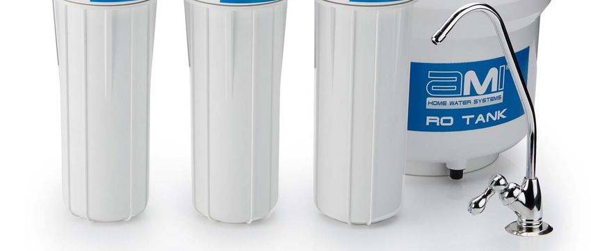
Installation Guide & Owner’s Manual – Under-the-Counter Reverse Osmosis Drinking Water System
About Your RO Water Treatment System
Thank you for your purchase of the WaterAnywhere home RO reverse osmosis water treatment system. This
drinking water system has been designed for quick and simple installation and maintenance. By carefully
reading this instruction manual and following the operational guidelines you will ensure a successful installation
and reliable operation. Routine maintenance is essential to the longevity and performance of the system.
Filters should be changed every three to six months depending on the quality of the feed water supply.
Notice: Please read this entire service guide prior to beginning installation.
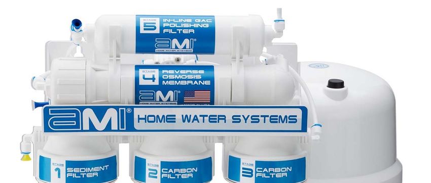
5 Stages of Water Treatment
Stage1: Sediment Filter Cartridge Replace every 3-6 months
The first filter the water passes through is a five micron filter cartridge. This cartridge removes
sediment including dirt, sand, rust, grit, and other suspended matter from water. This protects the rest
of the filtration stages and equipment from damage and clogging due to buildup of sediment.
Stage 2 & 3: Carbon Block Filter Cartridges Replace every 3-6 months
Next, the water passes through two stages of carbon filters to remove chlorine and objectionable tastes
and odors from water. These filters also protect the membrane from exposure to chlorine, which would
irreparably damage the membrane.
Stage 4: Reverse Osmosis Membrane Replace every 12 months
The fourth stage is the reverse osmosis membrane, which is the heart of the RO system. The RO
membrane substantially reduces the total dissolved solids (TDS) from the water, including arsenic,
barium, cadmium, chromium (hexavalent), chromium (trivalent), copper, turbidity, fluoride, lead, radium
226/228, and selenium, while washing the rejected contaminants down the drain. The treated water is
directed to the storage tank.
Stage 5: Post Carbon Filter Replace every 3-6 months
The last stage of filtration occurs as the water flows from the storage tank directly before being
dispensed from the faucet. The in-line carbon post filter (also known as polishing filter) removes any
remaining tastes or odors from the water, improving the flavor.
Replacement frequency varies based upon incoming water quality and use patterns.
Notice: Generally speaking, filters should be changed when there is a loss of performance or
after an extended period of non-use.
System On/Off Valves
Your RO System is equipped with two on/off ball valves. The system feed valve (to be installed into the cold
water supply line) can be used to turn the water to the system on and off for maintenance without disrupting
the water supply to the sink. The tank valve can also be closed to prevent water in the tank from draining out
during maintenance. Both can be opened by turning counterclockwise, and closed by turning clockwise.
System Feed Valve in System Feed Valve in Tank Valve in Tank Valve in
OPEN Position CLOSED Position OPEN Position CLOSED Position
Copyright © 2020 WaterAnywhere Page 1
All Rights Reserved.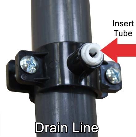
Installation Guide & Owner’s Manual – Under-the-Counter Reverse Osmosis Drinking Water System

Table of Contents

About Your RO Water Treatment System .........................................................................................................1
   5 Stages of Water Treatment ............................................................................................................................1
   System On/Off Valves .......................................................................................................................................1
Conditions for Operation ...................................................................................................................................3
Warnings .............................................................................................................................................................3
System Flow Diagram ........................................................................................................................................4

Preparing For Installation ..................................................................................................................................5
   Recommended Tool List: ..................................................................................................................................5
   Check Location .................................................................................................................................................5
   Assemble Filter Housings onto System Manifold ..............................................................................................5
   Prepare Tubing .................................................................................................................................................6
   Quick Connect Fittings and Tubing Connections ..............................................................................................6

Installation Steps
Step 1 - Drill a Hole into the Sink for the Faucet ..............................................................................................7
Step 2 - Faucet Installation ................................................................................................................................8
Step 3 - Drain Saddle Installation ......................................................................................................................9
Step 4 – System Feed Line Installation ..........................................................................................................10
Step 5 – Installing the RO Storage Tank.........................................................................................................12
Additional Point of Use Connection (Optional) .............................................................................................12
System Mounting ..............................................................................................................................................13

Turning the System On for the First Time ......................................................................................................13
Replacement Parts ...........................................................................................................................................14

System Maintenance ........................................................................................................................................15
   Membrane Replacement Instructions .............................................................................................................15
   Filter Replacement Instructions .......................................................................................................................15
   Sanitizing.........................................................................................................................................................15

Troubleshooting Chart .....................................................................................................................................16

Maintenance Schedule and Log……………………………………………………………………………………...20

 Copyright © 2020 WaterAnywhere                                        Page 2
 All Rights Reserved.
Installation Guide & Owner’s Manual – Under-the-Counter Reverse Osmosis Drinking Water System

Conditions for Operation
  Source Water Supply
  Community/Private                       Non-Chlorinated – or chlorinated as long as the carbon filter is in place
                                          and replaced every 6 months. Chlorine will damage membranes if not
                                          removed properly.
  System Pressure                         40 psi minimum - 90 psi maximum
  Temperature                             4º-38º C (40º-100º F)
  Maximum Supply TDS Level                1500 ppm (mg/L)
  Turbidity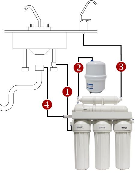
Installation Guide & Owner’s Manual – Under-the-Counter Reverse Osmosis Drinking Water System

System Flow Diagram
   A    Water supply to the first housing                      J   Faucet
   B    Water supply to the second housing                     1   Clean Water Outlet
   C    Water supply to the third housing                      2   Pollutants Outlet
   D    Housing with the RO Membrane                           3   Water Supply to the 4-way valve from the elbow
   E    Four-way Valve                                             connector “OUT” in the third housing
                                                               4   Clean water supply to the 4-way valve through the
   F    In-Line Cartridge with Activated Carbon                    membrane
   G    Flow Restrictor                                        5   Water outlet from the valve to the membrane
   H    Tank Valve                                             6   Clean water outlet from the valve to the in-line cartridge
   I    Tank                                                       with activated carbon
                                                           -

 Copyright © 2020 WaterAnywhere                   Page 4
 All Rights Reserved.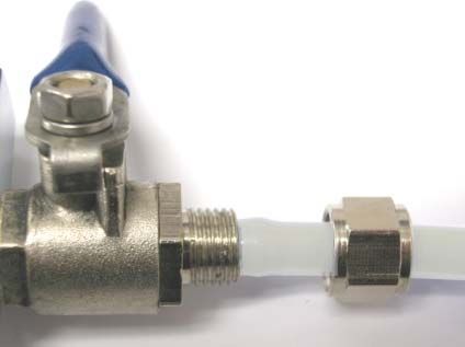
Installation Guide & Owner’s Manual – Under-the-Counter Reverse Osmosis Drinking Water System
Preparing For Installation
Check the following list of components to ensure that all parts are packed with your system.
RO System Filter Housing Filter Cartridges
Manifold Assembly Sumps (Packed in Sumps) Storage Tank Faucet Kit
Feed Adapter Kit Filter Wrench
Drain Saddle (1/2” & 3/8”) Tank Valve Membrane Wrench White Tubing
Recommended Tool List:
Have the below tools on hand before beginning installation. These are not included with the system.
Electric drill with ⅛”, ¼" & 7/16” drill bits Phillips screwdriver
1-¼” hole saw bit for faucet opening – appropriate for the surface Utility knife
you are drilling Teflon tape (included)
½” and 7/16” open-end wrenches (or two adjustable wrenches) Masking tape or duct tape
Mounting screws or anchors appropriate for the surface you are
mounting to
Check Location
Determine the location for the installation of the RO system. Avoid locations where the system might come
in contact with hot water pipes or other hazards.
Determine the location of the cold water feed line to use for the system supply.
Notice: Accidentally hooking up the system to the hot water supply line will permanently
damage the membrane (see conditions for operation). To assure you are using the
cold water line, turn on both the hot and cold faucet. After the water is warm to the
touch, feel the pipes under the sink. It will be easy to identify the hot and cold pipes.
Determine the location for the faucet. Check to see that drilling the faucet hole will not damage pipes or
wires running underneath the sink.
Determine the location for the storage tank. A maximum distance from tank to faucet of 15 feet is possible
(additional tubing will be needed). The system will produce a faster flow at the faucet with the shortest
tubing run from tank to faucet.
Assemble Filter Housings onto System Manifold
Remove the plastic wrapping from the filter cartridges and insert each cartridge into a filter sump.
Making sure the o-ring stays seated properly, screw the filter sump onto the appropriate cap. The filters
should be installed in the following order of flow (left to right):
(1) Sediment Filter H-F1005CF (2) Carbon Filter H-F2510AC (3) Carbon Filter H-F2510AC
Check to ensure the sump is tightly threaded onto the housing.
Copyright © 2020 WaterAnywhere Page 5
All Rights Reserved.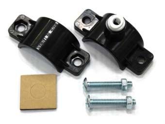
Installation Guide & Owner’s Manual – Under-the-Counter Reverse Osmosis Drinking Water System
Prepare Tubing
When cutting tube lengths, it is important to ensure the system is
accessible for maintenance. During installation and measuring, it is
recommended to complete all of the tubing connections to the system
with the system in front of the cabinet (before mounting) to allow enough
slack for easy removal of the system for easier maintenance.
Measure and cut (4) lengths of tubing in the appropriate lengths for:
Feed line to system pre-filter inlet
Post filter inlet (tee) to tank
Post filter outlet (elbow) to faucet
Membrane outlet flow restrictor to drain
Quick Connect Fittings and Tubing Connections
To ensure a secure seal using quick connect fittings:
Cut tubing with the end square. An angled cut or distortion of the
tubing will not provide an efficient seal and may cause leaks.
Remove blue locking clip from fitting before installing tubing. Push
down on the fitting collet and remove the plug. Keep the clip. The plug
may be discarded.
Push the tubing into the fitting, to the pipe stop. The collet (gripper)
has teeth which hold the tubing firmly in position while the 'O' Ring
provides a permanent leak proof seal.
Check the Seal: Pull on the tubing to check it is secure. It is good
practice to test the system prior to leaving site and/or before use.
Replace blue locking clip after tubing is installed.
To Disconnect: Ensure system is depressurized before removing
fittings. Push in the collet against the face of the fitting. With the collet
held in this position the tube can be removed. The fitting can then be re-
used.
Copyright © 2020 WaterAnywhere Page 6
All Rights Reserved.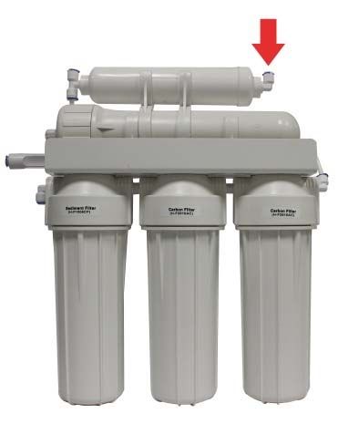
Installation Guide & Owner’s Manual – Under-the-Counter Reverse Osmosis Drinking Water System
Step 1 - Drill a Hole into the Sink for the Faucet
If your sink is equipped with a pre-drilled 1 ¼” or 1 ½” hole suitable for the faucet
Notice: installation, you may skip to step 2.
Notice: Manufacturer assumes no responsibility for damages resulting from installing faucets
into any surface. It is recommended to use a licensed contractor for this step.
For this, step, you will need:
Masking tape or duct tape
Variable speed drill with ⅛” and 7/16” drill bits
1-¼” hole saw bit for faucet opening – appropriate for the surface you are drilling
Determine the desired location for your RO Faucet
The product water faucet may be installed on any flat surface at least 2” in diameter. Check the underside
of the location for interference. The standard faucet that is supplied with the system requires a ½” diameter
hole. The optional air-gap faucet requires a larger hole of ¾” to allow for the additional tubing connections
required.
Stainless Steel Sinks
Begin by placing a piece of masking tape or duct tape on the determined location where the hole is to be
drilled. Make a small indent to mark the desired drilling location using a center punch. Drill a pilot hole with
a ⅛” metal drill bit. Enlarge the hole using a ¼” metal drill bit, using factory approved method or approved
plumbing practice.
Porcelain/Enamel Sinks or Tile Countertop
Sinks of this type are very easy to damage due to the nature of the materials of construction. A successful
installation into these sinks requires a knowledgeable technician with the proper cutting tools. We strongly
recommend the use of a “Relton” type device. Follow the directions that accompany the tool carefully.
Copyright © 2020 WaterAnywhere Page 7
All Rights Reserved.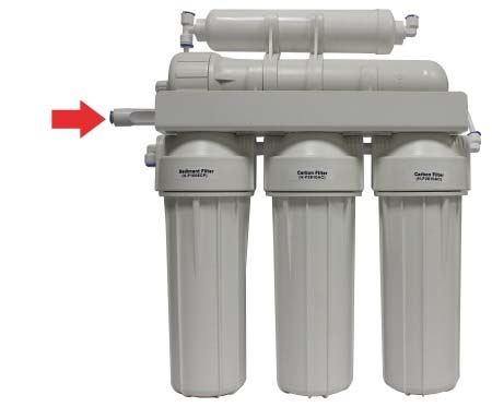
Installation Guide & Owner’s Manual – Under-the-Counter Reverse Osmosis Drinking Water System
Step 2 - Faucet Installation
For this step, you will need:
Faucet assembly kit included with System
Tubing, cut to the appropriate length
Wrench
Install the faucet onto the
countertop/sink:
Find and identify all of the parts in the faucet bag, as
shown in the diagram.
Add the metal washer (2), and then the rubber seal
(3) onto the threaded nozzle of the faucet (1).
Place the faucet nozzle through the previously drilled
hole in the countertop or sink top, and let it rest on the
sink top.
From the underside of the sink, slide the washers
onto the threaded stem as shown in the diagram.
- (4) & (5) - made of rubber
- (6) - made of metal
Secure the assembly by threading on the locking nut
(7).
Check the orientation and alignment of the faucet and
washers, adjust as necessary, then use a wrench to
tighten the locking nut securely
Notice: Do not overtighten fittings.
Install the Tubing
Slide the metal nut (10) over the end of the tubing
with the threads facing up.
Add the plastic clamp (9).
Press the plastic insert (8) into the end of the tubing.
Slide the tubing (until it
stops) inside the faucet
nozzle and screw it in by
hand with the nut that was
placed on the tubing earlier
(10).
Connect the other end of
the tubing to the elbow in
the “out” end of the post
filter.
Copyright © 2020 WaterAnywhere Page 8
All Rights Reserved.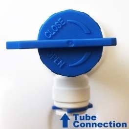
Installation Guide & Owner’s Manual – Under-the-Counter Reverse Osmosis Drinking Water System

Step 3 - Drain Saddle Installation

                   Some states require the use of an air gap faucet. Check your local plumbing code to
  Notice:          assure compliance.

For this step you will need:
        o   Masking tape or duct tape
        o   Variable speed drill w/ ⅛” and ¼" drill bits
        o   Phillips Screwdriver
        o   Drain saddle assembly supplied with system
        o   White tubing cut to appropriate length

Select Location for Drain Saddle Installation

Select a location for the drain hole based on the design of the plumbing.       It should be installed above the trap
and on the vertical or horizontal tail piece.

      Notice:        Do not install downstream of a garbage
                     disposal, as this can cause
                     contamination and system fouling. Install
                     onto a drain location without a garbage
                     disposal.

Drill a ¼” Hole in the Drain Pipe
Starting with the ⅛” drill bit, drill a ⅛” hole in the drain pipe. Use the ¼” drill bit to enlarge the hole. Clean the
debris from the pipe and the hole before continuing.
 Copyright © 2020 WaterAnywhere                    Page 9
 All Rights Reserved.
Installation Guide & Owner’s Manual – Under-the-Counter Reverse Osmosis Drinking Water System
Notice: Take extreme caution to not drill through to the other side of the drain pipe.
Install the Drain Clamp
Apply the foam gasket inside the front half of the drain saddle: Punch out the cut-out hole in the center of
the pad, remove the adhesive backing, and adhere to the inside of the drain saddle, ensuring the holes
are aligned.
Place one half of the plastic drain saddle assembly on each side of the drain pipe with the fitting, and
clamp loosely using the nuts and bolts included.
Align the hole drilled in the drain pipe with the hole in the drain saddle. A drill bit or other long narrow
object may be used to help align correctly.
Use Phillips screwdriver to tighten the clamp. Avoid over-tightening.
Connect Drain Line to RO System Reject Line
Insert tubing to the pipe stop in the quick connect fitting on the drain line and check the seal.
Connect the other end of the tubing to the flow restrictor outlet coming from the membrane brine port.
Step 4 – System Feed Line Installation
For this step you will need:
½” and 7/16” open-end wrenches (or two adjustable wrenches)
Teflon Tape
Feed Adapter (in the size that matches your feed line) & Ball Valve Kit
Tubing
Locate and Turn Off the Cold Water Supply
Locate the valve in the cold water feed line you use for the supply.
Copyright © 2020 WaterAnywhere Page 10
All Rights Reserved.Installation Guide & Owner’s Manual – Under-the-Counter Reverse Osmosis Drinking Water System
Accidentally hooking up the system to the hot water supply line will permanently
Notice: damage the membrane (see conditions for operation). To assure you are using the
cold water line, turn on both the hot and cold faucet. After the water is warm to the
touch, feel the pipes under the sink. It will be easy to identify the hot and cold pipes.
Close the cold water valve.
Turn on the sink faucet to drain water and relieve pressure from the lines.
If no shut off valve is located under the sink, or if water continues to come out of the faucet, turn off the
main supply at the entry to the house, then turn on the sink faucet to drain water and relieve pressure from
the lines.
Assemble the Ball Valve & Adapter Kit
Identify your line size and use the appropriate feed adapter (3/8” or 1/2"”). The extra feed adapter is not
needed.
Use Teflon tape to wrap the threads of the ball valve – approximately 3 wraps.
Screw the ball valve into the adapter.
Install the Feed Adapter into the Cold Water Supply
Wrap the slip joint adapter with Teflon tape, approximately 3 wraps.
For Flex Line: Loosen nut and separate cold water riser tube from faucet shank.
Gently bend riser rube so that slip joint fits onto faucet shank. Make sure the flat
washer is on top and the cone washer is on the bottom. Reinstall riser tubes onto
slip joint adapter and tighten.
For Solid Copper Riser Tube: Same procedure as flex tubing except you must
cut a piece of the riser tube about ¾” to 1” so the slip joint adapter can fit between
faucet and riser tube.
Connect the Feed Line Tubing
Unscrew the nut from the ball valve. Slide the nut onto the tubing, threaded
sides facing the end of the tubing. Feed the nipple on the ball valve into the
tubing, pushing the tubing until it slides over the lip. Slide the nut to the
threads on the ball valve, and tighten the nut down over the tubing. Use a
wrench to tighten ¼ turn past finger-tight.
Connect the other end of the tubing to the feed port on the RO System.
Copyright © 2020 WaterAnywhere Page 11
All Rights Reserved.Installation Guide & Owner’s Manual – Under-the-Counter Reverse Osmosis Drinking Water System
Step 5 – Installing the RO Storage Tank
For this step you will need:
Storage Tank
Tank Valve
Tubing
Do not tamper with the air valve on the low side of the storage tank. It has been
Notice: factory charged to 8psi and covered with a black cap.
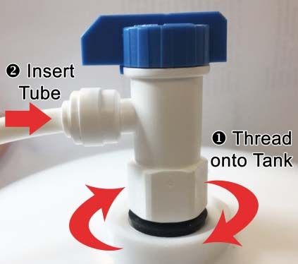
Install the Tank Valve & Tubing
Remove the blue cap on top of the tank to expose the
threaded in/out connection. Connect the tank ball valve
by threading onto the fitting. Do not over-tighten.
Notice: Do not add teflon tape to the tank
fitting. This will prevent seals from
engaging and may cause leaking.
Insert the tubing into the quick connect fitting on the ball
valve.
Connect the other end of the tubing to the inlet tee of
the post-carbon filter on the RO system.
Additional Point of Use Connection (Optional)
Ensure that all tubing and fittings used for RO product water are poly material, and not
Notice: copper. Due to RO product water being very pure, it can leach the minerals from
copper tubing which will cause a metallic taste in the water or ice and cause the
copper tubing to develop pinhole leaks over time.
An additional connection may be made to other equipment such as an icemaker, refrigerator, coffeemaker, or
other equipment. This requires an additional tee fitting and extra tubing. It is also strongly recommended to
install an in-line ball valve between the RO system and the equipment, to be closed during startup and
maintenance.
Suggested Parts
¼” Union Tee ¼” Tubing (10 Feet) ¼” In-Line Ball Valve
Part Number: PI0208S Part Number: TUBE-10FT-14-WH Part Number: PPSV040808W
Installation
Cut tubing between the faucet and the outlet of the post-filter. Insert the line into both branches of the tee.
Run line from the stem of the tee to the equipment and connect according to manufacturer’s instructions.
Install the ball valve in an accessible location on the line by cutting the line and inserting the tubing into
both sides of the ball valve.
Copyright © 2020 WaterAnywhere Page 12
All Rights Reserved.Installation Guide & Owner’s Manual – Under-the-Counter Reverse Osmosis Drinking Water System
System Mounting
Wall mounting is recommended for this system. Dry wall anchors and screws may be necessary (not included
with the system).
Mark screw locations at the desired positions. Use the two holes on the back of the RO System mounting
bracket for marker guides.
Screw the screws into the mounting wall on the marked positions. Use an anchoring device appropriate for
the type of material you are screwing into.
Hang the purification system onto the screws by the holes on the back of the unit.
Turning the System On for the First Time
Make sure all water supply and drain line connections are secure and free from leaks.
Slowly turn the feed valve counterclockwise until fully open (the handle should be in line with the tubing as it
enters the connection). Check the stem seal for leakage. If necessary, tighten stem nut lightly.
Turn storage tank valve one quarter turn counterclockwise to open the valve (the handle should be in line with
the tubing as it enters the connection).
Open the product water faucet and let the water flow until all the air has been expelled from the system. This
will take about an hour.
Close the product water faucet. In 30 minutes, check the system and connections for leaks and correct if
necessary.
Do Not Use the First Two Reservoirs of Water
Allow the reservoir to fill for 4-6 hours. Dispense this water to drain. This process
removes the factory installed sanitizing solution from the entire system and sends it to
the drain. Repeat this process one more time. Allow the tank to fill for 4-6 hours and
dispense this water to the drain. Do not drink this water!
Air bubbles may be present in the product water after initial system startup, causing a
Notice: milky color in the water. This is normal and safe to drink. The air bubbles will
disappear within a few days of regular use.
Notice: Check back frequently in the first 24 hours to ensure no leaking has occurred.
Copyright © 2020 WaterAnywhere Page 13
All Rights Reserved.Installation Guide & Owner’s Manual – Under-the-Counter Reverse Osmosis Drinking Water System
Replacement Parts
Sediment Pre-Filter, Carbon Pre-Filter, Replacement Filter Kits:
5 Micron. Extruded Carbon
Stage 1 Stage 2 & 3
Model: H-F1005CF Model: H-F2510AC
Qty. 1 Per System Qty. 2 Per System
Replace every 3-6 months Replace every 3-6 months
Membrane Element Carbon Post-Filter,
Stage 4 GAC Inline RFK-5: Pre & Post Filters
Stage 5 RFK-5-PRE: Pre-Filters Only
Model:
50 GPD: M-T1812A50 Model: H-F10GAC-14 RFK-5-50 (50 gpd)
100 GPD: M-T1812A100 Qty. 1 Per System RFK-5-100 (100 gpd)
Qty. 1 Per System Replace every 3-6 months One complete set of prefilters, post
Replace every 12 months filter, and membrane.
See back cover for replace schedule.
Other Replacement Components
Part Image Part Image Part Image
TUBE-10FT-14-WH
White Tubing
H-H14FWWA 10 foot pack
H-T5000
Filter Housing Faucet, Non-Airgap,
Standard 10”
PN-4-P
Long-Reach
White, ¼” FNPT ¼” Hex Nipple
(connects filter housing
to filter housing)
H-V1050W-QC F-4MBT44QC
PV2012PME
Auto Shut-Off Valve ¼” Male to ¼”QC
Membrane Housing Branch Tee (for post
⅛” FNPT filter inlet)
H-S3200TV PI480822S
Tank Shut-Off Valve Elbow Fitting
¼” MNPT × ¼” QC (for
H-S3200PW
filter housings & post
Storage Tank filter outlet)
3.2 gallon
H-V1009
Feed Valve and PI480821S
Adapter Elbow Fitting
⅛” MNPT × ¼” QC (for
H-R2068QC membrane housing)
50 GPD Flow Restrictor
H-R1000QC H-D3000M H-V1003
100 GPD Flow Restrictor Drain Saddle Check Valve, installed
in ¼” Elbow
H-J2021KW (membrane permeate)
Clip, Membrane Housing H-C9200FWWA
to In-line Filter Wrench for Filter
Housing
H-B2031W
H-J2025PW OR-H10FWWA-SET
O-Ring Set for Filter Mounting Bracket
Clip, Membrane Housing
to Bracket Housing. Top &
Bottom.
Copyright © 2020 WaterAnywhere Page 14
All Rights Reserved.Installation Guide & Owner’s Manual – Under-the-Counter Reverse Osmosis Drinking Water System
System Maintenance
If your RO system is connected to an icemaker or other equipment, you must turn off
Notice: the connection to the equipment before performing any maintenance.
Membrane Replacement Instructions
The membrane should be replaced every 1-2 years, depending on the water quality.
Before starting, shut off the cold water supply to the unit. Lift the handle on the faucet to drain out the storage
tank completely and allow the system to stand for 10 minutes in order to fully decompress the tank. Leave the
faucet open until the membrane change is complete.
1. Unscrew the fitting to the cap of the membrane housing. Use the membrane wrench if the cap is too tight.
2. Using pliers, pull out the old membrane from the housing.
3. Remove the new membrane from its bag.
4. Insert the membrane in the housing in the same direction as the old membrane.
5. Push the membrane firmly into the housing until it seats on the far end.
6. Screw the housing cap back on, making sure the o-ring is positioned correctly.
7. Screw the fitting (with tubing) back onto the housing.
8. The system is ready. Turn on the water supply. Check for any leaks.
9. Drain the first two tanks of water before drinking.
Filter Replacement Instructions
All pre and post-filters should be replaced every 3-6 months.
Before starting, shut off cold water supply to unit. Lift the handle on the faucet to drain out the storage tank
completely and allow the system to stand for 10 minutes in order to fully decompress the tank, reserving some
of the RO water to use to rinse the filter housings. Leave the faucet open until the filter change is complete.
1. Remove pre-filters from filter housings. Use a filter wrench if the housings are too tight.
2. Discard used filters, but save o-rings for re-use.
3. Clean inside of all housings with a mild soap solution, and then rinse with RO water.
4. Lubricate the o-ring and replace in filter housing.
5. Insert the new filters into the appropriate housings and replace the housings onto the system.
6. Disconnect the post-filter by removing the fittings on either end. Replace with new post-filter and re-use
the existing fittings. (Feed end tee is connected by a short length of tubing, remove this and use to connect to new filter.)
7. Follow the normal Start-up Procedures. (Drain the first tank of water after changing the filters before
drinking.)
Sanitizing
We recommend sanitizing the system at least once a year. This can be done while changing your filters. Shut
down the system. If you have an icemaker hook-up installed, be sure the ball valve in the line to the
refrigerator is in the closed position during this procedure. Open the faucet to drain the system, including the
tank. Remove the pre-filter cartridges and RO Membrane from the system, leaving the old post-filter cartridge
in place. Wash the internal filter housing & membrane housing areas with warm soapy water and rinse well to
remove the soap. Pour about ¼ teaspoon of Hydrogen Peroxide or household bleach into each filter housing
and replace housings on the RO system. Open the feed water valve and open the RO faucet until water flows
freely from the spout. Close the faucet and hold the solution in the system for a minimum of 10 minutes.
Drain the tank completely, close the faucet to allow tank to fill again, and then drain again. Replace filters and
membrane as indicated in the replacement instructions. The post filter should be changed after sanitizing the
system.
Copyright © 2020 WaterAnywhere Page 15
All Rights Reserved.Installation Guide & Owner’s Manual – Under-the-Counter Reverse Osmosis Drinking Water System
Troubleshooting Chart
Symptom Possible Cause Remedy
No water in the storage Filter Cartridges have failed. Replace filter cartridges as indicated in
tank maintenance section.
Cartridges are out of Install cartridges in proper sequence as
sequence. indicated in system components.
Cartridges are upside-down. Install carbon block filter right-side-up as
indicated on the filter.
No pressure in storage tank. Check pressure with pressure gauge. Refill or
reduce pressure to max 8 psi. Note: Tank
must be empty of water when checking the air
pressure.
Automatic shut-off valve Check lines to valve for correct hook-up and
malfunctioning. check water running into the drain. Replace if
necessary.
Kinked lines. Straighten lines if necessary.
Getting low flow Incoming water pressure too Check source of feedwater (city water, well
low. water, etc.) for pressure. A booster pump may
be required.
Change in feedwater The reverse osmosis membrane used in your
temperature. unit is rated at 77ºF and 60psi. Water
production will decrease approximately 1.5%
for each degree that your incoming water is
below 77ºF. It may be necessary to change to
a higher flow membrane (and flow restrictor).
Storage tank pressure is too Check pressure with gauge and refill to
low. maximum 8 psi. Note: Tank must be empty of
water when checking the air pressure.
Filters are clogged. Replace Filters.
Water leakage at filter Filter bowls are loose. Retighten.
bowls
Burr on edge of filter bowl. Remove burr with emery cloth or sand paper.
O-Ring in filter bowls is Replace or position correctly.
missing, damaged, or not
sealed properly
Water backing up to air gap Line is clogged. Clean out the line.
in faucet (Systems w/ air
Line is too long. Must be as short and straight as possible.
gap faucets only)
Drain line is clogged. Disconnect 3/8” dia. Line and clean out with
probe or by flushing.
Faucet spout is dripping Handle sticking or worn. Replace the faucet
Milky colored water Air in the system Air in the system is normal after startup of the
RO. Water should lose the milky look within a
few days of normal usage.
Copyright © 2020 WaterAnywhere Page 16
All Rights Reserved.Installation Guide & Owner’s Manual – Under-the-Counter Reverse Osmosis Drinking Water System Notes:_______________________________________________________ ____________________________________________________________ ____________________________________________________________ ____________________________________________________________ ____________________________________________________________ ____________________________________________________________ ____________________________________________________________ ____________________________________________________________ ____________________________________________________________ ____________________________________________________________ ____________________________________________________________ ____________________________________________________________ ____________________________________________________________ ____________________________________________________________ ____________________________________________________________ ____________________________________________________________ ____________________________________________________________ ____________________________________________________________ ____________________________________________________________ ____________________________________________________________ Copyright © 2020 WaterAnywhere Page 17 All Rights Reserved.
Installation Guide & Owner’s Manual – Under-the-Counter Reverse Osmosis Drinking Water System

Notes:_______________________________________________________

____________________________________________________________
____________________________________________________________

____________________________________________________________
____________________________________________________________

____________________________________________________________
____________________________________________________________

____________________________________________________________
____________________________________________________________

____________________________________________________________
____________________________________________________________

____________________________________________________________
____________________________________________________________

____________________________________________________________
____________________________________________________________

____________________________________________________________
____________________________________________________________

____________________________________________________________
____________________________________________________________

____________________________________________________________

 Copyright © 2020 WaterAnywhere               Page 18
 All Rights Reserved.
Product Warranty
SELLER hereby warrants to CUSTOMER that the goods herein described will be free from any liens
or encumbrances, that good title to said goods will be conveyed to CUSTOMER by sale of same.
SELLER warrants materials of its own manufacture against defects in material and workmanship
under normal conditions of usage and service as specified in this manual for one year from whichever
of the following events occur first:
First use of the system
Three (3) months following date of shipment from Vista, CA.
Materials not manufactured by SELLER receive only such warranty, if any, of the manufacturer thereof
and which are hereby assigned to CUSTOMER without recourse to SELLER.
SELLER’S obligation under this warranty is limited to and shall be fully discharged by repairing or
replacing any defective part FOB its works. SELLER shall not be liable for repair or alterations made
without SELLER’S prior written approval; for membrane elements becoming plugged by suspended
matter, precipitates, or biological growth; or for failure to properly maintain the element. SELLER shall
not be liable for damages or delay caused by defective material. Products returned to SELLER for
warranty examination must be shipped freight prepaid.
SELLER’S Liability. SELLER SHALL NOT BE LIABLE FOR PROSPECTIVE PROFITS OR
SPECIAL, INDIRECT OR CONSEQUENTIAL DAMAGES, NOR SHALL RECOVERY OF ANY KIND
AGAINST SELLER BE GREATER IN AMOUNT THAT THE PURCHASE PRICE OF THE SPECIFIC
GOODS SOLD AND CAUSING THE ALLEGED DAMAGE, WHETHER SUCH CLAIM BE BASED ON
CONTRACT OR TORT; provided, however, the aforesaid to the contrary notwithstanding, SELLER
shall not be liable for any bodily injuries or property damage directly caused by its willful, wanton or
negligent acts.
All Other Warranties and Damages. THERE ARE NO WARRANTIES ESTABLISHED, EXPRESS
OR IMPLIED OR STATURTORY, INCLUDING THE WARRANTY OF MERCHANTABILITY, EXCEPT
THOSE SET FORTH ABOVE OR ANY PERFORMANCE WARRANTY WHICH IS ATTACHED TO
THIS ORDER.
Permits, Ordinances and Code Compliance. CUSTOMER has full responsibility for obtaining any
licenses, permits and inspections required with respect to installation and use of the goods herein
described.
Governing Law. Any agreement based upon this Order and the obligations thereby imposed on
SELLER and CUSTOMER shall be governed by and construed according to the laws of the State of
California.Replacement Schedule
Our recommended replacement schedule is for average feed water quality. For cleaner city water, a lower frequency schedule may be
sufficient. For applications where the feed water is dirtier or has specific issues, more frequent change-outs may be required.
Generally speaking, filters should be changed when there is a loss of performance and after any extended periods of non-use.
Record Installation Date:
3 Month Replacements 6 Month Replacements 9 Month Replacements 1-Year Replacements
Filter Pack: RFK-5-PRE Filter Pack: RFK-5 Filter Pack: RFK-5-PRE Filter Pack: RFK-5-50/100
Sediment Pre-filter Sediment Pre-filter Sediment Pre-filter Sediment Pre-filter
Carbon Pre-filter (x 2) Carbon Pre-filter (x 2) Carbon Pre-filter (x 2) Carbon Pre-filter (x 2)
Carbon Post-Filter Carbon Post-Filter
RO Membrane
(Sanitize System)
Replacement Records Filter Packs (Order on wateranywhere.com)
Replaced on
RFK-5 – Replacement Filter-Pack
3-Month: (Membrane Sold Separately) Includes:
(1) H-F1005CF – 5 Micron Sediment Prefilter (Stage 1)
6-Month: (2) H-F2510AC – Carbon Block Pre-filters (Stages 2 & 3)
(1) H-F10GAC-14 – Carbon Post-Filter (Stage 5)
9-Month:
1 Year:
3-Month:
6-Month:
RFK-5-PRE – Half-Year Pre-Filter-Pack
9-Month: (Membrane Sold Separately) Includes:
(1) H-F1005CF – 5 Micron Sediment Prefilter (Stage 1)
(2) H-F2510AC – Carbon Block Pre-filters (Stages 2 & 3)
1 Year:
3-Month:
6-Month:
9-Month:
RFK-5-50 – Replacement Membrane & Filter Pack
With 50 GPD Membrane - Includes:
1 Year: (1) H-F1005CF – 5 Micron Sediment Prefilter (Stage 1)
(2) H-F2510AC – Carbon Block Pre-filters (Stages 2 & 3)
3-Month: (1) M-T1812A50 – 50 GPD Reverse Osmosis Membrane (Stage 4)
(1) H-F10GAC-14 – Carbon Post-Filter (Stage 5)
6-Month:
9-Month: RFK-5-100 – Replacement Membrane & Filter Pack
With100 GPD Membrane - Includes:
1 Year: (1) H-F1005CF – 5 Micron Sediment Prefilter (Stage 1)
(2) H-F2510AC – Carbon Block Pre-filters (Stages 2 & 3)
3-Month: (1) M-T1812A100 – 100 GPD Reverse Osmosis Membrane (Stage
4)
6-Month: (1) H-F10GAC-14 – Carbon Post-Filter (Stage 5)
9-Month:
1 Year:
Order on www.wateranywhere.comYou can also read