Installation manual Connection Server - ElkoEP
←
→
Page content transcription
If your browser does not render page correctly, please read the page content below
Installation manual Connection Server

2.7.2019 / rev.: 6   02-4/ 2018                                    1 / 41
Installation manual Connection Server

1.      Preface ..............................................................................................................................................................................................................3
2.      Launching the connection server ......................................................................................................................................................................4
2.1.    Configuration in iMM Control Center - Connection Server.........................................................................................................................5
2.2.    Bookmark Server ........................................................................................................................................................................................6
3.      Bookmark Configuration ...................................................................................................................................................................................7
3.1     Settings ......................................................................................................................................................................................................7
3.2.    Upload or edit export.pub ..........................................................................................................................................................................8
4.      Bookmark System .............................................................................................................................................................................................9
5.      Bookmark Media ............................................................................................................................................................................................11
6.      Bookmark HA-BUS ..........................................................................................................................................................................................12
7.      Bookmark RF Configuration ............................................................................................................................................................................14
8.      Bookmark Logging ..........................................................................................................................................................................................14
9.      Bookmark Zones .............................................................................................................................................................................................15
10.     EventScript ......................................................................................................................................................................................................16
11.     Bookmark A/C.................................................................................................................................................................................................20
11.1.   LG Climate control ....................................................................................................................................................................................21
11.2.   CoolMaster ..............................................................................................................................................................................................22
11.3.   Air Pohoda ...............................................................................................................................................................................................22
11.4.   Atrea ........................................................................................................................................................................................................23
11.5.   Universal 0-10V .......................................................................................................................................................................................23
11.6.   Nilan settings ...........................................................................................................................................................................................24
11.7.   Intesis Box ...............................................................................................................................................................................................24
12.     Bookmark ESS .................................................................................................................................................................................................25
13.     Bookmark Rooms............................................................................................................................................................................................26
14.     Bookmark Cameras .........................................................................................................................................................................................28
15.     Bookmark Miele .............................................................................................................................................................................................29
16.     Bookmark Intercoms.......................................................................................................................................................................................30
17.     Bookmark Energy............................................................................................................................................................................................32
17.1.   Energy management ...............................................................................................................................................................................35
17.2.   Creating counters (counters) in IDM3 ......................................................................................................................................................36
17.3.   Currency .................................................................................................................................................................................................. 37
18.     Bookmark Giom ..............................................................................................................................................................................................38
19.     Bookmark Manual ..........................................................................................................................................................................................39
20.     Bookmark Default settings..............................................................................................................................................................................39
21.     Bookmark Audit ..............................................................................................................................................................................................39
22.     Bookmark Logout............................................................................................................................................................................................39
23.     Appendix.........................................................................................................................................................................................................40

          2.7.2019 / rev.: 6                                                                        02-4/ 2018                                                                                                                    2 / 41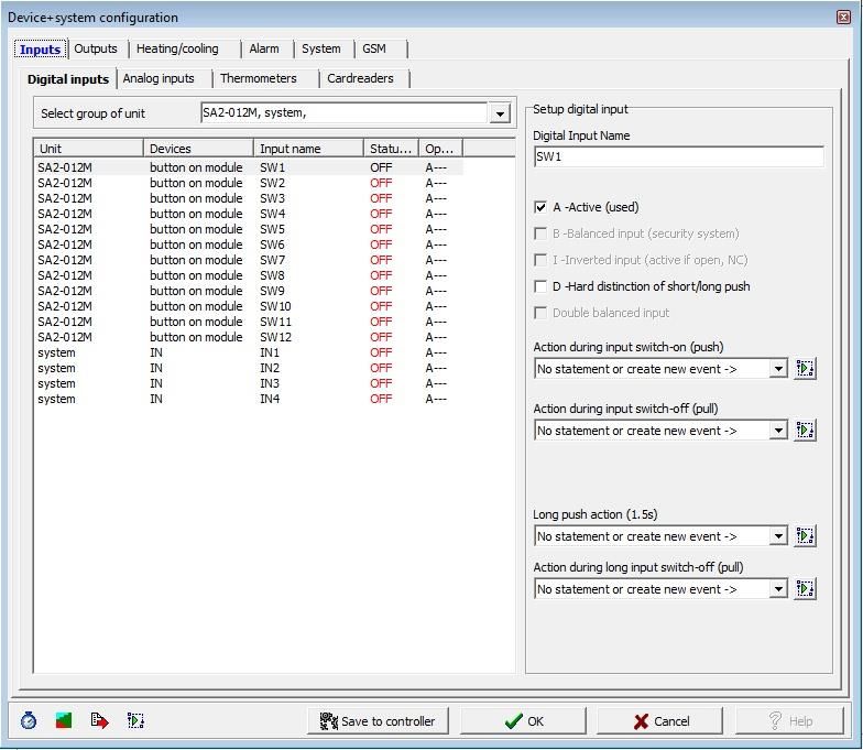
Installation manual Connection Server
1. Preface
Connection Server - It serves as a connection between iNELS BUS system units and other devices because it allows communication between devices with different
protocols. All devices can be then controlled through just one application. Besides the normal control of electronic installations, you can also control e.g. air condition,
home appliances.
The connection server uses a small but powerful computer, Raspberry PI B+, 3 with really low power consumption and the Linnux operating system.
In comparison with iMM Server, multimedia is not implemented here.
Protocols
RPC communication with application smartphones and tablets
Elkonet communication with central unit iNELS BUS
Miele communication with home appliances Miele
Camcontrol communication with IP cams
Artea communication with the Artea air handling unit
Coolmaster communication with gateway for air conditioning
Airpohoda communication with the Airpohoda air handling
eLAN-RF communication with wireless components of iNELS RF Control
Notes
Commands are given in purple (e.g.: sudo reboot)
! Warnings are given in red (e.g.: Connection server it allows you to set up only one door intercom.)
i Tips and tricks are given in green (e.g.: In the list of devices, we can add and remove devices manually)
Important application configuration commands in Linux (insert into terminal)
ifconfig - finding IP address of station/server, similar to ipconfig in Windows
mount - command for connection of certain device (CDROM, network drive, flash disk, etc.)
umount - command for disconnection of certain device
man - command man displays help e.g. man mount
sudo shutdown -h now - command shut down device Connection server from terminal
sudo poweroff - command shut down device Connection server from terminal
sudo reboot - command reboot device Connection server from terminal
2.7.2019 / rev.: 6 02-4/ 2018 3 / 41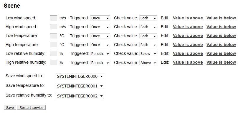
Installation manual Connection Server
2. Launching the connection server
a) Once you unpack the Connection server, let the device stabilize at room temperature.
b) Insert the micro SD card with the operating system into the slot. In newer CS revisions, the SD card is already inserted.
c) Connect the cabling (do not connect the supply yet):
Display HDMI device
LAN cable for Ethernet port
Keyboard to USB port
d) After connecting power supply (adapter with micro USB connector) the Connection Server will start automatically.
e) When starting the system you can watch the opening of individual services on the screen.
f) When services start up is completed, only one line, requiring the login name will appear on the screen
Login: imm
Password: imm123
! No characters are display when writing a password in terminal
g) To find the IP address after signup use the command ipconfig or extract it from the previous statement.
h) Further settings are performed via the IMM Control Centre web interface. A display device or keyboard need not be connected for the remaining time. Power supply,
micro SD card with system and application and connection to network LAN is sufficient to run Connection Server.
! Never insert or remove the micro SD card for running the Server Connection
2.7.2019 / rev.: 6 02-4/ 2018 4 / 41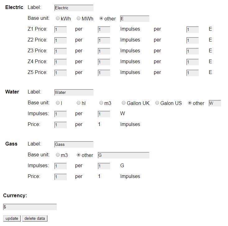
Installation manual Connection Server
iMM Control Center (hereinafter "iMM CC") is a web interface for adjusting the Connection Server.
iMM CC will run when you enter the address http://IPADRESA:8080 into your web browser and login using the access data.
Login data is by default the following settings: "admin", password "imm123"
If iMM CC does not run, connect to the server using the SSH protocol with the IP address of the Connection Server and enter it into the terminal
Command: sudo /etc/init.d/imm-web admin restart.
SSH authorization
Login: imm
Password: imm123
! You can change the Default password, in the terminal: passwd imm
i PuTTY is freeware that you can use to connect via SSH to the iMM CC web interface in Windows or Linux.
i Website will be automatic logout after 15 minutes of inactivity.
2.7.2019 / rev.: 6 02-4/ 2018 5 / 41
Installation manual Connection Server

In bookmark Server you can control the services, which are necessary for communication with a third party. With the software diagnostic is possible to check
each service status (button „Status“), to stop running (button „Stop“), or vice versa to start running (button „Start“).

i You can control all the virtual servers via Supervisor service link http://IPADRESA:9001

Function Display log:
To display the logs of the main server protocols, click on the individual names to display their listings in the next tab of the browser..

                                                                                                   Click to view the log listing

                                                                                                              Ability to restart the Logitech Media Server

                       2.7.2019 / rev.: 6                                           02-4/ 2018                                                                 6 / 41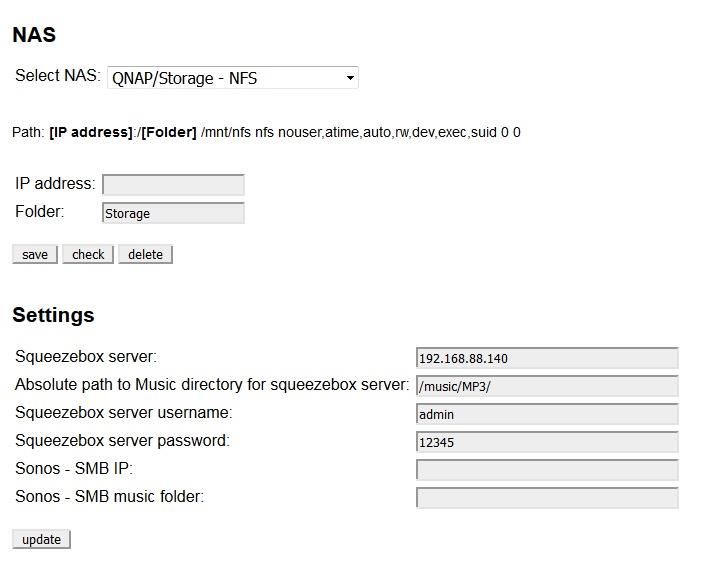
Installation manual Connection Server

    3.     Bookmark Configuration

The configuration tab is used to setup the primary Connection Server and is necessary for proper function..
Machine ID and Licence key are pre-set in factory default.

IP address input formats:
If the central unit is on a different computer network behind a router (NAT) and is not available directly, it can be connected to it over a selected open port on the router,
which is connected to the communications port CU (CU2 port 61682, CU3 port 9999).

           Version CU             Format                                                   Example:
           CU2                    [IPADDRESS]:[COMUNICATION_PORT]                          10.5.15.12:8454
           CU3                    [IPADDRESS]:[HTTP_PORT]:[COMUNICATION_PORT]              10.5.15.12:8080:4562

           Communication port - Elkonet for iMM server, Connection server, App iHC (CU2 port 61682, CU3 port 9999).
           HTTP port              - is the web server on CU3 where the created export.imm file is usually stored in the location
                                   http://IPADRESA/immfiles/export.imm (port 80)
           ASCII port             - port for communication with CU3 with a three-way third-party protocol (Telnet), which must first be set in IDM (optional), is set, the
                                  port for ASCII communication is 1111.
           Password               - password to access the central controller of the program is set in the IDM (optional)

Example setup menu settings:

                     Enter the IP address
                     of the central unit              Enter the specified
                                                      password for IDM

                                                                  Enter the communication port for ASCII

                                                                Enter the IP address of the Connection Server

                                                                                        Key ID

                                                                                       Licence Key

                                       Display the current status of CU

               Save, update

               Load export CU3               Delete export
               iNELS III

                        2.7.2019 / rev.: 6                                          02-4/ 2018                                                                           7 / 41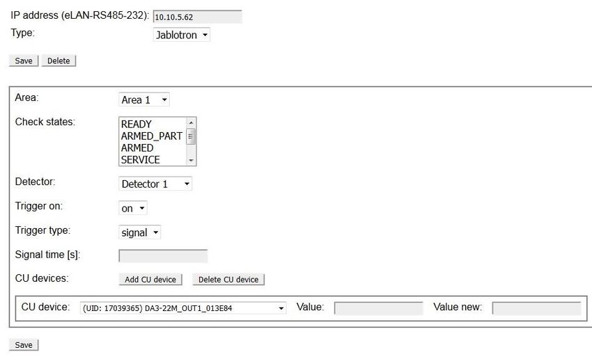
Installation manual Connection Server

This menu is used for the upload export.pub file from the IDM program to the Connection server and to manually edit elements in web browser.

! Function for upload export.pub is only for iNELS2 central unit.
! The central unit iNELS3 will download export automatically when you press the Load iNELS3 export button.
i In list we can add and remove elements manually.

                       2.7.2019 / rev.: 6                                     02-4/ 2018                                                       8 / 41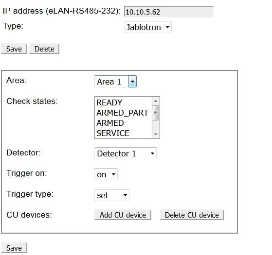
Installation manual Connection Server

       4.     Bookmark System

  In the System tab, you can reset the network settings, or restart or completely shut down using the "Shutdown" Connection server button.

  In the Network settings menu, you can set the IP address of the Connection Server. The options are to assign an address from the DHCP server or manually set the static
  IP address.
  We recommend that you set a static IP address so that it does not change if the DHCP server is reset

                                                          Set IP address            Set network mask         Set gateway router        Set DNS server
DHCP address

Static IP address

                                          Save settings

  ! By setting the static IP address, the DHCP server will deactivate the IP address assignment and the IP address will be set according to the user settings. Network IP
  address information.
  i If you are using a dynamic IP address from the DHCP server set the router to always allocate the same IP addresses based on the MAC addresses.

  In the Data and time settings menu - displays the system time to check and adjust the time.

                          Refresh settings                                         Save settings

  In the Change Password menu - change the password.

  In the Edit password menu (remote control - setting and editing the heating plans in the application.

                         2.7.2019 / rev.: 6                                         02-4/ 2018                                                                              9 / 41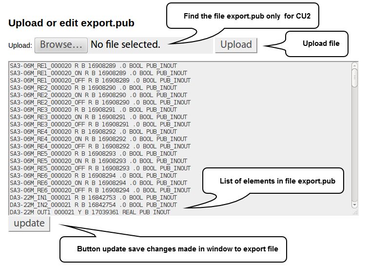
Installation manual Connection Server

Other settings in the menu:

 Button Shutdown you can remotely shutdown
 Connection server from Web interface.
                                                 ! To re-start, disconnect and reconnect the micro USB power
                                                 connector to the Connection Server.

 Button Restart you can remotely restart
 Connection server from a Web interface.

 Set the scheduled reboot of the
 ServerConnection at a specified time of the
 week.                                                                                Delete settings

     Set the minute, hour and day of the week
                                                                              Save settings
 Button Update refresh NFS sharing settings in
 the file /etc/fstab

                    2.7.2019 / rev.: 6               02-4/ 2018                                                10 / 41
Installation manual Connection Server
5. Bookmark Media
The tab is only available for RPI from version 3. The Settings section is taken from iMM. The NAS section is used to enter the IP address for the NAS. When selecting the
manual option, a user option is inserted instead of the IP address e.g.:
MANUAL_SYNOLOGY_NFS:
IP_ADDRESS/volume1/Storage /mnt/nfs nfs nouser,atime,auto,rw,dev,exec,suid 0 0
MANUAL_QNAP:
IP_ADDRESS/Storage /mnt/nfs nfs nouser,atime,auto,rw,dev,exec,suid 0 0
MANUAL_QNAP_SMBCIFS:
IP_ADDRESS/Storage /mnt/smb cifs username=,password=,nofail,x-systemd.automount,x-systemd.requires=network-online.target,x-systemd.device-timeout=1 0
MANUAL_NFS:
IP_ADDRESS/Storage /mnt/nfs add parameters
MANUAL_SMB:
IP_ADDRESS/Storage /mnt/smb add parameters
LMS is available on port 9000, as well as in iMM.
Select the type of sharing with
NAS
Set up a path to music files
2.7.2019 / rev.: 6 02-4/ 2018 11 / 41Installation manual Connection Server
6. Bookmark HA-BUS
Bookmark HA-BUS can be used for interconnection of iNELS3 BUS and a decentralized control system KNX/EIB, which allows control from the iHC app.
You can add more INELS3 central units in this folder.
i In the last hardware revision of Raspberry Pi 3 it is possible to add up to 8 INELS3 central units
Requirements for interconnection with KNX / EIB:
KNX Router
Export group addresses from the program ETS3 – 5
In iNELS3, enter the IP address of the iNELS3 central unit, the password (optional) and a note; adding is completed with the Add button.
Once added, the export is downloaded automatically from the central controller and the prefix "inels3" is added. The last character of the prefix (A-H) specifies the
insertion order for the resolution between the central units.
IP address of the CU3 central
unit
Enter the communication port
Name – configuation in IDM
Name of CU3 added
Displays the current status
of the set CU3
Adds the configured CU3
User note
Example of Prefix IP address CU
Priefix inels3A
Reset the export of the Remove CU from the list
selected CU
For KNX / EIB, the KNX the Gateway must also be filled in. Where you can enter the IP address of the gateway KNX router and save by using the Save button. Then, select
the group address export file (see KNX export group address) and export.
The Export group addresses are done in accordance with the ETS format: 1/1 (Name / Add.) Separate each of them by using semicolons.
Before inserting the export it need to be more adapted behind the semicolon refill data type according element values (True, False, 0-255, 0-100) see. KNX DPT link.
Is used to set pairs of KNX device and CU3 device, which will synchronize with each other.
KNX element selection
Selecting an element
from the central unit
List of created pairs
2.7.2019 / rev.: 6 02-4/ 2018 12 / 41Installation manual Connection Server
Example export group addresses from ETS:
Example of data in a supplemented file Test_group.cvs:
"Group name";"Address"
Dimming;0/-/-
New Middle Group;0/0/-
Dim A;0/0/1;5
Dim B;0/0/2;5
Switching;1/-/-
New Middle Group;1/0/-
D;1/0/0;1
switch A;1/0/1;1
switch BCD;1/0/2;1
Shutters;2/-/-
New Middle Group;2/0/-
Shutters1;2/0/1
Shutters2;2/0/2
Sensors;3/-/-
New Middle Group;3/0/-
Temperature;3/0/0;9
A switch in example; 1/0/1; 1 has value as shown in Table 1 behind a semicolon (True, False) means that a switch.
Data type Data Type Value
1 1 bit bool True | False
5 8 bit num 0-255
5.001 8 bit num 0-100
6 8 bit num -128 +127
232 3 byte num RGB [0,0,0] - [255,255,255]
On the Configurations tab, make sure the export listing contains the KNX elements. If so, in the Rooms tab, paste the KNX elements into the selected room. Put the KNX
elements into the room in the same way as the iNELS3 elements, the KNX devices have a knx_ prefix.
! This manual describes the interconnection of iNELS3 and KNX systems, not the KNX element settings.
! If the central unit does not have a password set, leave the insertion field blank.
i Names of elements in the room without the prefix will be converted automatically.
2.7.2019 / rev.: 6 02-4/ 2018 13 / 41Installation manual Connection Server
7. Bookmark RF Configuration
For communication between wireless RF devices and the Connection server an eLAN-RF-003 or eLAN-RF-Wi-003 smart box is required.
Enter the eLAN-RF IP address.
! RF elements are assigned to eLAN-RF via the iHC-MAIRF application or via the eLAN-RF web interface (see the iHC-MAIRF manual)
For authorization purposes on eLAN-RF, input boxes are for username and password. Click the Apply changes button to reset the process and apply the changes.
IP address eLAN-RF or eLAN-
User name and password RF-Wi
eLAN-RF / eLAN-RF-Wi
Save Apply changes
i For control of RF elements enable in the iHC-MA, iHC-TA settings.
8. Bookmark Logging
RF logging for logging changes on RF eLAN. You can add more eLAN-RF or eLAN-RF-Wi.
After adding eLAN-RF, click Apply changes to show changes. After loading elements from eLAN-RF, you can select an element, name it and add it to the monitored
elements. Apply changes again. Data from the tracked item can be downloaded via Download or deleted via Clean.
CU3 logging for logging changes at CU3.
You can select an element, name it and add it to the elements you are watching. Apply changes. Data at the
tracked item can be downloaded via Download or deleted via Clean. All tracked items can be removed via
Remove all. The Download section also serves for downloading data. Wherein, the selected element is
referenced along with the time period.
2.7.2019 / rev.: 6 02-4/ 2018 14 / 41Installation manual Connection Server
9. Bookmark Zones
Bookmark Zones is used to configure the zones for the Connection server. With the possibility to add multiple zones.
To insert a fill zone name, IP address and choose a zone type change switch to yes.
Name of zone
IP address
zone
Select the zone
type
Create a set
zone
Viewing created
zones
Remove zone
! Connection Server only allows the insertion of GIOM 3000 weather station.
! If you set your password in the GIOM administration, be sure to check Except - status.xml
2.7.2019 / rev.: 6 02-4/ 2018 15 / 41Installation manual Connection Server
10. EventScript
In bookmark EventScript creates events, based on which, the pre-set start script. The event is performed if the element reaches the set value of the event. You can use
different kinds of elements relay, DAC. Etc.
In menu Triger Rules you can create events, based on which the script runs.
You can select a CU for which you can set a rule. If you enter the IP address of the CU, the Configuration tab is displayed by default. If you enter the CU addresses in the
HA Bus tab, you will be able to select a particular CU, ie inels3A, inels3B, inels3C, etc.
Enter a unique key in the format: 0x00000000
The value for running the script
Absolute path to script
Add create event
! EventScript uses ASCII protocol, which must be turned on in IDM program, into a free port and in bookmark Configuration in iMM CC insert ASCII port for
communication.
Depending on the setting ASCI protocol set value in hex or DEC example. 50 in (HEX) is 80 (DEC).
EventScript run with all device modes (HEX, HEX with prefix and DECIMAL)
Tracking Element Value in Script:
To see the value of the element, insert "?" in the Value field, and then read it through the sys.argv [0] system with argument 0. The script will run periodically after 5
seconds, and the script will respond to the changing value of the variable.
Reading the value of the element in the script:
To read the value of the element, insert "?" in the Value field, and then read it through the system sys.argv [0] with argument 0. The script will run periodically after 10
seconds and dynamically respond to changes in the element's value based on logic in the script. This function can be used, for example, to start the heat recovery
depending on the temperature of the sensor.
2.7.2019 / rev.: 6 02-4/ 2018 16 / 41Installation manual Connection Server
When setting the air conditioner trigger, the event is triggered when the element state changes from 0 to 1.
Air conditioning list
CU device (Only system int / bit)
Features available for specific air
conditioner
Save the Trigger Restart service
List of defined triggers
AC Trigger Rules used to pair the CU element and AC function. This way you can store AC states to CU and control AC from CU.
AC: selects the assigned unit.
CU device: select the element you want to assign to that AC function.
Function: select the air conditioning function.
Description of AC Features:
• power (rw) - 0 and 1 can be used to monitor whether AC is on, with AC enabled (outside Area - 0-100 range)
• on / off (t) - turns on / off when changing from 0 to 1
• set_temp (rw) - to monitor the desired temperature in AC with the option to set the temperature
• increase / decrease_temp (t) - change from 0 to 1 to increase / decrease the temperature by 1 ° C
• cur_temp (r) - to monitor the current temperature in AC
• mode (rw) - to monitor the current mode in AC with the option to set the mode
• control mode (rw) – to monitor the current control mode with the option to set it
• ventilation_with_timeout (w) - set the ventilation for the desired time (in minutes), after the set time elapses, the AC returns to its original state
• heating season (rw) – to monitor whether the heating season is set up
Feature Types:
• (r) - AC reading only and CU write
• (w) - only write status from CU to AC
• (rw) - bidirectional write (combination (r) and (w))
• (t) - a trigger that composes to execute specific functions (activation is performed when the CU element state changes from 0 to 1)
Note: AC write is only done when the CU element state changes.
2.7.2019 / rev.: 6 02-4/ 2018 17 / 41Installation manual Connection Server
Control and read AC status via CU
Working with mode / fan speed works with tables below that match the numeric value and mode / fan speed
Mode:
Value Mode
0 unsupported
1 unknown
2 off
3 auto
4 heating
5 cooling
6 ventilation
7 dry
8 periodic_ventilation
9 periodic
10 night_precooling
11 balancing
12 overpressure
13 service
Supported Modes for Individual AC:
AC Mode
LG auto, heating, cooling, ventilation, dry
CoolMaster auto, heating, cooling, ventilation, dry
Atrea off, auto, ventilation, periodic_ventilation, periodic, night_precooling, balancing, overpressure
Intesis auto, heating, cooling, ventilation, dry
Nilan off, auto, heating, cooling, service
AirPohoda unsupported
Universal off, heating, cooling
Fan speed:
Value Fan speed
0 unsupported
1 unknown
2 off
3 auto
4 level_1
5 level_2
6 level_3
7 level_4
8 level_5
9 level_6
10 level_7
11 level_8
12 level_9
2.7.2019 / rev.: 6 02-4/ 2018 18 / 41Installation manual Connection Server
Supported speeds for each AC:
AC Fan speed
LG auto, level_1, level_2, level_3
CoolMaster auto, level_1, level_2, level_3, level_4
Atrea unsupported
Intesis auto, level_1, level_2, level_3, level_4, level_5, level_6, level_7, level_8, level_9
Nilan off, level_1, level_2, level_3, level_4
AirPohoda unsupported
Universal unsupported
Set / Cur temp:
For temperatures, a multiple is used to maintain accuracy 100:
temp * 100 = 21,50 * 100 = 2150
Control mode:
Value Control mode
0 unsupported
1 unknown
2 manual
3 auto
4 temporary
Supported control modes for each AC:
AC Control mode
LG unsupported
CoolMaster unsupported
Atrea manual, auto, temporary
Intesis unsupported
Nilan unsupported
AirPohoda unsupported
Universal unsupported
2.7.2019 / rev.: 6 02-4/ 2018 19 / 41Installation manual Connection Server
11. Bookmark A/C
Used to define the air-conditioning or heat recovery by third parties and their control through the iHC application.
Supported are:
LG Clims
Coolmaster, CoolMasterNet
Air Pohoda
Atrea
Universal 0-10V
LG Clims via PI-485 eLAN-RS485/232 or Advantech Adam 4571
CoolMaster series 1000D, 2000S, 3000T, 4000M, 6000L, 7000F, 8000HM, 9000M, CoolMasterNet over Advantech Adam 4571
CoolMasterNet
Daikin (DK) Mitsubishi Electric (ME)
Fujitsu (FJ) Mitsubishi Heavy (MH)
Gree (GR) Panasonic(PN)
Hitachi (HT) Samsung (SM)
Intensity (MD) Sanyo (SA)
Kentatsu (KT) Toshiba(TO)
LG (LG) Trane (TR)
Midea (MD) Compatibility: indoor, outdoor units.
Others:
Atrea Duplex 180 EC4 P (0-10), Duplex 180 EC4 P (0-100)
AiRPohoda by Adam 4571
2.7.2019 / rev.: 6 02-4/ 2018 20 / 41Installation manual Connection Server
Universal 0-10V by DAC 0-10V
ADAM-4570_4571
RS-232 Pin order
Pin. No. Description
Pin 1 DCD
Pin 2 Rx
Pin 3 Tx
Pin 4 DTR
Pin 5 GND
Pin 6 DSR
Pin 7 RTS
Pin 8 CTS
Pin 9 RI
RJ-48 Pin order - RS-422
Pin. No. Description
1 Tx -
4 Tx +
5 GND
7 Rx +
9 Rx -
RJ-48 Pin order - RS-485
Pin. No. Description
1 Data -
4 Data +
5 GND
It is used to define air conditioning and control it through the iHC application. Supported communication card for LG air conditioner is PI485. The air conditioner must be
connected via an eLAN-RS485/232 or Advantech Adam 4571.
Set IP address and port
2.7.2019 / rev.: 6 02-4/ 2018 21 / 41Installation manual Connection Server
Is used to define air conditioning via the Coolmaster universal control unit and control it through the iHC application.
First step:
First, set the Coolmaster control unit according to the manufacturers manual. (Usually via DIP switches inside the unit) Setup converter LAN-serial485 (Recommended
converter: Adam 4571) according to the Coolmaster manual and connect the converter to the CoolMaster control unit.
Test communication:
If the air conditioner control unit is properly connected to the Coolmaster the display alternatively displays the temperature and mode.
Second step:
Moving on to set the air conditioner in the web interface http://localhost:8080/clims and fill name and IP address of the convertor and press the Save button, the settings
wait for UID to load the air conditioning in system. Now you can select the number of units and save the CoolMaster unit.
! If unsuccessful use the reload button and check the air conditioning loaded UID communication converter with the Coolmaster according to the manual
For older Coolmasters version is necessary to set convertor to appropriate port:
Coolmastr type: 1000D, 2000S, 3000T, 4000M, 6000L, 7000F, 8000I(HM), 9000M
Convertor: Adam 4571 nebo Gnome 485 Port: 10001
CoolMasterNet (default setup) Port: 10102
Perform the function check via utility ncat command format: ncat IPADRESA PORT
Example ncat in terminal:
Command Significance
Command ncat 10.10.10.111 10102 Connection to Cooler Master / Convertor
Answer > Returns the character command line
Command stat2 List states Air conditions
Answer 000 OFF 25C 27,80C High Heat OK 0 Return state Air condition
For windows you can use SPU (Serial port utility)
i Commands and pin setup for cable connection of air conditioning can be found in the reference manual for example: CoolMasterNet
! Maximal number of simultaneous connections for CoolMasterNet is 4, only 2 for the Adam 4571 convertor.
Used to define air recovery, called Air pohoda and control through the iHC application.
The recuperation must be connected via an eLAN-RS485/232 or Advantech Adam 4571.
2.7.2019 / rev.: 6 02-4/ 2018 22 / 41Installation manual Connection Server
Used to define air recovery called Atrea and control through the iHC application.
New Duplex EC RD5. Additionally, you can enter more Atrea units and enter the unit name.
Enter the name of the unit
Select unit type
Enter the IP address of the unit
Outside temperature source for
regulation
Internal temperature source for
regulation
Indoor Temperature Sources:
CP - The indoor air temperature is measured by a sensor built into the CP-Touch controller
The T-ETA - indoor air temperature is measured by a sensor built into the unit on the exhaust air outlet
TRKn - indoor air temperature is measured by sensor connected to RD5-K module (optional unit with RD5 control unit)
CU - indoor air temperature is supplied by the superior system (central unit)
Outdoor Temperature Sources:
HVAC - Internal sensor - The outdoor air temperature is measured by the unit's internal sensor
CU - outdoor air temperature is measured by superior system (central unit)
Used to define universal air conditioning using DAC 0-10 V and control through the iHC application.
Set maximum temperature climatization
2.7.2019 / rev.: 6 02-4/ 2018 23 / 41Installation manual Connection Server
Used to add Nilan ventilation units connected to the eLAN-RS485/232 via the RS485 interface
Connection server communicates with eLAN-RS485/232 using Ethernet.
IP address eLAN-RS485/232
Device Name
List of created devices in
eLAN-RS-485
Selection of input on the
Nilan unit to which the
current temperature sensor is
connected
It is used to control air conditioners supported by the Intesis box.
Name - Intesis unit name.
IP address – field for entering the IP address of the unit
2.7.2019 / rev.: 6 02-4/ 2018 24 / 41Installation manual Connection Server
12. Bookmark ESS
It is used to connect security systems (Jablotron, Paradox) with the eLAN-RS485/232 to iNELS.
It is possible to establish individual functions of the devices connected to the CU Central Unit when an alarm signal is sent from the individual detectors.
Security Settings for Jablotron:
Select the type of
Set the IP address of the connected device to
converter the converter
Select area monitoring (set by
security system)
Selecting a monitoring state
for a given area (using the
Ctrl button to select multiple
statuses at a time)
Selection of the
monitored detector
Selection of the monitored
state for which the
Function type selection: component overlay feature
set - change the state of the is to be performed in
device the Central Unit (CU)
signal - set the duration of
the signal
Set the value of the Selection of an
component when the component from the CU
central unit export Set the duration of Component set value after
alarm function is
the signal alarm time (alarm)
activated
Paradox Security Settings: It varies only with the number of areas and detectors (Area) and other states in the given area (Check states).
2.7.2019 / rev.: 6 02-4/ 2018 25 / 41Installation manual Connection Server
13. Bookmark Rooms
Bookmark Rooms is used to configuration of the rooms.cfg, for loading the iHC application (more information in the iHC manual).
Rooms are actually "virtual rooms" (groups), which have the option to group the icons and zones for one or more screens.
First enter the room name, save it with the Add button.
! Only A-Z, a-z, 0-9, -_, can be used for the room name.
Using the upload and download buttons, you can download or record the rooms.cfg (bookmark of the already created rooms).
Set name of
room
Set password
for room
Create Room
File
upload
Download
File
Saved room
Remove
selected room
Edit room Set the room Rename
password Room
Using the Edit command, the menu adds the desired devices (scenes, zones ...) to the room.
Select the row
Select Type and column
Select specific device
Insert name Switch Icon read only
Add device device yes/no
View saved Remove device
devices
Move Up or
Down device
Edit Device Name Changing
device views
an optional absolute path
to a script that ends with
.py or .sh
Save settings
2.7.2019 / rev.: 6 02-4/ 2018 26 / 41Installation manual Connection Server
! Device type - the selected icon filters the elements (for example, the Lamp type filters the elements on the dimmers, the scene displays the field for writing the absolute
path ...).
i By switching the Read only function to "yes", the icon will display only the status of the non-controllable element.
Adding a device:
Type Device Type, Name, Row / Column. In the Attributes field, select the device you want from the menu.
Add a scene:
Select a scene in the type. Enter the name, Row / Column. You can use the programmed script to control the scenes, which can trigger various functions defined in it. You
must keep an absolute path starting with "/" and ending with the "Python" script that you type in the Attributes field. Multiple elements can be added to the scene.
2.7.2019 / rev.: 6 02-4/ 2018 27 / 41Installation manual Connection Server
14. Bookmark Cameras
Bookmark Cameras is used for defining IP cameras, which you want monitor and control by the iHC application.
The HTTP and RTSP ports are only filled in if you have IP cameras configured to access the external network by redirecting ports to the router or using the ONVIF protocol.
- If you connect the camera remotely over the HTTP port, you get to its web interface and you can fully control the camera.
- If via RTSP, then you only get to the camera stream. For more information on setting these ports, see the manual of the selected camera.
If you do not enter the HTTP and RTSP ports they remain with the defaults of HTTP port 80, RTSP port 554.
Supported cameras: iNELS cam
AXIS protocol VAPIX2 cameras with firmware version number 4.0.X.X and VAPIX3 with firmware version 5.0.X.X
Camera with ONVIF protocol profile S certification ONVIF link
Cameras supporting RTSP stream
In the New camera menu, add IP cameras to the Connection server.
Example integration of cam Axis supported ONVIF: connect the camera according to camera manual and create a user for the ONVIF protocol which might be different
according to manufacturer. Set the video stream profile: MJPG to MJPEG/JPEG and the second RTSP stream to MPEG4/H264.
Set name for camera
Set IP address camera
Set user name
Password
Port for MJPG
Port for RTSP stream
Select an API
Camera manufacturer
Camara Type
The FW version from
which the camera
manufacturer
supports the onvif Date Certified
protocol
Create camera
i The service port is the ONVIF port usually set on port 80. If the camera is behind NAT it is necessary to redirect to the router and this port otherwise the camera cannot
be configured
Ports by default:
Axis - ONVIF HTTP port: iHC: 80 RTSP port - iMM: 554 Application support: iHC-MA, TA, Mi, Ti
Other ONVIF cameras HTTP port: iHC: 554 RTSP port - iMM: 554 Mobile stream support via RTSP: only in app. iHC-MA, TA!
In the Select stream menu, select the pre-set streams on the camera that is assigned to the iHC mobile app.
The List of cameras menu displays saved cameras on the Connection Server and allows you to edit or delete the selected camera from the web interface.
If you are creating an ONVIF camera, the next step will offer the stream to select, possibly editing it, or enter it manually. The manual selection will also be offered if the
streams are not successfully downloaded from the camera.
Reloads the profiles
from the camera
Reloads the profiles
from the camera
2.7.2019 / rev.: 6 02-4/ 2018 28 / 41Installation manual Connection Server
15. Bookmark Miele
In the menu Miele set the IP address of the Miele gateway device that serves to control remotely appliances over powerline, or ZigBee protocol.
Supported gateways: XGW 2000, XGW 3000 (Firmware 1.1,1.2)
! Set IP address MieleGateWay which is stored in the file /etc/imm/miele
i The GW restart relay is used to switch off / on if the gateway loses the network connection and sends the notification to the user's email.
2.7.2019 / rev.: 6 02-4/ 2018 29 / 41Installation manual Connection Server
16. Bookmark Intercoms
In the Intercoms tab, you can specify settings for door intercoms and VoIP accounts for iHC applications.
To create an account for LARA or Mobile, use the New intercom account section.
New contact name
SIP name
SIP password
Add a new contact Streaming video URL of the
device
To create a door phone account, use the New intercom account (for a door phone) section.
Choice of three types of door intercoms (2N, IP-Bold, Dahua).
Enter a URL to unlock the lock
Choice of sound type
For the correct function of calls using iHC applications, it is necessary to assign the highest priority to the PCMU codec in the intercom - 2N (Services / Telephone / Audio /
Codecs).
When making a door-to-door contact, it is not limited to one door, more can be entered.
New ability to create groups. Create individual contacts, add them to the group. Make a group call name, the call will be applied to all the contacts in the group, who will
receive the first call, who will communicate. Contacts are grouped into the group via the New intercom group, where all contacts are inserted and separated by commas:
LARA1, LARA2, LARA3.
You can set the maximum ringtone length in the Asterisk settings section.
Apply settings button activates newly created VoIP accounts and restarts the PBX Asterisk.
2.7.2019 / rev.: 6 02-4/ 2018 30 / 41Installation manual Connection Server
In the list of created contacts, which contact is registered on the SIP server is colour-coded.
! The connection server allows you to set up a single door intercom via DTMF on the web interface.
i Stream for cam add in format rtsp://IPADRESA.
i Manual link for video intercom the iHC application can be added in the contact intercom field with the IP address in this format:
http://IPADRESA/enu/camera640x480.jpg.
! The connection server allows only one door intercom to be opened on the web interface.
i In the case of multiple 2N IP intercoms, all must be set to open as well (User name, Password, Lock code).
2.7.2019 / rev.: 6 02-4/ 2018 31 / 41Installation manual Connection Server
17. Bookmark Energy
The Energy module allows recording of consumed energy for a day, week, month and year. Consumed energy is displayed in the iHC application not only in a given
quantity but also in financial value in the form of a table or graph.
The data is stored on the Connection Server even when the power is off or on.
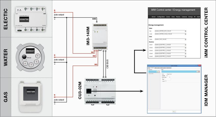
Energy is recounted based on the amount of impulses that the outputs from meters provide (gas-meters, electrometers, water-meters). Impulses are further processed in
an optional input unit of system iNELS (IM2-140M, IM2-20/40/80B) in form of a counter. This value is by means of export.pub transferred to Connection Server where
variable is in iMM CC on bookmark Energy assigned to Water/Gas/Electric.
The actual setup conversion of pulses per unit of measure, currency selection and adjustment of the currency / unit is done in the web interface in the Connection Server.
Connection of electric meter, gas meter or water meter
The connection of a particular meter is executed via the binary input unit. The polarity of the supported meter, i.e. + and - is distinguished. If necessary, observe the
polarity and connect the "-" terminal to the GND terminal and the "+" terminal to the IN terminal.
Settings in IDM2:
1. Click on the System Configuration button (icon of hammer and screwdriver – F11)
2. Select bookmark System -> counters
3. Add counter that you name by energy you want to measure
4. Create a new action that you name e.g. upload electricity
5. Add a command in the action which will be user action -> commands for counters -> increment counter
6. Select counter that corresponds with given action (e.g. for upload electricity you put counter electricity)
7. Add the action created as described above in system configuration to relevant binary input in action line when the input closes
8. Once the file export-pub is created and uploaded to iMM server, in bookmark Energy you can assign in the counter value line (electricity_VALUE). It must be VALUE in
the line.
2.7.2019 / rev.: 6 02-4/ 2018 32 / 41Installation manual Connection Server
Creation of counter in iDM2:
Create increment counter action:
2.7.2019 / rev.: 6 02-4/ 2018 33 / 41Installation manual Connection Server
Action assignment to binary input where output from measuring instrument is connected
Assign a counter value to the iMM Control Center
Example:
1 kWh = 100,- Kč = 100 pulse
Base Unit – kWh
Impulses – 100 per 1 kWh
Price – 1 per 1 impulse
To create a counter in IDM3, see Create counter IDM3
2.7.2019 / rev.: 6 02-4/ 2018 34 / 41Installation manual Connection Server
In the Energy Management menu, select binary inputs for WATER, GAS, and ELECTRICITY and allocate units and impulses to them.
custom name
Option to enter
your own unit
Base Unit
Number of units
For the Z2 meter, in pulse rate ratio
the price for the
specified number
of pulses The number of
pulses set for
loading units
custom name
Option to enter
Base Unit your own unit
custom name Option to enter
your own unit
Base Unit The number of
pulses set for
loading units
Price for 1 pulse
Choice of currency
Save settings Clear settings
To create a counter, see the Energy tab
2.7.2019 / rev.: 6 02-4/ 2018 35 / 41Installation manual Connection Server
Creating a counter in IDM3
Managers tab, select the System Manager and go to the tab Counters where you create a counter name. Click the + icon to fill in the name and "tick" the item
Apply to export.
Counter name
Creating a counter
Export
Creating functions for counter
In the Wires tab, select the Function Manager option. Here you create a function named Energy Increment (the function type is Counter).
Move the switch and central units to the desktop and double click on switch icon edit and select IN Digital input M3-80B.
In the Function tab, select ADD connections, make the connection by pulling the wire from the switch icon on the icon and select Central Unit Energy.
2.7.2019 / rev.: 6 02-4/ 2018 36 / 41Installation manual Connection Server
In the tab, Function select Wire Manager, select the input (IN) Energy through button the Edit function to adjust to Action: Short down User function: Energy Increment.
Add the created counter to iMMCC Energy management
Currency setting option. There is also the option to erase all measured data via the delete data button at the bottom of the page.
Select the required currency
2.7.2019 / rev.: 6 02-4/ 2018 37 / 41Installation manual Connection Server
18. Bookmark Giom
On Giom you can create scenes based on data from the Giom Weather Station.
You can choose whether the scene is called once or periodically (Triggered), and whether you want to check if exceeds or falls below the value (Check value).
Depending on the values set on the web interface, the scene is performed when the value is greater than or less than the scene setting value
Perform the scene Check values exceeding The selected command is executed
Low wind speed once or periodically / falling below when the value is exceeded
High wind speed
The selected command is
Low temperature executed when the value
falls below
High temperature
Low relative humidity
High relative humidity
It is used to write measured
values to CU (wind speed,
temperature, humidity)
Save settings
Restart to activate save
You can edit the scene in the Edit menu. In the selected scene, you can add or remove relay units.
Connect Giom station as a zone:
IMM connection with the server is defined in iMMControl Center in the "Zones" where it is necessary to state "Is it Giom?" switch from "no" to„yes“.
Settings are made via the web interface. The first time finding of the IP address of the weather station is possible with the software "Mlocator", which can be downloaded
from the manufacturer's website.
! For proper function you must first set up Giom as a zone. If you set your password in the GIOM administration, be sure to check Except - status.xml.
i Information from weather station can be displayed in the iHC applications or iMM application by pressing the left button on the clock icon at the top right of the
application.
2.7.2019 / rev.: 6 02-4/ 2018 38 / 41Installation manual Connection Server
19. Bookmark Manual
In bookmark Download you can download the current version manual in PDF format.
20. Bookmark Default settings
Bookmark Default settings is used for reset settings to default state.
Reset all server settings to default - factory settings (all user settings are deleted).
Reset all devices dependencies to default - deletes only user settings and their dependence on other iMM server features.
21. Bookmark Audit
Bookmark Audit is used to show and download LOG file option events for diagnostic developer purposes.
22. Bookmark Logout
Logout from the web interface.
2.7.2019 / rev.: 6 02-4/ 2018 39 / 41Installation manual Connection Server
23. Appendix
Control 4
Link Control 4 with iNELS wiring using the Connection Server
Requirements for linking Control 4: iNELS3 central unit
Controller HC-250, HC-350, HC-800, EA-3
Composer software (2.7.2, 2.8.1, 2.8.2 and higher)
iMM Server or Connection Server 3.219 or higher
Setting up in the licensed Composer program first step is to store iNELS drivers:
iNELS3_Master_Driver.c4i - The main link driver between and Connection Server to C4
iNELS3_Switch.c4i - Switching units SA3
iNELS3_Dimmer.c4i - Dimmers DA3, DAC3
iNELS3_PIR.c4i - PIR sensing disturbance monitoring on IM3 input
iNELS3_RGB.c4i - RGB control using RFDA-73M / RGB
iNELS3_Therm.c4i - Temperature sensor
iNELS3_Thermostat.c4i - Thermostat built in iDM (heating, cooling)
iNELS3_Blinds.c4i - Unauthorized driver in preparation for JA3 / 20B / DC, SA3
Copy these files to C: \ Users \ user \ Documents \ Control4 \ Drivers and run Composer for.
We will connect to the IP address of the C4 (Director), and then insert it into the project
iNELS3_Master_Driver, to which we set the IP address of the Connection Server.
Adding the iNELS3 Driver to the project
Procedure: Switch to the System design menu and continue to the Items window where you search for "iNELS" on the Search tab and then double-click the selected driver
into the project.
! First add the iNELS3 Master Driver before inserting the other iNELS3 drivers
Inserting an IP address into the Master Driver
Procedure: Go to the Connections menu where you select iNELS3 Master Driver and continue to the Network tab to open the iNELS 3 Master Driver and enter the IP
address.
2.7.2019 / rev.: 6 02-4/ 2018 40 / 41Installation manual Connection Server
Example of inserting the dimmer into the iNELS3_Dimmer controller
First, select the drive from the listing in iMMCC on the Configuration tab afterwards
DA3-22M_OUT1_000021 Y B 17039361 REAL PUB_INOUT
We will add iNELS3_Dimmer to the name and insert the address of the Device Address: 17039361.
Debug mode is an optional parameter, if we set Print and Log, we can validate it in the Lua Status tab.
! After completing the settings in Composer, restart the C4 directory.
• Note: The thermostat can modify the modes (attenuation, minimum, normal, comfort) based only on the next time stamp. The direct temperature setting function in
the application is not yet supported.
2.7.2019 / rev.: 6 02-4/ 2018 41 / 41You can also read