1U Slide Rackmount Rail Installation Guide - Network Appliance Platform - Version: 1.0 - Lanner Electronics
←
→
Page content transcription
If your browser does not render page correctly, please read the page content below
Network Appliance Platform

1U Slide Rackmount Rail
Installation Guide

                                 Version: 1.0
                  Date of Release:2022-01-04
1U Slide Rail Installation Guide

This manual describes the overview of the various functionalities of this product, and the information you
need to get it ready for operation. It is intended for those who are:
- responsible for installing, administering and troubleshooting this system or Information Technology
   professionals.
- assumed to be qualified in the servicing of computer equipment, such as professional system
   integrators, or service personnel and technicians.

The latest version of this document can be found on Lanner’s official website, available either through the
product page or through the Lanner Download Center page with a login account and password.

This document utilizes different icons in order to make selected text more transparent and explicable to
users.
              Icon                                                 Usage

                                      This mark indicates that there is something you should pay special
          Note or Information         attention to while using the product.

                                      This mark indicates that there is a caution or warning and it is
         Warning or Important         something that could damage your property or product.

To obtain additional documentation resources and software updates for your system, please visit the
Lanner Download Center. For troubleshooting the issues with your system, please check the Lanner Q&A
page for a diagnostic procedure and troubleshooting steps.

In addition to contacting your distributor or sales representative, you could submit a request to our Lanner
Technical Support page to fill in a support ticket to our technical support department.

Your feedback is valuable to us, as it will help us continue to provide you with more accurate and relevant
documentation. To provide any feedback, comments or to report an error, please email to
contact@lannerinc.com. Thank you for your time.

This document is copyrighted © 2020 by Lanner Electronics Inc. All rights are reserved. The original
manufacturer reserves the right to make improvements to the products described in this manual at any time
without notice.

No part of this manual may be reproduced, copied, translated or transmitted in any form or by any means
without the prior written permission of the original manufacturer.
Information provided in this manual is intended to be accurate and reliable. However, the original
manufacturer assumes no responsibility for its use, nor for any infringements upon the rights of third parties
that may result from such use.

                                                      2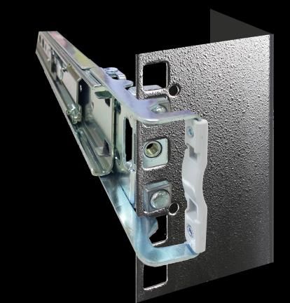
1U Slide Rail Installation Guide

All other product names or trademarks are properties of their respective owners.

Follow these guidelines to ensure general safety:
   Keep the chassis area clear and dust-free during and after installation.
   Do not wear loose clothing or jewelry that could get caught in the chassis. Fasten your tie or scarf and
   roll up your sleeves.
   Wear safety glasses if you are working under any conditions that might be hazardous to your eyes.
   Do not perform any action that creates a potential hazard to people or makes the equipment unsafe.
   Disconnect all power by turning off the power and unplugging the power cord before installing or
   removing a chassis or working near power supplies
   Do not work alone if potentially hazardous conditions exist.
   Never assume that power is disconnected from a circuit; always check the circuit.

Suivez ces consignes pour assurer la sécurité générale :
   Laissez la zone du châssis propre et sans poussière pendant et après l’installation.
   Ne portez pas de vêtements amples ou de bijoux qui pourraient être pris dans le châssis. Attachez votre
   cravate ou écharpe et remontez vos manches.
   Portez des lunettes de sécurité pour protéger vos yeux.
   N’effectuez aucune action qui pourrait créer un danger pour d’autres ou rendre l’équipement dangereux.
   Coupez complètement l’alimentation en éteignant l’alimentation et en débranchant le cordon
   d’alimentation avant d’installer ou de retirer un châssis ou de travailler à proximité de sources
   d’alimentation.
   Ne travaillez pas seul si des conditions dangereuses sont présentes.
   Ne considérez jamais que l’alimentation est coupée d’un circuit, vérifiez toujours le circuit. Cet appareil
   génère, utilise et émet une énergie radiofréquence et, s’il n’est pas installé et utilisé conformément aux
   instructions des fournisseurs de composants sans fil, il risque de provoquer des interférences dans les
   communications radio.

   Electrical equipment generates heat. Ambient air temperature may not be adequate to cool equipment
   to acceptable operating temperatures without adequate circulation. Be sure that the room in which you
   choose to operate your system has adequate air circulation.
   Ensure that the chassis cover is secure. The chassis design allows cooling air to circulate effectively. An
   open chassis permits air leaks, which may interrupt and redirect the flow of cooling air from internal
   components.
   Electrostatic discharge (ESD) can damage equipment and impair electrical circuitry. ESD damage occurs
   when electronic components are improperly handled and can result in complete or intermittent failures.
   Be sure to follow ESD-prevention procedures when removing and replacing components to avoid these
   problems.
   Wear an ESD-preventive wrist strap, ensuring that it makes good skin contact. If no wrist strap is available,
   ground yourself by touching the metal part of the chassis.
   Periodically check the resistance value of the antistatic strap, which should be between 1 and 10
   megohms (Mohms).

                                                       3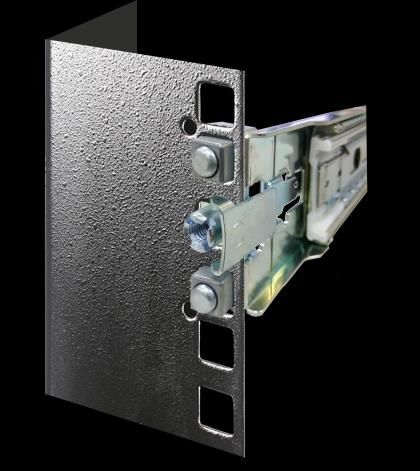
1U Slide Rail Installation Guide

   L’équipement électrique génère de la chaleur. La température ambiante peut ne pas être adéquate pour
   refroidir l’équipement à une température de fonctionnement acceptable sans circulation adaptée.
   Vérifiez que votre site propose une circulation d’air adéquate.
   Vérifiez que le couvercle du châssis est bien fixé. La conception du châssis permet à l’air de
   refroidissement de bien circuler. Un châssis ouvert laisse l’air s’échapper, ce qui peut interrompre et
   rediriger le flux d’air frais destiné aux composants internes.
   Les décharges électrostatiques (ESD) peuvent endommager l’équipement et gêner les circuits électriques.
   Des dégâts d’ESD surviennent lorsque des composants électroniques sont mal manipulés et peuvent
   causer des pannes totales ou intermittentes. Suivez les procédures de prévention d’ESD lors du retrait et
   du remplacement de composants.
   Portez un bracelet anti-ESD et veillez à ce qu’il soit bien au contact de la peau. Si aucun bracelet n’est
   disponible, reliez votre corps à la terre en touchant la partie métallique du châssis.
   Vérifiez régulièrement la valeur de résistance du bracelet antistatique, qui doit être comprise entre 1 et
   10 mégohms (Mohms).

Mounting Installation Precautions
The following should be put into consideration for rack-mount or similar mounting installations:
   Do not install and/or operate this unit in any place that flammable objects are stored or used in.
   The installation of this product must be performed by trained specialists; otherwise, a non-specialist
   might create the risk of the system’s falling to the ground or other damages.
   Lanner Electronics Inc. shall not be held liable for any losses resulting from insufficient strength for
   supporting the system or use of inappropriate installation components.
   Elevated Operating Ambient - If installed in a closed or multi-unit rack assembly, the operating ambient
   temperature of the rack environment may be greater than room ambient. Therefore, consideration
   should be given to installing the equipment in an environment compatible with the maximum ambient
   temperature (Tma) specified by the manufacturer.
   Reduced Air Flow - Installation of the equipment in a rack should be such that the amount of airflow
   required for safe operation of the equipment is not compromised.
   Mechanical Loading - Mounting of the equipment in the rack should be such that a hazardous
   condition is not achieved due to uneven mechanical loading.
   Circuit Overloading - Consideration should be given to the connection of the equipment to the supply
   circuit and the effect that overloading of the circuits might have on overcurrent protection and supply
   wiring. Appropriate consideration of equipment nameplate ratings should be used when addressing
   this concern.
   Reliable Grounding - Reliable grounding of rack mounted equipment should be maintained. Particular
   attention should be given to supply connections other than direct connections to the branch circuit
   (e.g. use of power strips).

Installation & Operation
   This equipment must be grounded. The power cord for product should be connected to a socket-outlet
   with earthing connection.
   Cet équipement doit être mis à la terre. La fiche d'alimentation doit être connectée à une prise de terre
   correctement câblée
   Suitable for installation in Information Technology Rooms in accordance with Article 645 of the National
   Electrical Code and NFPA 75.
   Peut être installé dans des salles de matériel de traitement de l'information conformément à l'article 645
   du National Electrical Code et à la NFPA 75.
   The machine can only be used in a restricted access location and must be installed by a skilled person.
   Les matériels sont destinés à être installés dans des EMPLACEMENTS À ACCÈS RESTREINT.

                                                     4
1U Slide Rail Installation Guide

Warning
Class I Equipment. This equipment must be earthed. The power plug must be connected to a properly wired
earth ground socket outlet. An improperly wired socket outlet could place hazardous voltages on accessible
metal parts.
“Product shall be used with Class 1 laser device modules.”
Avertissement
Équipement de classe I. Ce matériel doit être relié à la terre. La fiche d’alimentation doit être raccordée à
une prise de terre correctement câblée. Une prise de courant mal câblée pourrait induire des tensions
dangereuses sur des parties métalliques accessibles.
“Le produit doit être utilisé avec des modules de dispositifs laser de classe 1.”

Before turning on the device, ground the grounding cable of the equipment. Proper grounding (grounding) is very
important to protect the equipment against the harmful effects of external noise and to reduce the risk of
electrocution in the event of a lightning strike. To uninstall the equipment, disconnect the ground wire after turning
off the power. A ground wire (green-and-yellow) is required and the part connecting the conductor must be greater
than 4 mm2 or 10 AWG.

   Avant d’allumer l’appareil, reliez le câble de mise à la terre de l’équipement à la terre.
   Une bonne mise à la terre (connexion à la terre) est très importante pour protéger l’équipement contre les effets
   néfastes du bruit externe et réduire les risques d’électrocution en cas de foudre.
   Pour désinstaller l’équipement, débranchez le câble de mise à la terre après avoir éteint l’appareil.
   Un câble de mise à la terre est requis et la zone reliant les sections du conducteur doit faire plus de 4 mm2 ou 10
   AWG.

    Connect the grounding cable to the ground.
    The protection device for the DC power source must provide 30 A current.
    This protection device must be connected to the power source before DC power.

   Branchez le câble de mise à la terre à la terre.
   L’appareil de protection pour la source d’alimentation CC doit fournir 30 A de courant.
   Cet appareil de protection doit être branché à la source d’alimentation avant
   l’alimentation CC.

                                                           5
1U Slide Rail Installation Guide

  Package Content ........................................................................................................................... 7

                                                                      6
1U Slide Rail Installation Guide

Lanner provides a variety of rack mounting options for our appliances. The rack mount kit is included with
some systems, or may be purchased as an accessory for existing systems.

Applied Models:
All Lanner 1U Appliance Models

The mounting kit contains the following items:
   1x pack of Screws (for securing the rail brackets on the system)
   2x Slide Rails

Ensure that you have the following tools available:
   1x Screwdriver, number 2

                                                      7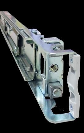
1U Slide Rail Installation Guide
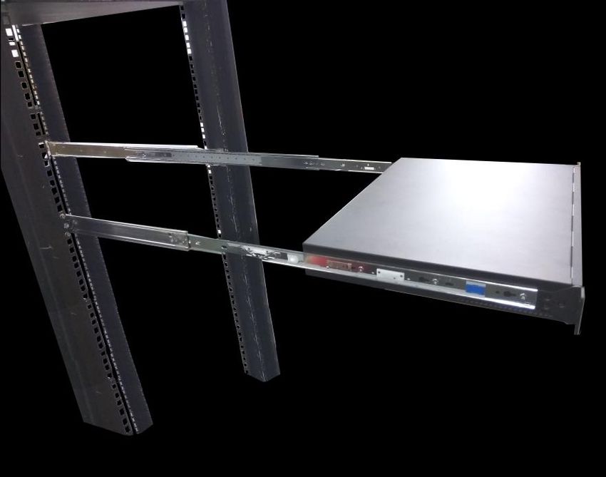
You can mount the network appliance on four posts in a 19-in rack or cabinet by using the rail mount kit.
1. Installing the device in a rack requires two people: one person lifts the device while the other secures
it to the rack.
2. If you are installing multiple devices in one rack, install the lowest one first and proceed upward in the
rack.
Slide Rail Part Explanation:
Bracket Inner Channel Outer Channel
1. Unpack a slide rail and slide the Inner Channel Outer Channel
inner channel all the way to its end.
2. Slide the bracket out to its end. Bracket
3. Locate and push the Release Tab on
Release Tab
the bracket to detach the bracket
from the Inner Channel, and
carefully slide it out.
8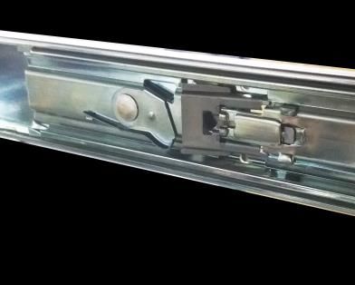
1U Slide Rail Installation Guide

 4. Align the bracket on the side of the
    system and make sure the screw-
    holes are matched. Then secure the
                                            Front                                   Rear
    bracket onto the system with three      F             r               o     n      t
    (3) screws.                             F             r               o     n      t

 5. Repeat Steps 1~5 to attach the
                                                                      Rear
    bracket to the other side of the
    chassis.

                                                                       Front

 1. The slide rails do NOT require
   screws. Simply latch on the three (3)
   available screw holes on the rack
   post front and lock it by clipping the
   rail’s Outer Channel front end to the
                                                              Use this clamp
   post as shown in the image. You                            to fix the rail
   should hear a “click” sound once it is                     front onto the          Click
                                                              post.
   firmly attached.
                                             Front Post

                                                    9
1U Slide Rail Installation Guide

 1. For the rear rack installation, latch
    and engage the bolts on the rail’s
    Outer Channel end with the two (2)
    available holes on the rack post,
    and the slide rail assembly will click                                                   Click

    into place.

 2. Repeat Step 1~2 to install the other
                                                  Rear Post
    rail onto the rack post.

 1. Stretch both of the Inner Channel of
 the rail out to their fullest extent. You
 will hear a click sound when they are
 fully stretched and locked.
                                                                                             Click

                                                              The Inner Channel will click
                                                              when it is fully stretched.

 2. Hold the system with its front facing
 you, then lift up the system and gently
 engage the Brackets on the system
 while aligning them with the Inner
 Channel as shown in the image.

                                             10
1U Slide Rail Installation Guide
3. Keep sliding the rails in until they
stop about halfway. Press down on the
metal clips on both Inner Channels and
push them further into the rack
cabinet. Press down the metal
clips while pushing in.
3. While pushing in the system, also
push and hold the Rail Lock tab on
Brackets on both sides.
Rail Lock
4. Push the system all the way in until
the rack. The installation is complete.
11You can also read