Valve and Manifold Solutions - Manifolds Title Here
←
→
Page content transcription
If your browser does not render page correctly, please read the page content below

Process
Manifolds Instrumentation
          Title Here
Valve and Manifold Solutions
H Series Product Range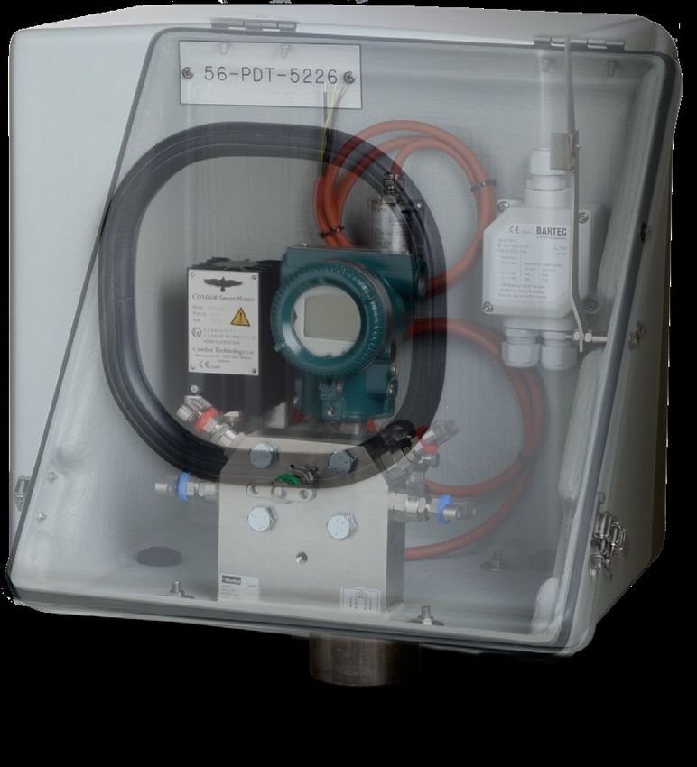
Contents
Introduction......................................................................................................................................................................................... 5
General Technical Information.......................................................................................................................................................... 6
    Design ............................................................................................................................................................................................ 6
    Materials of construction................................................................................................................................................................ 6
    Standard and optional specification details.................................................................................................................................. 7
Connections ....................................................................................................................................................................................... 8
    Integral tubing connections – A Parker Superior Advantage....................................................................................................... 8
    PTFree connectTM........................................................................................................................................................................... 10
    Other connections.......................................................................................................................................................................... 11
    Transmitter flange connections - DIN/IEC 61518......................................................................................................................... 12
Bonnet Assemblies............................................................................................................................................................................ 13
    Standard bonnet design................................................................................................................................................................. 13
    Larger bore bonnet design - Class 2500 (6,000 PSI) and Class 4500 (10,000 PSI).................................................................... 14
    Soft seat tip bonnet design............................................................................................................................................................ 14
    Fire safe bonnet design - Class 2500 (6,000 PSI)......................................................................................................................... 15
    Power plant bonnet design - Compliant to ANSI B31.1 – Class 2500 (6,000 PSI)..................................................................... 15
    Rising plug bonnet design............................................................................................................................................................. 16
    Tru-Loc® safety bonnet lock........................................................................................................................................................... 16
    Low Emission bonnet design......................................................................................................................................................... 17
    Bonnet assembly options.............................................................................................................................................................. 19
Hand Valves & Gauge Valves............................................................................................................................................................ 20
    Introduction..................................................................................................................................................................................... 20
    Hand Valves - HNV Series - Straight Pattern ............................................................................................................................... 21
    Hand Valves - HNAV Series - Angle Pattern ................................................................................................................................ 22
    Gauge Valves - HNVV Series - Single Block Gauge Vent Valves................................................................................................. 23
    Gauge Valves - HGV Series - Multi-port Gauge Valves................................................................................................................ 24
    Rising Plug Valves - HRPV Series.................................................................................................................................................. 25
    Ordering information...................................................................................................................................................................... 26
2-Valve Manifolds - Remote/line Mount.......................................................................................................................................... 28
    Introduction..................................................................................................................................................................................... 28
    2-Valve Manifolds - HNL Series - Remote/line Mount - Long Pattern......................................................................................... 29
    2-Valve Manifolds - Remote/line Mount - Short Pattern.............................................................................................................. 30
    Ordering Information - 2-Valve Manifolds - Remote/Line Mount................................................................................................. 32
    Mounting Brackets for Remote/line Mount Manifolds and Gauge Valves................................................................................... 34
3 and 5-Valve Manifolds - Remote/line Mount............................................................................................................................... 35
    Introduction..................................................................................................................................................................................... 35
    3-Valve Manifolds - Remote/line Mount........................................................................................................................................ 36
    5-Valve Manifolds - Remote/line Mount........................................................................................................................................ 37
    Ordering Information - 3 and 5-valve Manifolds - Remote/line Mount........................................................................................ 38
    Mounting Brackets for Remote/line Mount Manifolds and Gauge Valves................................................................................... 40
2-Valve Manifolds - Direct Mount..................................................................................................................................................... 41
3-Valve Manifolds - Direct Mount..................................................................................................................................................... 42
5-Valve Manifolds - Direct Mount..................................................................................................................................................... 44
    Ordering information...................................................................................................................................................................... 46
    Mounting Brackets for 2, 3 and 5-valve Direct Mount Manifolds................................................................................................. 48
Base Connected Manifolds Especially Suited For Enclosure Mounting.................................................................................... 50
Instrument Enclosure Solutions....................................................................................................................................................... 54
Manifolds for 2051/3051 CoplanarTM Transmitters......................................................................................................................... 55
Essential Manifold Accessories....................................................................................................................................................... 61
Other Manifold Products................................................................................................................................................................... 64
Customer Specific Manifold Solutions............................................................................................................................................ 66
Complementary Products for Complete Installation Solutions .................................................................................................. 68

                                                                                                    3
Introduction
PROCESS              Welcome to the Parker Superior Advantage for your
                     process to instrument hook ups.
                                                                                  The top five target markets for Parker Instrumentation
                                                                                  are shown below, but Parker manifold solutions are

INSTRUMENTATION
                                                                                  suitable for the widest range of process measurement
                     Wholly designed and manufactured from decades
                                                                                  and control applications in a diverse spectrum of
                     of development, experience and knowledge from
                                                                                  industries.
                     within our ISO 9000 compliant UK facility, the Parker

VALVE AND MANIFOLD
                     H-series valve and manifold solutions range enjoys           Continuous product development may from time to
                     world leading recognition for quality, reliability and       time necessitate changes in the details contained in
                     value.                                                       this catalogue. Parker reserves the right to make such

SOLUTIONS
                                                                                  changes at their discretion and without prior notice.
                     Selection can be made from a comprehensive range
                     of bonnet assemblies, body configurations and                All dimensions shown in this catalogue are
                     styles with a variety of connections and material            approximate and subject to change.
                     options to suit all your applications, optimising your       Every effort is made to provide sufficient, clear and
                     installation and improving operation.                        accurate information to allow the correct selection
                     In addition to producing these valves and manifolds          of product from this catalogue, but ultimately it is
                     with your choice of connections, all the products            the system designer’s or user’s responsibility to
                     offered in this catalogue are available (as standard)        ensure selected product is suitable for the intended
                     with the superior advantage of integrated tubing             application. Should you require further information
                     connections. The specification of the world                  please do not hesitate to contact your local Parker
                     renowned and universally acceptable Parker                   support.
                     compression type connections will improve system             With thousands of distributor outlets and stores
                     performance, increase safety, reduce size and                worldwide, and hundreds of Parker personnel and
                     weight and simplify installation which ultimately            locations, Parker also offers the superior advantage of
                     reduces overall user costs.                                  supply and support in your locale.

                     Upstream Oil & Gas      Downstream Oil & Gas         PowerGen               Industrial Gas         Transportation

                     Parker EHS Vision Statement:
                     Parker recognizes, and believes, in the importance of safeguarding natural resources and the global environment.
                     We are committed to our employees, our communities, and our customers: their health, safety and understanding
                     of the need for environmental stewardship.
                     We are committed to the concept of continuous improvement in environmental performance. Accordingly, we are
                     committed to the following principles:
                     • We will seek to comply with environmental, health, and safety laws worldwide.
                     • We strive to minimize or eliminate the generation of waste.
                     • We will monitor compliance with environmental, health and safety regulations.
    4                                                                         5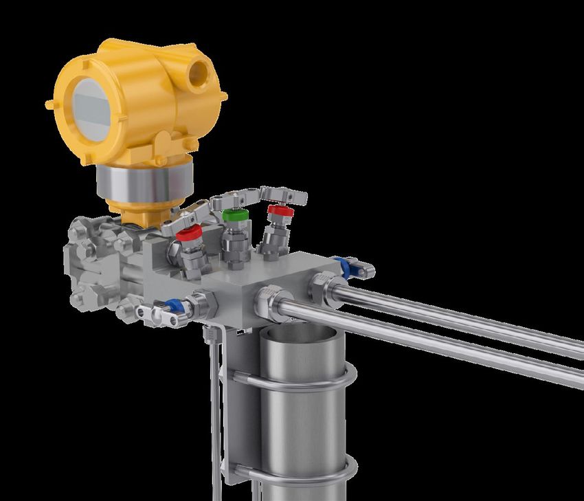
General Technical Information
Design General information - materials of construction
Material
All valves and manifolds are designed to meet the pressure and temperature ratings of ANSI B16.34 Class Item
2500/Class 4500 as applicable, limited only by selection of gland packing materials. Conformity to the St.St. CRA-NiCu Duplex Super Duplex CRA-NiMoCr Titanium 6MO Alloy 825 Alloy 625
recommendations of MSS SP-99 is also assured. Body
316 St.St..
Alloy M400
Duplex Super Duplex
Alloy C276
Titanium
6MO Alloy 825 Alloy 625
ASTM A479 UNS 31803 UNS S32750/32760 GR-2
Relevant codes, standards and specifications Tip
17-4PH
Alloy K500
Duplex UNS
Alloy 625 Alloy B3
Titanium DUPLEX UNS
Alloy 625 Alloy 718
St.St. S.32750/32760 GR-5 S.32750/32760
Code/Specification Description 316 St.St.
Joint Seal Alloy M400 6MO Alloy 625 Alloy C276 Alloy 825 6MO Alloy 825 Alloy 625
ASTM A479
DIN EN61518 / IEC 61518 Mating dimensions between differential pressure (type) measuring instruments
P.T.F.E. / P.T.F.E. / P.T.F.E. / P.T.F.E. / P.T.F.E. / P.T.F.E. / P.T.F.E. / P.T.F.E. / P.T.F.E. /
ASME B31.1 Power Piping Specification for Pipeline Valves Packing
Graphite Graphite Graphite Graphite Graphite Graphite Graphite Graphite Graphite
ASME B16.34 Valves - Flanged, Threaded and Welding End Thrust Bush 316 St.St 316 St.St 316 St.St 316 St.St 316 St.St 316 St.St 316 St.St 316 St.St 316 St.St
ASME B16.5 Pipe Flanges and Flanged Fittings 316 St.St. Duplex UNS Super Duplex Titanium
Stem Alloy M400 Alloy C276 6MO Alloy 825 Alloy 625
ASTM A479 31803 UNS S32750/32760 GR-2
Petroleum and Natural Gas Industries - Materials for use in H2S - containing Environments Gland 316 St.St. 316 St.St. 316 St.St. 316 St.St. 316 St.St. 316 St.St. 316 St.St. 316 St.St. 316 St.St.
NACE MR0175 / ISO 15156 in Oil and Gas Production Adjuster ASTM A479 ASTM A479 ASTM A479 ASTM A479 ASTM A479 ASTM A479 ASTM A479 ASTM A479 ASTM A479
API 598 Valves Inspection and Testing Handle 316 St.St. 316 St.St. 316 St.St. 316 St.St. 316 St.St. 316 St.St. 316 St.St. 316 St.St. 316 St.St.
ISO 5208 Industrial Valves - Pressure Testing of Metallic Valves Grub Screw A4-80 St.St. A4-80 St.St. A4-80 St.St. A4-80 St.St. A4-80 St.St. A4-80 St.St. A4-80 St.St. A4-80 St.St. A4-80 St.St.
Fire Test of Soft-Seated Quarter Turn Valves LDPE - LDPE - LDPE - LDPE - LDPE - LDPE - LDPE - LDPE - LDPE -
Dust Cap
API 607 / ISO 10497 Coloured Coloured Coloured Coloured Coloured Coloured Coloured Coloured Coloured
Fire type-testing requirements
Lock Nut 316 St.St. 316 St.St. 316 St.St. 316 St.St. 316 St.St. 316 St.St. 316 St.St. 316 St.St. 316 St.St.
MSS SP-25 Standard Marking Systems for Valves, Fittings, Flange and Unions 316 St.St. Duplex UNS Super Duplex Titanium
Bonnet Alloy M400 Alloy C276 6MO Alloy 825 Alloy 625
MSS SP-61 Pressure Testing of Valves ASTM A479 31803 UNS S32750/32760 GR-2
MSS SP-99 Instrument Valves Notes:
Max. Working Pressure 6,000 psig (414 barg)
ISO 15848 Industrial valves— Measurement, test and qualification procedures for fugitive emissions High Pressure Range 10,000 psig (689 barg) • CRA-NiCu selection down-rates to 5,000 psig (345 barg)
TA Luft TA-Luft 2002, Absatz 5.2.6.4 und VDI 2440 (Ausgabe Nov. 2000), Absatz 3.3.1.3
• Titanium selection down-rates to 3,950 psig (272 barg)
Temperature Range: • Other materials and option selections can also affect
• P.T.F.E. Packing -54 C to 260 C (-65 F to 500 F)
o o o o
performance ratings. If in doubt, please consult your local
Materials of construction • Graphite Packing -54oC to 538oC (-65oF to 1000oF) Parker support.
All materials are purchased from long standing reputable sources, conforming not only to recognised national/
international standards, but also to additional requirements imposed by Parker to assure suitability/usability Standard and optional specification details
across the widest spectrum of user applications.
Standard Specification Details Optional Specification Details
A range of techniques and processes including PMI (Positive Material Identification) are used to validate all
incoming material supplies, segregation, storage and maintenance of product quality. Seat orifice diameter: 4mm Seat orifice diameter: up to 6mm in some configurations/styles.
See page 14
Body material options Flow co-efficient (Cv): 0.35 6mm - Flow co-efficient (Cv): 0.5
Metal to metal valve seat and stem tip Alternative soft tip and tip materials. See page 14
Material Werkst- ASTM Material
Material Group UNS No. Euronorm Equivalent 100% pressure test. All valves and manifolds are subjected Alternative pressure test regimes applied to oxygen cleaned
Designator off No. Grade and/or low emission products. See page 17
to hydrostatic pressure at 1.1x maximum working pressure
Carbon Steel* A105 UNS 1.0482 19Mn5 K03504 A105 for the seat and 1.5x maximum working pressure for the shell Your other pressure test requirements can be considered
316/316L Dual UNS S31600 1.4401 X5CrNiMo17-12-2 A479 Gr 316 All products supplied in a clean bur and grease free condition Cleaned suitable for oxygen service. Not every product option is
Austenitic Stainless Steel certified suitable for most liquid and gaseous applications suitable for oxygen service
UNS S31603 1.4404 X2CrNiMo17-12-2 A479 Gr 316L Bodies and bonnets are fully traceable to original material Alternative levels of traceability and certification are available.
Super Austenitic Stainless Steel 6Mo UNS S31254 1.4547 X1CrNiMoCuN20-18-7 A479/A276 source (certification with unique trace code applied to the Your other requirements can be considered
bar stock material)
Duplex 22Cr UNS S31803 1.4462 X2CrNiMoN22 5 3 A479/A276 Certification according to BS EN 10204 3.1 for material and Certification according to BS EN 10204 3.2 can be available at
Austenitic-Ferritic Steel UNS S32750 1.4410 X2CrNiMoN25-7-4 A479/A276 pressure test is available additional cost, please contact your local Parker support
(Duplexes) Duplex 25Cr All products are permanently marked. Manifolds include a
UNS S32760 1.4501 X2CrNiMoCuWN25-7-4 A479/A276
line diagram describing the flow paths
Copper-Nickel Alloy Alloy M400 UNS N04400 2.436 NiCu30Fe ASTM B164 Complementary to the marking, bonnet assemblies are all
Nickel Alloy Alloy 825 UNS N08825 2.4858 NiCr21Mo ASTM B425 functionally colour coded by the dust caps
Number of turns open to close: 3.5 6mm - Number of turns open to close: 3.3
Nickel Alloy Alloy 625 UNS N06625 2.4856 NiCr22Mo9Nb ASTM B446
Gauge valves and manifolds do not include plugs as
Nickel Alloy Alloy C276 UNS N10276 2.4819 NiMo16Cr15W ASTM B574 Various plugs are available to order. See page 61
standard
Titanium TitaniumGrade 2 UNS R50400 3.7075 Ti-II ASTM B348 Direct mount manifolds include applicable flange face seals Stainless steel mounting bolts are available. See page 48
and high tensile, zinc plated carbon steel mounting bolts
All materials will meet (as applicable) the requirements of NACE MR0103/MR0175 and ISO 15156. They are A full range of mounting brackets and accessories are available.
further supplied as per NORSOK M650/M630 as required. All manifolds include mounting holes suitable for brackets or See pages 40, 48, 60
* Carbon Steel may not be universally available, and if offered, may be restricted to body only. Other materials enclosure mounting Mounting for selected hand valves and gauge valves is
may be considered but any offer may also be restricted to body only. Please consult with your local Parker available
support.
6 7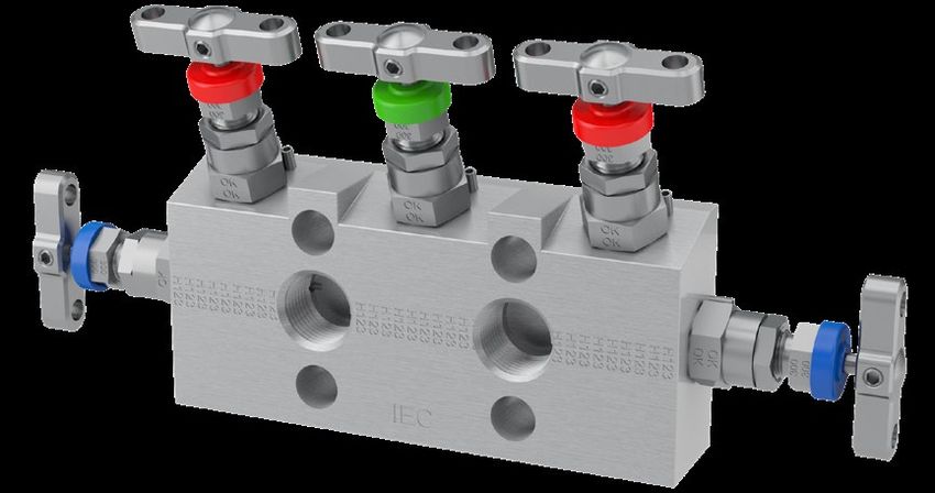
Connections
Introduction                                                                                                           As standard, manifolds are offered with PTFree connectTM style solutions to the inlet connections for direct
                                                                                                                       mount types and also to the outlet connections for remote mount types.
Parker valve and manifold products are available with a wide array of connection types and sizes. These                Other ports (such as vent) are also offered with Parker Instrumentation’s unique PTFree connectTM solution.
products are manufactured at the highest quality to applicable standards, utilising state of the art machinery         Some manifold types can be offered with the inverted design to inlet and outlet connections as applicable.
and processes backed by decades of expertise.

The following pages detail the standard connections available. Other connection types can be considered. If
you can’t find the best connection for your application, please contact your local Parker support.
Please note – not all connection types and sizes will be universally possible across the entire product range.

Integral tubing connections – A Parker Superior Advantage
For the ultimate in safety, reliability, speed and
ease of installation all valves and manifolds can
be specified with solutions offering integral tube
connection utilising Parker A-LOK® (Two Ferrule)
                                                                                                                       5-valve direct mount manifold for differential pressure       5-valve direct mount manifold having the Parker
or CPITM (Single Ferrule) compression fitting                                                                          applications having inlet and vent connections                superior advantage input connections provided
technologies.                                                                                                          provided through the use of PTFree connectTM tube             through inverted tube fitting connections. Vent can
                                                                                                                       fittings.                                                     also be specified as threaded or PTFree connectTM.
For full details of the A-LOK® and CPITM technologies,
please see Catalogue ref. 4190-FMTG.

As standard, hand valves and gauge valves are                                                                          Why the Superior Advantage of an integrated tube connection?
offered with the traditional external thread and nut                                                                   Consider the following simple example with a typical hand valve.
or inverted (internal thread) design to inlet and outlet
connections. Other ports (such as vent) are offered
with Parker unique PTFree connectTM solution (see p.                                                                     Example shown is the widely utilised normal specification of a valve and individual tube fittings to achieve
10).                                                                                                                     the installation.

                                                               HNV series hand valve with traditional type fully                                                                                             Component       Cost
                                                               integrated tube fitting connection.
                                                                                                                                                                                                             Needle valve    1x
                                                                                                                                                                                                             Fittings (2)    1.1x
                                                                                                                                                                                                             Sealant/Tape    0.01x
                                                                                                                                                                                                             Labour          0.15x
                                                                                                                                                                                                             TOTAL           2.26x

                                                                                                                         Example shown is the Parker Superior Advantage fully integrated tube fitting connection.

                                                                                                                                                                                                             Component       Cost
                                                                                                                                                                                                             Needle valve    1.6x
                                                                                                                                                                                                             Fittings (2)    0x
                                                                                                                                                                                                             Sealant/Tape    0x
                                                                                                                                                                                                             Labour          0.05x
                                                                                                                                                                                                             TOTAL           1.65x
HNV series hand valve with the unique Parker fully             HNV series gauge vent hand valve with inverted tube
integrated inverted tube fitting connection.                   fitting to inlet and outlet connections with Parker
                                                               PTFree connectTM tube fitting connection to the vent.
                                                                                                                                                          Integrated tube connections deliver:
                                                                                                                         •   Average 25% saving on installed cost                    •   Zero rework
                                                                                                                         •   Average 55% saving on installation time                 •   Significantly improved safety and system
                                                                                                                                                                                         integrity

                                                           8                                                                                                                     9
Connections
Tube end dimensional data Other connections
Inches Milimeters
†D †D Tapered Pipe Threads - Male and Female
Tube Tube
Size Tube Straight H E Size Tube Straight H E
No. O.D. Thread †C Hex Dia.
Ins.
Depth No. O.D. Thread †C Hex Dia.
Ins.
Depth NPT Tapered Thread BSP Tapered Thread (Code K)
1 1/16 10-32 .43 5/16 .052 .34 2 2mm 5/16-20 15,3 12,0 1,7 12,9 NPT Tapered Thread conforming BSP Tapered Thread conforming
2 1/8 5/16-20 .60 7/16 .093 .50 3 3mm 5/16-20 15,3 12,0 2,4 12,9
to ASME B1.20.1 with enhanced to BS21, ISO7/1 (R ½ - Male.
manufacturing tolerance for Rc ½ Female) with enhanced
3 3/16 3/8-20 .64 1/2 .125 .54 4 4mm 3/8-20 16,1 12,0 2,4 13,7
optimal assembly and inspected manufacturing tolerance for best
4 1/4 7/16-20 .70 9/16 .187 .60 6 6mm 7/16-20 17,7 14,0 4,8 15,3 by three step gauging with Parker optimal assembly and inspected
5 5/16 1/2-20 .73 5/8 .250 .64 8 8mm 1/2-20 18,6 15,0 6,4 16,2 enhanced tolerancing to ANPT using gauging system to BS21.
6 3/8 9/16-20 .76 11/16 .281 .67 10 10mm 5/8-20 19,5 18,0 7,9 17,2 requirement per ASTM SAE
8 1/2 3/4-20 .87 7/8 .406 .90 12 12mm 3/4-20 22,0 22,0 9,5 22,8 AS71051.
10 5/8 7/8-20 .87 1 .500 .96 14 14mm 7/8-20 22,0 24,0 11,1 24,4
12 3/4 1-20 .87 1-1/8 .625 .96 15 15mm 7/8-20 22,0 24,0 11,9 24,4 Parallel Pipe Threads - Male and Female
14 7/8 1-1/8-20 .87 1-1/4 .750 1.03 16 16mm 7/8-20 22,0 24,0 12,7 24,4
BSP Parallel Thread – Default BSP Parallel Gauge connection
16 1 1-5/16-20 1.05 1-1/2 .875 1.24 18 18mm 1-20 22,0 27,0 15,1 24,4 standard (Code R) type – Optional (Code RD)
20 1-1/4 1-5/8-20 1.52 1-7/8 1.09 1.61 20 20mm 1-1/8-20 22,0 30,0 15,9 26,0 BSP Parallel Thread conforming According to DIN 16284/16288/
24 1-1/2 1-15/16-20 1.77 2-1/4 1.34 1.96 22 22mm 1-1/8-20 22,0 30,0 18,3 26,0 to BS2779, ISO 228/1+2, DIN DIN EN 837.
32 2 2-5/8-20 2.47 2-3/4 1.81 2.65 3852. Not available on all product/ Thread conforming to BS2779,
25 25mm 1-5/16-20 26,5 35,0 21,8 31,3
model types, please consult with ISO228/1+2, DIN 3852.
Not available on all product/model
Notes: your local Parker support. types, please consult with your
• Dimensions C and D are shown in the finger-tight position. local Parker support.
• † Average value
• Dimensions for reference only, subject to change.
Weld Connections
Butt Weld (Code BW)
Socket Weld (Code SW/MSW) Butt Weld connection suitable for
PTFree connectTM Female or male Socket Weld
connection suitable for pipe
pipe conforming to ASME B16.25,
EN12627.
Many users desire the elimination of taper threads and their conforming to ASME B16.11,
associated sealant. EN12760.
The PTFree connect™ system enables users to assemble tube
lines to any of the manifold ports without the need for PTFE
tape or liquid sealant. Notes: Notes:
• Valves with female socket weld connections will be of Valves with butt weld connections will, as standard, be
the same length as per the equivalent NPT pipe threaded of the same length as per the equivalent male NPT pipe
The PTFree connect™ connection can be applied to any of variants. threaded variants.
the manifolds featured in this catalogue. These will be factory • Valves with male socket weld connections will, as
fitted, pin locked and pressure tested. standard, have a stub length increase of 1/2” (13mm) Other Notes:
when compared to the male pipe threaded equivalent • For valves with welded connections, special
variants. consideration must be given to the installation/welding
PTFree connect™ enables angled tube connections to be AA Pipe size Dimension (A) process. Care must be taken to ensure that the central
swivelled to achieve optimum tube alignment. Assembly to the 4 (1/4" NB) 29
valve body and bonnet assembly sections are not
tube connector is achieved by tightening the standpipe nut harmed by the process itself and to further protect these
E
C
6 (3/8" NB) 29
Pipe Size (NB) Length 'A'
elements from injurious heat transfer.
4 [1/4" NB] 29
one-quarter turn from the finger-tight position.
6 [3/8" NB] 29
8 [1/2" NB] 32
8 (1/2" NB) 32
12 [3/4" NB] 35
SECTION C-C
SCALE 1 : 1 12 (3/4" NB) 35 • Connection ratings: Certain weld connections can
Manifolds can also be supplied with male connectors using the same thread form as the PTFree connect™. They Optional lengths: impact published performance ratings of the manifold.
are provided factory fitted, pin locked and tested. If requested, male socket welds or butt welds can be Care should be taken in the selection of connections
Some size restrictions may be necessary due to the close proximity of some connections and the across flat offered with stub length of 75mm or 100mm. to ensure they meet application expectations for
hexagon dimensions. As a guide, PTFree connect™ for inlet and outlet can be up to 1/2” or 12mm o/d, drain/bleed DETAIL E performance. For example: Butt weld or tube fitting
75mm
SCALE 2 : 1
OPTIONAL LENGTHS
connections with a thinner wall section, may result
connections should be restricted to 1/4” or 6mm. For PTFree connect™ male connectors inlet and outlet should be
75.0 and 100.0mm
or 100mm
in a reduced pressure performance capability when
restricted to 3/8” or 10mm and 1/4” or 6mm o/d for drain/bleed. E C
compared to that of the published. Please consult
relevant Parker publications or consult with your local
A PTFree connect™ A PTFree connect™ Parker support.
tube stub male connector SECTION C-C
SCALE 1 : 1
(Code PF) (Code PFC) Flange Connections
Tube size Dimension (A) Tube size Dimension (A) Process Flange Instrument Flange (Code HK)
Flange connections can be DETAIL E
SCALE 2 : 1 DIN/IEC 61518 compliant
6mm 10
22.26mm 0.88” 6mm 26.90mm 0.95” considered if conforming to ANSI instrument (kidney/oval) flange
1/4” 24.80mm 0.98” 1/4” 24.10mm 0.84” B16.5 and executed in various connections.
10mm/3/8” 26.40mm 1.04” 10mm/3/8” 27.70mm 1.09” ways. Please consult your local
12mm/1/2” 32.10mm 1.26” 12mm/1/2” 30.30mm 1.20” Parker support.
Not available on all product types.
10 11
Connections Bonnet Assemblies
Transmitter flange connections - DIN/IEC 61518 Standard bonnet design
As standard, Parker manifolds have inlet and outlet gas or vapours. The maximum allowable temperature Class 2500 (6,000 PSI) and Class 4500 (10,000 PSI)
interface connections in full accordance with DIN/IEC of 120°C (248°F) considers the requirement that
61518. For the Manifold to Transmitter interface, the manifolds and transmitters need to be protected
For safe, reliable and repeatable performance
type B connection is standard, type A is optionally against undue heating by hot media. This requirement
available. should be achieved by using adequate hook-ups or
by instrument impulse lines with sufficient length. Reference Description
Within DIN/EN 61518 the manifold-transmitter However, Parker confirms that H series manifolds can 1
interface is rated for maximum allowable working be used for temperatures up to 538°C (1,000°F) with Ergonomic ‘T’ bar style handle with positive
1
pressure of 413 bar (6,000 psi) and maximum graphite gland packing and up to 260°C (500°F) with retention
allowable temperature of 120°C (248°F) for liquids, PTFE gland packing. 2
Dual purpose dust cap provides functional
2
identification
Process inlet to manifold / transmitter interface DIN EN 61518 / IEC 61518 3 3 Compensatory adjustable gland
�
54.0 0.3
54.0±0.3
≥15.0
15.0 � 4 4 Secure anti-vibration gland lock nut
5 Anti-blowout low torque back seating stem
7 6
6 All metal body bonnet seal
20.65±0.2
20.65 0.2
5 Gland thrust bush ensures uniform packing
7
+0.3
+
18.5 -
ø18.5
0.3 41.3 0.2
41.3±0.2
compression and tight sealing
0.0
-0.0
Annealed sealing washer guarantees 100%
Reference Description 8
1) 1 sealing assurance
Threaded option for transmitters - Self-centering, non-rotating stem tip
1 9
plug/vent valve guarantees bubble tight shut off
+ 0.5
2.5 +0.5
A 2.5 --0.0
0.0 Material traceability for major pressure
10
containing components
Parker 1)manifold outlet
Threaded option for transmitters to valve
- plug/vent transmitter interface DIN EN 61518 / IEC 61518
Type B and Type A
Type B Type A
54.0 0.1
54.0±0.1 54.0 0.1
B
8 9 10
++0.2
0.2
ø11.8
11.8 - -0.0
0.0 + 0.2 C
11.8 -
0.0
Notes:
• As standard, all metallic parts are 316 Stainless Steel. Optional materials are available, please see page 6.
20.65 0.1
20.65±0.1 20.65 0.1 • For products specified in optional materials, non-wetted parts will be 316 Stainless Steel as standard.
41.3 0.2 +0.0
+ 0.0
19.9 -
+0.0
+ 0.0
25.5 -
+ 0.0
+0.0 +0.0
+ 0.0 • 6,000 PSI bonnet thread is M16; 10,000 PSI bonnet thread is M18.
41.3±0.2 ø19.9 0.1 ø25.5
-0.1 0.1 41.3 0.2
-0.1 18.0 -
ø18.0 -0.1
25.2 -
0.1 ø25.2 0.1
-0.1
25.2
2.0
++0.1
0.1
2.0- 0.0 +0.1
+ 0.1 1.9
Pressure vs temperature
-0.0 1.81.8 -B-B
-0.0
SECTION 0.0 2.3
SCALE 1.25
+0.0 Pressure
+ 0.0
2.4 - 0.3
2.4 -0.3 psi (bar) Reference Description
Type B (Standard) Type A (Optional)
SECTION A-A
A A-A Graphite packing
10,000 SCALE 1.25
DETAIL C
SCALE 1.25
(690) A-B PTFE packing
Max. Allowable Working Pressure 413 bar (6,000 PSI) 413 bar (6,000 PSI)
8,000 B-B 6,000 PSI (414 bar) standard PTFE packing
PTFE: Graphite: PTFE: Graphite: (552)
Temperature range -10OC to +80OC -40OC to +120OC -10OC to +80OC -15OC to +120OC 6,000 PSI (414 bar) standard Graphite
6,000 B B-C
(14OF to 176OF) (-40OF to 248OF) (14OF to 176OF) (5OF to 248OF) (413)
packing
DETAIL B
SCALE 1.25
Flat Ring Flat Ring Flat Ring Flat Ring
4,000
Seal ring 25.4 x 20 x 2.7 25.4 x 19.9 x 2.9 24 x 17.7 x 2.7 25.1 x 18.0 x 2.9 (275)
Notes:
Material: PTFE Material: Graphite Material: PTFE Material: Graphite
2,000 • Pressure and temperature ratings shown are
Min. Thread Engagement 9mm 9mm (138) maximum possible values. Continuous operation at
Spare/Replacement Seal part No. HIEC001-PTFE/1 HIEC001-GRAPHITE/1 HIEC002-PTFE/1 HIEC002-GRAPHITE/1 B C A the maximum ratings will reduce life expectancy.
0
Temperature • Pressure and temperature ratings can be derated by
Connection at the manifold acc. to DIN/IEC 61518. 0 100 200 300 400 500 °C (°F) certain connection types or materials of construction.
(32) (212) (392) (572) (752) (932)
Important Note - there are some exceptions to the IEC 61518 standard:
1. Emerson CoplanarTM transmitter design. Parker offers a full range of specifically suitable manifolds for this type. See
pages 55-60.
2. There is a limited range of other higher working pressure transmitters by some manufacturers, where the interface is
proprietary by design (Example: Yokogawa EJX 440A/EJA 440E). Parker is able to provide manifold designs that are
complementary to those products. Please consult your local Parker support.
12 13
Bonnet Assemblies
Larger bore bonnet design Fire safe bonnet design - Class 2500 (6,000 PSI)
Class 2500 (6,000 PSI) and Class 4500 (10,000 PSI) Features
Features • Specifically designed and developed to meet
exacting industry requirements, products
• 6mm seat orifice size, allowing the provision of incorporating this Bonnet Design conform to BS
larger 5mm or 6mm flow passages 6755 Part 2, API 6FA / API607. For further details
• Ideal for applications with dirtier/denser service contact your local Parker support.
media and/or those prone to blocking in small • 100% fire safe design certified, many typical
bore installations actual third party test certificates are available for
• Can enhance other aspects of performance and review
measurement accuracy • Available for most product styles and types
• Will result in the use of larger body material sizes • Some material selections are restricted
• Not possible for all styles and types of product
• All other technical information remains
unchanged from standard
Power plant bonnet design
Compliant to ANSI B31.1 – Class 2500 (6,000 PSI)
Soft seat tip bonnet design
Features
Features
• Available in a select range of body styles and
• Available in the 4mm orifice size only, this PEEK types. Please consult your local Parker support
seat tip option is available for all product styles • Designed specifically to meet the requirements
and types of ANSI B31.1 (Power Plants) and B31.3
• Ideal for clean gaseous or other services where (Petrochemical Plants) including materials of
bubble-tight shut-off with minimum effort is construction, these bonnet assemblies are
required Graphite packed for higher temperature service
• Suitable for temperatures up to 204oC and • Suitable for temperatures up to 538oC
pressures up to 10,000 psi at reduced and pressures up to 6,000 psi at reduced
temperature, as per graph temperature, as per graph
• For larger bore requirements Parker recommends • Unique patented Tru-Loc® safety bonnet lock
Rising Plug valve further enhances security in application
Pressure vs temperature Pressure vs temperature
Pressure
psi (bar) Pressure
psi (bar)
10,000 A 7,000
(690) (483)
6,000
8,000 (414)
(552) 5,000
(345)
6,000
(413) To order valves and manifolds with power plant bonnet 4,000
design, follow the part builder structures as on pages 26-27, (276)
4,000 32-33, 46-47 and replace H in the series names with HPP. 3,000
Reference Description (275) (207)
C Consult your local Parker support for available options.
A-D PEEK tip 2,000
2,000 (138)
(138)
PCTFE tip - Temperature limit 150°C (302°F) Examples: 1,000
C-E (69)
at 3,000 psi (207 bar) E D HPPNVS8FF3 - Hand valve
0
Temperature HPPLS2V3 - 2-valve remote mount flat barstock manifold 0
HPPLS5M3 - 5-valve remote mount flat barstock manifold Temperature
0 100 200 300 400 500 °C (°F) -18 38 93 149 204 260 316 371 427 482 538 °C (°F)
(32) (212) (392) (572) (752) (932) HPPDS5M3 - 5-valve direct mount flat barstock manifold (0) (100) (200) (300) (400) (500) (600) (700) (800) (900) (1,000)
14 15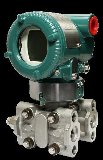
Bonnet Assemblies
Rising plug bonnet design Low emission bonnet design
Features TA-Luft compliant
• HRPV valve is unique to Parker and is patent- As standard, products fitted with the Parker Instrumentation standard bonnet assembly are bubble tight
protected in service and have been proven to meet the requirements of TA-Luft 2002, Absatz 5.2.6.4 und VDI 2440
• Non-rotating plug/tip (Ausgabe Nov. 2000), Absatz 3.3.1.3.
• Dynamic response moulded seat insert with
guaranteed alignment
• Standard straight through orifice size: 1/4” (6.4mm)
IS0 15848 compliant
• Cv: 1.8 From 2007 EU’s IPPC directive 96/61/EC legislates Parker Instrumentation specifically developed an H
• Rolled spindle operating threads for the minimisation of pollution from industrial series Bonnet Assembly design with class A approval
• Straight through flow path sources (Many other regions and countries have to ISO 15848-1. Classed ‘FE’, products specified with
• Multi-port gauge style available as standard. Other similar legislation). An important part of this legislation these bonnet assemblies are certified as
styles can be considered - please consult the is reducing Ultra-Low emissions. According to the ISO FE AH-C01-SSA1-t(RT,180°C)-ANSI2500-ISO
factory IPPS, all plants and factories which fail to comply 15848-1. These products are further classified as
with the standards set by the directive, may face meeting the ISO 15848-1 standard with the following
• Bi-directional flow closure. criteria;
• Backstop spindle for blowout prevention and
minimal atmospheric leakage The legislation introduced a concept of Best Available • Class A tested with Helium
• Low torque operating T bar handle Technique (BAT), urging plants to find the best • Endurance class C01 – a mechanical valve which
• Externally adjustable gland available solution for reducing Ultra-Low emissions has been tested throughout 500 mechanical
• Full range of head options available throughout all processes. With respect to valves, actuations with two thermal cycles
ISO 15848 parts 1 and 2 were developed to aid • Temperature class RT-180°C – fully thermal
Pressure vs temperature • Dust cap to prevent ingress of contamination to companies to meet the legislation. cycled and tested from -29°C to +180°C pressure
operating thread
Pressure class ANSI 2500 – 6000 psi in 316 Stainless
psig (bar) • Bonnet locking pin fitted as standard Part 1 covers the classification system and Steel.
• Suitable for temperatures up to 204oC and qualification procedure for type testing of valves. The
10,000
(689)
A pressures up to 10,000 psi at reduced temperature, standard specifies three tightness classes of leakage Part 2 of the standard covers production acceptance
as per graph with respect to stem sealing diameter. These classes testing of valves. This production testing can only
8,000 are class A, B and C; class A having the smallest be carried out to product which has already been
(552)
environmental leakage. Each class level is one approved to part 1 of the standard. Parker can offer
6,000 hundred fold lower than the class above i.e. a class production testing and certification to a sampling
(414)
B product may have a leakage of 100 times that of a percentage specified by the purchaser. A third party
4,000 class A product. The standard also specifies the duty witnesses can also be considered.
(275)
that the valve has been tested to.
2,000
(138)
Reference Description
A
0
Temperature
A-A PEEK Seat
0 100 200 300 400 500 °C (°F)
(32) (212) (392) (572) (752) (932)
Tru-Loc® safety bonnet lock
Available as standard on ANSI/ASME B31.1 manifold
versions, the unique Parker Tru-Loc® security locking
system is applied to the body to bonnet interface
but can also be applied to many other screwed
component interfaces. Extensive tests have proven
that threaded connection interfaces secured with
Tru-Loc® guarantee 100% security in preventing
movement between connected components. In the H
series manifolds it prevents loosening or removal of
the bonnet assembly by any means.
16 17
Bonnet Assemblies
Low emission bonnet design Bonnet assembly options
Available as a factory fit or as retrofit, these useful bonnet assembly options are provided in all 316 Stainless Steel
Reference Description material. For locking options padlocks are not provided but the hole size in all cases is 6mm (0.24”). To obtain
1 1 Positive handle retention factory fit options, your specified product part number must be suffixed with the additional option part numbers
2
as below. Some options can be combined.
2 “T” bar
3
3 Dust cap
4 6 7 8 4 Gland packing adjuster
5 Gland adjuster lock nut
5 T bar handle locking Handwheel
6 Thrust bush
Retrofit Kit Factory Fitted Retrofit Kit Factory Fitted
7 Gland packing (adjustable) Part Suffix Part Suffix
Number Number
8 Valve bonnet
9 KITTHL HL KITTHW HW
9 Anti blow-out spindle
10
10 Anti extrusion ring
11 Elastomeric o-ring (stem seal)
12 Anti-extrusion ring
13 Elastomeric o-ring (body seal)
14 Bonnet end cap Anti-tamper spindle Lockable handwheel
15 Spindle tip Retrofit Kit Factory Retrofit Kit Factory Fitted
Part Fitted Part Suffix
Number Suffix Number
With KITLHW LHW
KITAK ATK
12 13 15 11
Key
14
Without KITAT AT
Key
Pressure vs temperature Features
Pressure
• Tightness class A≥1 x 10⁻⁶ mg.s-1.m-1
psi (bar) • Maximum cold working pressure rating 6,000
psig (414 barg) Key Anti-tamper handwheel
6,000 AB
(413) • Temperature rating -29˚C to 180˚C (-20˚F to 356˚F)
Key only Key only
• ISO15848-1 prototype tested using global helium Part Number Part Number
vacuum method ATHKEY ATHWKEY
• Performance class –
4,000 AC ISO FE AH-C01-SSA1-t(RT,180°C)-ANSI2500-ISO
(275)
B 15848-1
C • Production testing and certification available on
request )
2,000 • O–ring material grade is Fluoroelastomer FKM
(138)
Tetrapolymer, specially formulated for explosive
decompression (ED) resistance. These seals Panel mounting
are qualified to the stringent NORSOK M-170
standard covering both ED resistance and sour Retrofit Kit Factory Fitted
E
0 Part Suffix
Temperature gas (H2S) ageing tests Number
0 60 120 180
(32) (140) (248) (356)
°C (°F) • Available for most product styles and types KITPM PM
• Also meets the requirements per;
TA-Luft according to VDI 2440 as tested by TUV Hole 26mm (1.02”)
Reference Description SUD Industrie Service GMBH performing better Diameter
A-A Graphite packing than a leakage rate of Panel Max. 5mm (0.20”)
VDI 2440 = 10 -4 mbar .l /s . m Thickness Min. 2.3mm (0.09”)
A-B PTFE packing
B-B 6,000 PSI (414 bar) standard PTFE packing Min.
distance
6,000 PSI (414 bar) standard Graphite for panel 51mm (2.00”)
B-C packing mount
spacing
A-D PEEK tip
C-E PCTFE tip
18 19Hand Valves & Gauge Valves Hand Valves - HNV Series
Introduction Straight pattern
Following years of valve design and development, the Parker needle pattern hand and gauge valves range is
one of the most comprehensive to be found. The valves are available to users from a wide market spectrum HNV* - Integral A-LOK® connections - up to 6,000 PSI
and are suitable for all industries and applications. Inlet Outlet Dimension
A B C
In combination with Parker A-LOK or CPI compression tube fitting technologies, a superior advantage
® TM A-LOK ®
A-LOK ®
mm (inch) mm (inch) mm (inch)
is gained allowing users to eliminate threaded connections and reduce leak paths whilst offering superior
C
C 1/4” 1/4” 67.5 (2.66”) 25.4 (1.00”) 76.2 (3.00”)
installation and operational performance.
1/2” 1/2” 76.2 (3.00”) 25.4 (1.00”) 76.2 (3.00”)
6mm 6mm 67.5 (2.66”) 25.4 (1.00”) 76.2 (3.00”)
Reference Description
AA BB
12mm 12mm 76.2 (3.00”) 25.4 (1.00”) 76.2 (3.00”)
1 Locked grub screw
1 2
2 “T” bar handle
HNV* - Integral CPITM connections - up to 6,000 PSI
3 Dust cap
3
Inlet Outlet Dimension
4 Gland packing adjuster
4 A B C
CPI TM
CPI TM
5 Gland adjuster lock nut mm (inch) mm (inch) mm (inch)
5 6 Valve bonnet
C 1/4” 1/4” 67.5 (2.66”) 25.4 (1.00”) 76.2 (3.00”)
7 Integral A-LOK connection
®
1/2” 1/2” 76.2 (3.00”) 25.4 (1.00”) 76.2 (3.00”)
6 8 Body 6mm 6mm 67.5 (2.66”) 25.4 (1.00”) 76.2 (3.00”)
12mm 12mm 76.2 (3.00”) 25.4 (1.00”) 76.2 (3.00”)
A B
7
Integral connections - up to 10,000 PSI
8 A limited range of integral connections for 10,000 PSI is available as tube selection can adversely affect overall
product ratings. Please consult your local Parker support.
With their small ports and needle/plug stem tip, HNV* - Female threaded - NPT
Parker hand valves allow precise regulation of flow in Inlet Outlet Dimension
low flow applications for a wide variety of media. Pressure
(PSI) A B C
Female Female mm (inch) mm (inch) mm (inch)
These hand valves are widely used in situations
C 1/4” NPT 1/4” NPT 54.0 (2.13”) 28.6 (1.13”) 79.4 (3.13”)
where the flow must be gradually brought to a halt
and at other points where precise adjustments of flow Example shown: Multi-port gauge valve with Parker 6,000 3/8” NPT 3/8” NPT 54.0 (2.13”) 28.6 (1.13”) 79.4 (3.13”)
are necessary or where a small flow rate is desired. Superior Advantage integral A-LOK® tube fitting
1/2” NPT 1/2” NPT 63.5 (2.50”) 28.6 (1.13”) 79.4 (3.13”)
They can be used as both on/off valves and for connections.
throttling service. They are used in every industry in a wide range of
A B 1/4” NPT 1/4“ NPT 60.5 (2.38”) 31.8 (1.25”) 82.6 (3.25”)
10,000
applications - anywhere where accurate and secure 1/2” NPT 1/2” NPT 69.9 (2.75”) 31.8 (1.25”) 82.6 (3.25”)
control or metering of steam, air, gas, oil, water or
HNV* - Male x Female threaded - NPT
other non-viscous liquids is required.
Inlet Outlet Dimension
Pressure
Utilising these same attributes, the Parker needle (PSI) A B C
pattern gauge valves will be found controlling flow Male Female mm (inch) mm (inch) mm (inch)
into a vast array of measurement and analysis 1/4” NPT 1/4” NPT 57.8 (2.27”) 28.6 (1.13”) 79.4 (3.13”)
C
instrumentation such as pressure gauges, 6,000
transmitters, switches and more. With additional 1/2” NPT 1/2” NPT 73.0 (2.87”) 28.6 (1.13”) 79.4 (3.13”)
functionality these gauge valves also allow users 1/4” NPT 1/4” NPT 62.8 (2.47”) 31.8 (1.25”) 82.6 (3.25”)
to provide vent, drain or blowdown routes to their 10,000
A B
1/2” NPT 1/2” NPT 76.2 (3.00”) 31.8 (1.25”) 82.6 (3.25”)
process and/or the ability to attach additional
instruments and accessories.
We are confident you will find a valve style, type Notes:
and connection option to suit your applications, but • Dimension “A” given for finger-tight nuts and ferrules.
should you require something different please contact • Dimension “C” in open position.
Example shown: Hand valve with Parker Superior your local Parker support.
Advantage integral CPITM tube fitting connections.
20 21Hand Valves - HNAV Series Gauge Valves - HNVV Series
Angle pattern Single block gauge vent valves
Generally used in conjunction with the measuring
HNAV* - Integral A-LOK® connections - up to 6,000 PSI instrument, these valves allow for the function of
Inlet Outlet Dimension
venting/draining any process media that may be
trapped, following isolation of the instrument for
A B C
A-LOK ®
A-LOK ®
mm (inch) mm (inch) mm (inch) maintenance and/or removal purposes.
CC C 1/4” 1/4” 58.4 (2.30) 30.1 (1.19) 100.8 (3.97)
1/2” 1/2” 62.9 (2.48) 30.1 (1.19) 105.3 (4.15)
6mm 6mm 58.4 (2.30) 30.1 (1.19) 100.8 (3.97)
12mm 12mm 62.9 (2.48) 30.1 (1.19) 105.3 (4.15)
A AA BB B
Example shown: HNVV single block gauge vent valve
with Parker Superior Advantage integral inverted A-LOK®
HNAV* - Integral CPITM connections - up to 6,000 PSI tube connections to inlet and outlet and with Parker
PTFree connectTM to the vent.
Inlet Outlet Dimension
A B C
CPITM CPITM mm (inch) mm (inch) mm (inch) HNVV* - Male x Female threaded - NPT
CC C 1/4” 1/4” 58.4 (2.30) 30.1 (1.19) 100.8 (3.97) Inlet Outlet Vent Dimension
Pressure
1/2” 1/2” 62.9 (2.48) 30.1 (1.19) 105.3 (4.15)
Female Female mm A
(PSI) B C
Male (inch) mm (inch) mm (inch)
6mm 6mm 58.4 (2.30) 30.1 (1.19) 100.8 (3.97)
C 1/4” NPT 1/4” NPT 1/4” NPT 72.5 (2.85) 28.6 (1.13) 79.4 (3.13)
12mm 12mm 62.9 (2.48) 30.1 (1.19) 105.3 (4.15) 6,000
A AA BB B 1/2” NPT 1/2” NPT 1/4” NPT 85.8 (3.38) 28.6 (1.13) 79.4 (3.13)
1/4” NPT 1/4” NPT 1/4” NPT 71.2 (2.80) 31.8 (1.25) 82.6 (3.25)
Integral connections - up to 10,000 PSI B
10,000
1/2” NPT 1/2” NPT 1/4” NPT 85.6 (3.37) 31.8 (1.25) 82.6 (3.25)
A
A limited range of integral connections for 10,000 PSI is available as tube selection can adversely affect overall
product ratings. Please consult your local Parker support.
HNVV* - Female x Female threaded - NPT
HNAV* - Female threaded - NPT Inlet Outlet Vent Dimension
Pressure
Female Female Female mm (inch) mm B
(PSI) A C
Inlet Outlet Dimension (inch) mm (inch)
A B C C
1/4” NPT 1/4” NPT 1/4” NPT 63.5 (2.50) 28.6 (1.13) 79.4 (3.13)
Female Female mm (inch) mm (inch) mm (inch) 6,000
1/2” NPT 1/2” NPT 1/4” NPT 76.3 (3.00) 28.6 (1.13) 79.4 (3.13)
C
1/4” NPT 1/4” NPT 49.5 (1.95) 25.4 (1.00) 88.3 (3.47)
1/4” NPT 1/4” NPT 1/4” NPT 69.0 (2.71) 31.8 (1.25) 82.6 (3.25)
1/2” NPT 1/2” NPT 54.3 (2.14) 28.6 (1.13) 101.0 (3.98) 10,000
A
1/2” NPT 1/2” NPT 1/4” NPT 79.5 (3.13) 31.8 (1.25) 82.6 (3.25)
B
A B HNVV* - Male x Male threaded - NPT
Inlet Outlet Vent Dimension
HNAV* - Male x Female threaded - NPT Pressure
Female mm A
(PSI) B C
Male Male
Inlet Outlet Dimension (inch) mm (inch) mm (inch)
C 1/4” NPT 1/4” NPT 1/4” NPT 76.2 (3.00) 28.6 (1.13) 79.4 (3.13)
A B C
Male Female 6,000
mm (inch) mm (inch) mm (inch)
1/2” NPT 1/2” NPT 1/4” NPT 94.8 (3.73) 28.6 (1.13) 79.4 (3.13)
CC 1/4” NPT 1/4” NPT
C 49.5 (1.95) 30.1 (1.19) 98.7 (3.89)
1/4” NPT 1/4” NPT 1/4” NPT 76.2 (3.00) 31.8 (1.25) 82.6 (3.25)
1/2” NPT 1/2” NPT 54.3 (2.14) 30.1 (1.19) 102.2 (4.02) 10,000
A
B
1/2” NPT 1/2” NPT 1/4” NPT 94.8 (3.73) 31.8 (1.25) 82.6 (3.25)
A
Notes:
A A
BB B
• Dimension “A” given for finger-tight nuts and ferrules.
• Dimension “C” in open position.
• For bleed/vent valves and plugs see page 61.
Notes:
• Dimension “A” given for finger-tight nuts and ferrules.
• Dimension “C” in open position. Products shown here can be supplied with integral swivel gauge adaptor as shown on page 24.
22 23Gauge Valves - HGV Series Rising Plug Valves - HRPV Series
Multi-port gauge valves These unique, high quality, high performance,
Parker’s multi-port gauge valves are purpose low-torque rising plug soft-seated valves have
designed valves for operation up to 6,000 psig been specifically designed to perform with fluids
(414 barg) and 10,000 psig (689 barg). Featuring as containing high levels of contamination, such as
standard PTFE gland packing and self-centering those frequently found in oil and gas processing
non-rotational tip for bubble-tight seat shut-off, these facilities. With a straight through flow pattern and
valves give the user the assurance of safety and 100% repeatable bubble-tight shut-off, the valves as
performance. standard with PEEK seat will perform up to 10,000
psig (689 barg) with low spindle operating torques.
Example shown: Multi-port gauge valve with Example shown: Hand valve with integral A-LOK®
integral A-LOK® connections. connections.
HGV* - Male x Female (3 outlets) threaded - NPT HRPV4* - Male x Female threaded - NPT
Inlet Outlet Dimension Inlet Outlet Dimension
A B C A B C
Male Female Male Female
mm (inch) mm (inch) mm (inch) mm (inch) mm (inch) mm (inch)
C
1/4” NPT 1/4” NPT 72.5 (2.85) 28.6 (1.13) 79.4 (3.13) C
1/2” NPT 1/2” NPT 72.9 (2.87) 31.8 (1.25) 88.0 (3.46)
1/2” NPT 1/2” NPT 92.0 (3.62) 28.6 (1.13) 79.4 (3.13)
3/4” NPT 1/2” NPT 72.9 (2.87) 31.8 (1.25) 88.0 (3.46)
A B C
Male Male* mm (inch mm (inch) mm (inch)
A
B
1/2” NPT 1/2” NPT 97.2 (3.82) 28.6 (1.13) 79.4 (3.13) A B
*Optional outlet
HRPV4* - Female x Female threaded - NPT
HGVX* - Male Extended x Female (3 outlets) threaded - NPT
Inlet Outlet Dimension
Inlet Outlet Dimension
A B C
A B C D Female Female
Male Female
mm (inch) mm (inch) mm (inch) mm (inch)
mm (inch) mm (inch) mm (inch)
D C
C 1/2” NPT 1/2” NPT 148.0 (5.83) 28.6 (1.13) 79.4 (3.13) 75.0 (2.95)* 1/4” NPT 1/4” NPT 60.5 (2.38) 31.8 (1.25) 88.0 (3.46)
* Example part numbers: 1/2” NPT 1/2” NPT 69.8 (2.75) 31.8 (1.25) 88.0 (3.46)
• 1/2” NPT Male inlet - default extension: 75mm (2.95”), 1/2” NPT
Fem. outlet = HGVXS8M8F
A B
• 1/2” NPT Male inlet - optional extension: 100mm (3.94”), 1/2” NPT
Fem. outlet = HGVXS12MD8F (add D for 100mm extension) A
B
HGVWG* - Male x Female (2 outlets) threaded - NPT with integral swivel gauge adaptor HRPV4G* - Male x Female (3 outlets) threaded - NPT
Inlet Outlet Dimension
Inlet Outlet Dimension
A B C
Male Female A B C
mm (inch) mm (inch) mm (inch) Male Female mm (inch) mm (inch) mm (inch)
C 1/2” NPT 1/2” BSPP 140.8 (5.54) 28.6 (1.13) 79.4 (3.13) C
1/2” NPT 1/2” NPT 96.5 (3.80) 31.8 (1.25) 88.0 (3.46)
• Swivel adaptor to the outlet is provided through a socket weld,
generally conforming to ANSI B16.11.
• Weld connection is a “commercial weld”, completed by a qualified
A
B
welder. Any specific qualification, certification, documentation or
additional NDT, will require to be engineered and quoted extra – B
A
please consult your local Parker support.
• Union nut dimensions generally conform to DIN 16284 as it
applies to the union of nipple & nut themselves.
• Union nut also conforms generally to DIN EN 837 for the gauge HRPV4* - Integral A-LOK® connections
HGV* - Female x Female (3 outlets) threaded - NPT connection itself, as it applies to the union of nipple and nut
themselves.
Inlet Outlet Dimension
A B C
A-LOK A-LOK mm (inch) mm (inch) mm (inch)
Inlet Outlet Dimension C
C
1/2” 1/2” 63.5 (2.50) 31.8 (1.25) 88.0 (3.46)
C A B C
Female Female mm (inch) mm (inch) mm (inch) 12mm 12mm 63.5 (2.50) 31.8 (1.25) 88.0 (3.46)
1/2” NPT 1/2” NPT 82.5 (3.25) 28.6 (1.13) 79.4 (3.13)
A
A B
B Products shown here can be supplied with
A
B
Notes: integral swivel gauge adaptor as shown on
Notes: • Dimension “A” given for finger-tight nuts and ferrules. page 24.
• Dimension “A” given for finger-tight nuts and ferrules. • Dimension “C” in open position.
• Dimension “C” in open position. 24 25You can also read