Two-Dimensional Movement Photovoltaic Cleaning Robot with Speed Control
←
→
Page content transcription
If your browser does not render page correctly, please read the page content below
International Journal of Mechanical Engineering and Robotics Research Vol. 11, No. 3, March 2022 Two-Dimensional Movement Photovoltaic Cleaning Robot with Speed Control 1 Ayat A. Al-Jarrah, 2 Rami A. Al-Jarrah ,1 Fadwa W. Al-Momani, 1 Mohammad Ababneh, and 3 Manar B. Al- Hajji Department of Mechatronics Engineering, The Hashemite University, Zarqa’, Jordan 1 Department of Mechanical Engineering, The Hashemite University, Zarqa’, Jordan 2 3 Department of Mechanical Engineering, School of Engineering, The University of Jordan, Amman, Jordan Email: ayataljarrah@hu.edu.jo, ramia@hu.edu.jo, fadwamomani@hu.edu.jo,ababneh@hu.edu.jo, M.Hajji@ju.edu.jo Abstract—Numerous countries desire solar as alternative considered for areas with many solar cells avoiding way of generating clean energy. However, the efficiency of excessive cost, time, and effort of confining the movement energy produced by photovoltaic panels is influenced by the of the robot as it is in most of the published research. The accumulation of dust. Additionally, current labor-based researcher, Akyazi, Ömür, et al. [6], explored the cleaning methods for photovoltaic arrays are pricey. These facilitation of the cleaning of the dust materials complaints lead to the need for continuous cleaning of the surface of PV panels. This study presents a new design for a accumulated and formed on the PV panel surface. They robot which is used to clean a solar cell in large farms and used a control device as a microprocessor. The designed photovoltaic arrays to increase its efficiency. The design robot completes the cleaning process automatically with model was made using Solid Work, and then a simulation of limit and distance sensors. The Aluminum sigma profiles this design was done through MATLAB program. The force used as a frame and a rail system provide the advantage of of the robot arm’s impact on the cell, and its speed which are lightness to the robot. Another research has been studied required to clean the cell, are the most important factors that the walking mechanism of the cleaning robot such as have been focused on and controlled so as not to damage the cruciform structure. The research is carried out taken in cell. The results of the design simulation were close to the regard two aspects, the mechanical analysis and the finite results based on theoretical equations describing the movement of this robot. A unit step response is verified to element analysis. The reliability, including anti-slipping, robot arm velocity. To control the robot, a specific simulated anti-overturning, and anti-twisting is researched based on control method was used. The study shows that it is the mechanical model, whereas the influence of the appreciated not only regarding of costing reduction, but also mechanical load is studied by the finite element model of in term of reducing the force acting on a solar panel by the PV module [7]. controlling the speed of the robot arm. On the other hand, the In Thailand, the solar panel cleaning robot is designed root locus displays the stability of this design. and developed by studying its movement. Wireless Joystick, Sensor Sonar using Gear Motor and ARDUINO Index Terms—prismatic and revolute joints, photovoltaic cell, microcontroller were used. The robot cleans a solar cell by position and speed control, robot arm, tilting angle using a rotary brush with water spray to improve the cleaning system. It used gear motor which can operate at a I. INTRODUCTION surface level of 0-30 degrees Celsius. its results were about 80% cleaning ability by using rotary brush [8]. Robotics technology has constantly been developed in K Chailoet and E Pengwang [9] designed a universal recent years with numerous pieces of research have been module for transmission and manipulation that could be conducted to develop cleaning robots with the goal of utilized with a different length of solar panels and different carrying out various tasks. Currently, the worldwide trends arrangements in a solar panel. Its cleaning depends on are to simplify a PV panel cleaning mechanism. The water, spiral brush, and rubber sweeper. The modular energy performance of the photovoltaic (PV) is determined concepts were validated for the solar panel with a range of by various factors which include weather conditions, 1 to 4 meters in both testing and fielding environments. material, and the panel size [1]. The power generation In order to solve solar panels efficiency due to capacity of the PV might be reduced by 50% [2]. Therefore, accumulated dust problem, the technique for dust removal automatic mechanisms have been designed for PV system employing the Internet of things IoT is discussed. cleaning panels and reducing a human effort [3]. Recently, This is one of the papers that develops the simple and many research have addressed this field. One of them, useful dust cleaning device and upgrades novel depending on a clean module alone used a vacuum pump architecture of dust cleaning system for PV panel using to spray the cleaning fluid [4]. Another research, robot IoT [10]. Most studies in this field concentrated on the works using a camera which tests ventilation and AC ducts efficiency of PV power according to the accumulated dusts [5]. In this research, the self-moving robot design is Manuscript received August 31, 2021; revised December 21, 2021. © 2022 Int. J. Mech. Eng. Rob. Res 151 doi: 10.18178/ijmerr.11.3.151-158
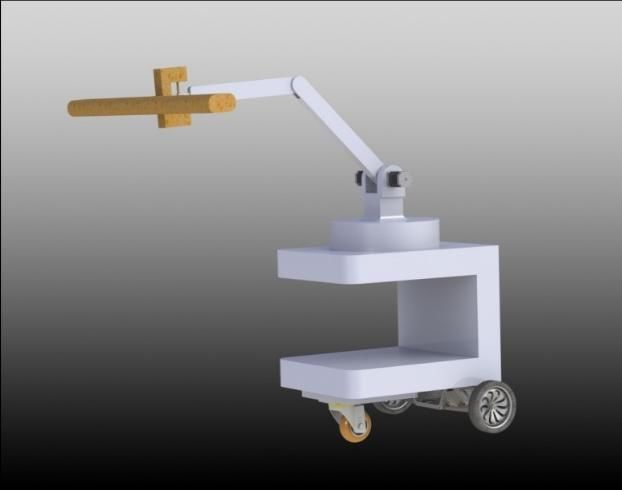
International Journal of Mechanical Engineering and Robotics Research Vol. 11, No. 3, March 2022

and PV’s tilting angles or comparing between the robot for a unit step response of robot arm speed. Finally, in
velocity with PV efficiency [11]. They are also interested section 7, the conclusions of this work are presented.
in the effect of different robot end effectors with PV power
[12]. The first ever robotized system for cleaning II. ROBOT MECHANICAL DESIGN
photovoltaic panel arrays at a large-scale solar park is
 With rising cost of electricity and concern for the
presented. The PV Cleaner Robot consists of two
 environmental impact of fossil fuels, implementation of
motorized trolleys plus a cleaning head motivated by a belt
 eco-friendly energy sources which are similar solar power
and pulley system. The cleaning head is designed to clean
while moving upwards and downward. It is made up of two is growing. One of the main problems of photovoltaic (PV)
sets of sprayers to put the cleaning solution, two rotating efficiency is soil and dust particles which are accumulated
 reducing the solar energy, thereby, falling overall power
cylindrical brushes to scrub the photovoltaic panels, a
 performance.
scraper to remove the dirty solution, and directs it away
from the panels that have been cleaned [13]. Our Since this robot is designed to clean the panels in solar
participation takes into consideration controlling the speed cell farms and PV arrays, the robot wheels are strictly
of the robot arm to prevent PV panels from being damaged selected to suit rough surface location. The robot consists
in different areas regardless of the efficiency of these of the base, two arms and one wiper. The first arm is
panels. welded to the base as well as it is connected to the second
 In this paper, we present a novel self-guided mobile arm by joints. One of the main objectives of motion
robot for cleaning PVP panels in real-time without modeling of mechanisms is the design of simplified or
requiring any special hardware In order to pursue the pilot model. Consequently, this model has been drawn
realization of self-guided autonomous mobile robot using solid work program. Solid modeling is currently the
platform, the fulfillment of several important targets have main method to create new structures of engineering
to be considered during this research such as high cleaning products and modernize the existing ones. The advantages
efficiency, reduction the costs, and minimizing the energy of solid modeling systems like SolidWorks are realistic
consumption. According to the state-of-the art, the main visual representation of the future product. Fig. 1
contributions of the paper can be briefly described as illustrates 3D model of the robot.
follows: (i) the new design is based on cleaning a large
group of cells without need a robot system for each cell.
Other researches rely on a slider or brush system that is
moved from cell to cell manually. In the proposed platform,
the system is moving automatically; (ii) the robot platform
does not require any attached guide rails to move on the
PVP. Therefore, the robot is fully autonomous on
unstructured environment; (iii) unlike other systems where
the rotation of the brush could create uncontrolled
dispersion of the removed sand on previous cleaned
regions, the proposed system combined with motion and
cleaning strategies has ability to regulate the sand
removing without any re-deposition; (iv) the real-time
motion control of the robot position is the design key for
the autonomous drive of the robot. As a consequence, due
to the regularity of the area to be cleaned and to the
proposed motion strategy, the robot does not require a path
recognition obtained by different techniques such as the
 Figure 1. Robot design
mobile robot navigation, Path Planning and Motion
Coordination and a set of wireless sensor networks or
 A. Material Selection and Mass Optimization
vision sensors; (vi) the proposed robot can be position
controlled based on any tilting angle panels and the Mass studies are important for many reasons; the main
position and velocity of the robot arm could be adjusted reason is the power consumption. In order to reduce the
according to the desired tilting angle values. mass, many alternatives were touched on like hollow links.
 The rest of this paper is organized in accordance with Aluminum material is selected for this design because it
the following sections: In section 2, a short overview of doesn’t need to empty the links to maintain the strength
new robot design with specific dimensions have been and deflection resistance.
selected. Section 3 describes the derivation of
 B. Dimensions Selection
mathematical equations of this design. The selected PV
panel that the design was made based on is presented in The chosen dimensions are based on the space between
section 4. In section 5, the simulation results are validated cells. So as to move and clean easily. In order to take
using MATLAB Simulink such as robot position, velocity advantages of the U space of the base which facilitates
and applied force. Section 6 includes the evaluation results installing battery, motors, and other components.

© 2022 Int. J. Mech. Eng. Rob. Res 152

International Journal of Mechanical Engineering and Robotics Research Vol. 11, No. 3, March 2022

 Table I displays Aluminum properties such as density, driving rear wheels. In addition, the robot has front free
shear and modulus of elasticity. Also, it clarifies the wheel. The equations of motion below explain the robot
robot’s mass, volume area and surfaces area. These values movement. All values are carefully selected. Equation 1
generated by solid work program according to the shows the base movement in one direction. The total robot
dimensions which are selected for this design. mass effects are on robot displacement. Not only the
 motors and mass affect movement, but also friction force
 TABLE I. ALUMINIUM PROPERTIES AND ROBOT DIMENSIONS is taken in consideration. The robot walks on soil and
 Parameter Value Unit gravel road. This road is not smooth all the time. Therefore,
 the friction will impede robot movement.
 Density 2700 kg/m3
 ( + + ) ̈ + ̇ + = (1)
 Shear Modulus 25 GPa

 Modulus of Elasticity E 69 GPa

 Robot mass 115.83601 kg

 Arm mass 1.75419 kg

 Robot volume 42.90223 m3

 Arm volume 0.64970 m3

 Robot surface area 190.2057 m2

 Arm surface area 7.6453 m2
 Figure 2. Base robot free body diagram.

C. Robot Mechanical Parts Fig. 2 shows the R1 normal force of the robot is
 equivalent to robot’s weight. The second equation
 The base is modeled in a U shape to sustain some
 describes link and cleaner movement. These two parts
mechanical and electrical parts and cleaning components.
It is attached to the wheels at the bottom. Two of the moves together with angular velocity ̇ and angular
wheels are driven by motors, whereas, the front wheel is acceleration ̈ . The motor torque of stepper motor gives
manual. The base thickness is selected to be robust to avert this arm moment to rotate. In addition, the friction force
bending due to weight. The rotary plate is connected to the between the joints appears in Fig 3. The moment about
base at the top. It connects to the first link through pin center of mass of this link is illustrated in (2) assumes that
connection. It is shaped with fillets to reduce the stress the counter clockwise direction is positive.
concentration points. The two links are designed to allow
up and down motion. Also, they are permitted to reach an (2)
 ̈ + − + − =
angled position of the PV cell which make a perfect
contact while cleaning.
 The wiper is the end effector of robot’s arm. Its
dimensions were chosen based on the size of the solar cell
which was selected for this research. It was designed with
a low thickness which decreases the affecting load on the
cell as well as increases the cleaning process. There are
diverse shapes of cleaners used for this purpose. Some of
those are serrated, brush, and other patterns. In this paper,
the cleaner is chosen for it is softer on the cell, does not
cause scratches, and easier to move compared to other
designs.

 III. MATHEMATICAL MODEL OF THE SYSTEM
 The robot has two degrees of freedom. The movement
is defined by two independent variables. These variables
are x and θ. Therefore, the system has two governing
 Figure 3. The first link free body diagram.
equations to describe its motion.
 Total mass of the robot moves together in x-axis. The
 The cleaner free body diagram shown in Fig. 4 is tilting
total mass of robot, including of base, links, wiper and
motors. The source of input force which acts stim on this with an angle and having a mass 2 . The moment
mass from motors. The robot has two servomotors for two equation at center of mass shown below.

© 2022 Int. J. Mech. Eng. Rob. Res 153

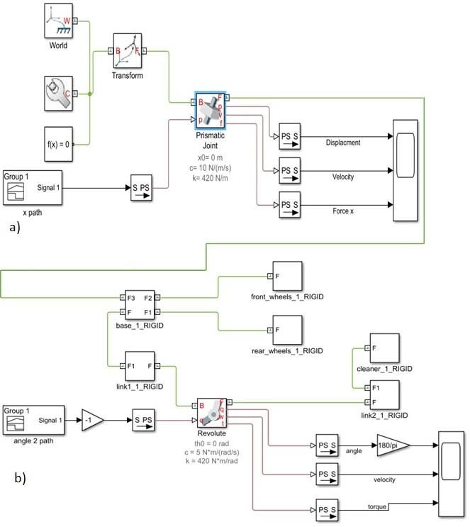
International Journal of Mechanical Engineering and Robotics Research Vol. 11, No. 3, March 2022

 ̈ + + = (3) IV. SIMULATION AND RESULTS

 The design of the presented system is formulated by
 using solid work and simulated as well as MATLAB
 program. The system is able to move along x axis for a
 specific time and stop to move the cleaner link along the
 PV panel with a controlled velocity in order to protect the
 PV panel from breakage, as well as the angle is controlled
 to move along PV panel. The motors torque is applied to
 move a robot cart.
 Fig. 6 reveals the block model that is simulated in
 MATLAB. X path signal is the cart path during the first 5
 seconds. This signal turns into physical signal which is an
 input to a prismatic joint. Angle signal is the cleaner path
 during the last 5 seconds of motion. Also, it turns into
 physical signal and enters to revolute joint. The results are
 displayed in two scopes as in Fig. 7 and 8. The cart motion
 (displacement and velocity) is shown in Fig. 7. The cleaner
 Figure 4. The cleaner free body diagram. analysis (position and velocity) is shown in Fig. 8. The 30⸰
 As shown in (1), friction force between the wheels and angle has been selected as a desired angle .
road depends on the kinetic friction coefficient and the The Simulink block is generated by the solid work.
normal force of robot. The motor torque is calculated by Signal 1 is the input signal for robot cart to move
using (4). The motor torque depends on robot weight and horizontally during the first 5 seconds and then stop. The
the wheel’s radius for the total robot mass. Also, the torque prismatic joint (linear motion joint) is made up of a moving
required to rotate the robot arm is computed using the same surface that slides linearly along a fixed a surface. The
principle, but the arm weight only is considered here. main criterion for evaluating prismatic joints is the
 stiffness-to-weight ratio. Achieving a good stiffness-to-
 = ̇ + (4) weight ratio requires the use of hollow structure for the
 moving elements rather than the solid rods. Signal 2 is the
 T is the motor torque. J is the motor inertia. C is the input signal to the rotational robot arm to move along the
motor damping coefficient. is the motor angular speed PV panel surface with 30⸰ degrees in the last 5 seconds of
that’s equal to the derivative of motor angle. motion. The revolute joint (rotary motion) is used to allow
 The robot is designed to work in large solar cell farms. pure rotation while minimizing radial and axial motions.
The design is selected to fit a specific solar cell. Ultra- The movement of robot from initial position to final one is
efficient polycrystalline is used in fabricating the solar displayed in Fig 9. Front, top, right and isometeric views
panel. Fig. 5 shows the solar panel specifications and its of this design are presented in Fig 10.
dimensions. Dimensions are in mm.

 Figure 5. Solar panel dimensions

 The position of the designed robot can be controlled
depending on any tilting angle panels. Employing the
Simulink, we can adjust the position and velocity of the
robot arm according to the desired values. This is one of
the features of this design. In this research, the selected
panel in Fig. 5 is presented as a case with 30⸰ tilting angle. Figure 6. Block diagram of the designed robot. (a) Cart horizontal path
 (b) robot arm movement with 30o angle

© 2022 Int. J. Mech. Eng. Rob. Res 154
International Journal of Mechanical Engineering and Robotics Research Vol. 11, No. 3, March 2022

 Some of blocks in Fig 6 are generated automatically
when the simulated calling the Solid work. Then these
blocks were connected together by adding some blocks to
convert the physical signal into unitless Simulink output
signal. Also, a prismatic joint between two frames is used.
This joint has one translational degree of freedom
represented by one prismatic primitive. The joint
constrains the follower origin to translate along the base z-
axis, while the base and follower axes remain aligned. A
revolute joint acting between two frames. This joint has
one rotational degree of freedom represented by one
revolute primitive. The joint constrains the origins of the Figure 9. Steps of robot movement
two frames to be coincident and the z-axes of the base and
follower frames to be coincident, while the follower x-axis
and y-axis can rotate around the z-axis.

 Figure 10. Views of robot design

 V. SYSTEM CONTROL
 The performance of a control system is identified in
Figure 7. The robot cart response, velocity and the motor force acting on terms of the transient response to a unit-step input. The
 it. dynamic behavior of the second-order system can then be
 descripted in terms of two parameters ζ and .
 The response of a system to a unit-step input depends
 on the system initial conditions. It is a public practice to
 use the standard at rest of the system initial condition is
 with the output and all-time derivatives thereof zero [14].
 A unit step input is employed to evaluate the arm
 response. The open loop transfer function of the robot arm
 is:
 1
 (5)
 1.754 2 +8.603 +20000

 The initial conditions are assumed to be zero. The unit
 step response of the robot arm is shown in Fig. 11. The
 system is underdamped second order response. The
 natural frequency and damping ratio are mentioned in table
 2. It can reduce the steady state error and system overshoot
 as well as decrease the settling time of the system by
 adding a PID controller to enhance the system
 performance.
 The performance of a feedback control system can be
 defined in terms of the location of the poles of system in
 Figure 8. The cleaner link position, angular velocity and the stepper the s-plane. A graph displaying how the poles of the
 motor torque
 characteristic equation moves around the s-plane as a
 single parameter diverges is known as a root locus plot.
 The root locus is a useful tool for designing and analyzing
 feedback control systems. In this paper, MATLAB tool is
 used for obtaining a sketch of a root locus plot for robot

© 2022 Int. J. Mech. Eng. Rob. Res 155
International Journal of Mechanical Engineering and Robotics Research Vol. 11, No. 3, March 2022

arm as it is represented in Fig. 12 [11]. This figure shows
all system poles on the left-hand side of s-plane, so the
system is stable. The root locus figure representing the
asymptotes are vertical and parallel to the imaginary axis,
however, the system is stable for all values of controller
gain. The root locus doesn’t cross the imaginary axis.
 This system has a type zero control system. Therefore,
 1
there is a steady state error equal to where Kp is the
 1+
position error constant.

 Figure 12. Root locus of robot arm unit step response

 In order to enhance the response of the robot arm, more
 than one optimization method is used in addition to making
 use of different types of controllers as Fig. 13 and Fig. 14
 show. Then, compare each method results to select the best
 one for our design.

 Figure 11. Step response of robot arm

 Figure 13. Flow chart of different optimization methods.

 TABLE II. PERFORMNACE OF ARM STEP RESPONSE USING PID CONTROLLER.
 Settling Over-shoot Damping Natural Peak time Max. peak Time
 time ratio frequency constant
 1.5898 sec 93.0372% 0.0231 1.07rad/s 0.0294 sec 9.6514e-05 4.08e-01

 3.5735 sec - >1 1.07rad/s 9.6338 1.0000 -

 VI. CONCLUSION
 This paper has presented the design, modeling and
 simulation with two DOF PV cleaning robot. It is capable
 of overcoming some major problems faced by the earlier
 developed cleaning robots. The main advantage of the
 proposed robot is that it can be used to clean the solar cells
 in a wide area as well as it is capable of moving in both the
 translational and rotational motion. In addition, it is
 controlled to accommodate different variables such as tilt
 angle, robot position and speed. The range of the tilting
 angle is limited to 0°and 30°. The cart velocity is between
 0 m/s and 0.2 m/s, and the arm angular velocity is between
 – 0.4 rad/s (cw) and 0.4 rad/s (ccw) which the arm moves
 up and down along PV panel. One of the disadvantages
 here is the size of the robot which is considered rather large,
 but this problem will be overcome by optimization and
 further analysis in the future.
 Figure 14. Robust response time after adding PID controller On the other hand, this design reduces the number of
 labors. So, the time and cost fall compared with other

© 2022 Int. J. Mech. Eng. Rob. Res 156
International Journal of Mechanical Engineering and Robotics Research Vol. 11, No. 3, March 2022

designs. These features are not the only advantages, but Engineering, Applied Sciences and Technology (ICEAST). IEEE,
 2019.
also a camera or sensor on the robot arm can be added. This
 [9] Chailoet, K., and E. Pengwang. "Assembly of Modular Robot for
component works as a sensor to measure the amount of Cleaning Various Length of Solar Panels." IOP Conference Series:
dust in order to increase the velocity of the arm to make Materials Science and Engineering. Vol. 639. No. 1. IOP
the solar cell cleaner as much as possible taking in to Publishing, 2019.
 [10] Narang, Reeka, and Varsha Sharma. "A Review on Solar Panel
account the force required for that to prevent solar cells
 Cleaning Robot using IoT." Thinking 6.11 (2019).
from damage. [11] Antonelli, Michele Gabrio, et al. "Autonomous robot for cleaning
 photovoltaic panels in desert zones." Mechatronics 68 (2020):
 CONFLICT OF INTEREST 102372.
 [12] Cai, Shibo, et al. "Parameters optimization of the dust absorbing
 The author declares that there are no conflicts of interest structure for photovoltaic panel cleaning robot based on orthogonal
regarding the publication of this article. experiment method." Journal of cleaner production 217 (2019):
 724-731.
 [13] Anderson, Mark, et al. "Robotic device for cleaning photovoltaic
 AUTHOR CONTRIBUTIONS panel arrays." Mobile Robotics: Solutions and Challenges. 2010.
 367-377.
 Ayat A. Al-Jarrah designed and directed the idea. Rami [14] Dorf, Richard C., and Robert H. Bishop. "Modern control systems."
A. and Fadwa W. designed the model. Ayat A. Al-Jarrah (1998).
and Rami A. carried out the simulation. Ayat A. Al-Jarrah,
 Copyright © 2022 by the authors. This is an open access article
Rami A. and Mohammad A. added the design and distributed under the Creative Commons Attribution License (CC BY-
implementation of the research, discussed the results and NC-ND 4.0), which permits use, distribution and reproduction in any
contributed to the final manuscript. Ayat A. Al-Jarrah and medium, provided that the article is properly cited, the use is non-
Manar H. took the lead of writing the manuscript. commercial and no modifications or adaptations are made.

 Ayat A. Al-Jarrah received the M.S. degree in
 NOMENCLATURE mechanical engineering from Jordan University of
 Science and Technology in 2011. She is working
 Friction coefficient between the robot wheels and as instructor in the Mechatronics Engineering
 the ground Department at The Hashemite University. Her
Fi Input force from motors research interests include control system,
l1 First link length modeling, and energy systems.
l2 Cleaner link length
M Base robot mass
m1 First link mass
m2 Cleaner mass Rami AL-Jarrah, He is Assistant Professor at
R Reaction Force or Normal Force Mechanical Engineering Department, Hashemite
r Wheel radius University, Jordan. He earned Dr.-Ing. of
x The base displacement Robotics and Control Systems from Regelungs-
 The angle of rotation for the cleaner link und-Steuerungstechnik Institute, Siegen
 University, Germany. His research interests
 The angle of rotation for the first link include Mechanical Design and Modeling, Fuzzy
AC Air Conditioning Control, Control Systems, Mobile Robots
PV Photovoltaic Navigations & Optimizations, and WSNs.

 Fadwa W. Al-Momani received the M.S. degree
 REFERENCES
 in mechanical engineering from Albalqa’
[1] NallapaeniManoj Kumar. “Dust cleaning robots (DCR) for BIPV University in 2011. She is working as instructor in
 and BAPV solar power plants-A conceptual framework and the Mechatronics Engineering Department at The
 research challenges.” Procedia Computer Science 133(2018): 746-
 Hashemite University. Her research interests
 754.
[2] Shinde, Sonone and Atalkar. “Automatic Solar Panel Cleaning include control system, modeling, and transduces
 System.” International Journal of Advance Research in Science and and sensors.
 Engineering. 2018: 2319-8354.
[3] Mobin, Shaikh Tariq. Design and development of solar panel
 cleaning system. Diss. 2015.
[4] Vishaal, Raj, et al. "Design of Dual Purpose Cleaning Robot." Mohammad Ababneh received his Ph.D. and
 Procedia computer science 133 (2018): 518-525. M.S. Degrees in Electrical engineering from
[5] Aureliano, Filipe Santos, AriellenAparecida Fidelis Costa, and University of Houston, USA in the years 2004 and
 Alexandre de Oliveira Lopes. "Cleaning and Inspection of Air 1993 respectively, and B.S. in Electrical
 Conditioning Ducts with Rover Explorer Robot." Procedia Engineering from Jordan University of Science
 Manufacturing 17 (2018): 350-356. and Technology in 1989. He is a full professor in
[6] AKYAZI, Ömür, et al. "A Solar Panel Cleaning Robot Design and the department of Mechatronics Engineering of
 Application." Avrupa Bilim ve Teknoloji Dergisi (2019): 343-348. the Hashemite University in Jordan. His research
[7] Jingshu, Wang, et al. "Sucker’s reliability analysis of photovoltaic interests include control systems, system
 panel cleaning robot." MS&E 383.1 (2018): 012056. synchronization, and energy systems.
[8] Ronnaronglit, Nawat, and Noppadol Maneerat. "A Cleaning Robot
 for Solar Panels." 2019 5th International Conference on

© 2022 Int. J. Mech. Eng. Rob. Res 157
International Journal of Mechanical Engineering and Robotics Research Vol. 11, No. 3, March 2022

 Manar B.AL Hajji received the M.Sc. degree in
 Industrial engineering from Jordan of Science and
 technology in 2013. She is working as a Full-time
 – lecturer in the Mechanical Engineering
 Department at The University of Jordan. Her
 research interests include Materials Science,
 Renewable Energy and water resources, Product
 design and Development.

© 2022 Int. J. Mech. Eng. Rob. Res 158
You can also read